HPLC A Practical User’s Guide P2 potx
Bạn đang xem bản rút gọn của tài liệu. Xem và tải ngay bản đầy đủ của tài liệu tại đây (219.58 KB, 20 trang )
I recommend a dynamically stirred, two-pump, high-pressure mixing system.
If, on the other hand, you’ll mainly be doing scouting gradients, dial-a-mix iso-
cratics, and the occasional uncomplicated gradient, the low-pressure mixing
system would be excellent and save you about $4,000. This system has the
advantage of giving you three- or four-solvent capability, which would be of
advantage in scouting and automated wash-out, but it requires continuous,
inert gas solvent degassing. I generally find low-pressure mixing gradient
reproducibility performance to be about 95% that of the high-pressure mixing
system. Gradients from 0 to 5% and 95 to 100% B may be worse than 95%
and should be checked before buying (see Chapter 9).
You can replace an integrator-based data acquisition system with a com-
puter-based system, but let the buyer beware. I am not impressed with most
of the control/data acquisition add-on systems I’ve seen. The system made by
Axxion runs on most systems, is competitively priced, and is reasonably
friendly. For maximum control and processing benefit, the computer and soft-
ware have to be carefully matched to the HPLC hardware. If I was going to
buy anything, I’d get data acquisition/processing only. My operating rule is to
“try it before you buy it” and think again. I’ve been using personal computers
for 25 years; I’m a fan,but I’m still not convinced that most people can upgrade
to a useful component system. Manufacturers carefully match computer and
HPLC hardware with optimized software and, even then, many control/pro-
cessing systems leave much to be desired. If you do buy a computer to acquire
data, keep your integrator or strip chart recorder. You will thank me.
2.2.3 Type III System—Automated Clinical (Cost: $25–35,000)
The most common job for these systems is the fast-running isocratic separa-
tion. They could be built up from the QC isocratic, but dial-a-mix isocratic is
faster and more convenient since they switch easily from job to job. These
systems come in the same two flavors as the research gradient, low- and
high-pressure mixing, but replace the manual injector with an autosampler,
allowing 24-hr operation. For thermally labile samples that need to be held
for a period of time before being injected, there are autosampler chillers
available.
The components in these systems tie together, start with a single start
command, and may be capable of checking on other components to make sure
of their status.The controllers usually will allow different method selection for
different injection samples. The more expensive autosamplers allow variable
injection volumes and bar code vial identification for each vial. Since these
laboratories must retain chromatograms and reports for regulatory compli-
ance and good laboratory practice, they are moving more toward computer
control/data acquisition. At the moment, this will add an additional $5,000 to
the cost above for software and hardware. This assumes that the computer
system replaces the controller and integrator at purchase.
20 SELECTING AN HPLC SYSTEM
2.2.4 Type IV System—Automated Methods (Cost: $30–50,000)
Another fully automated gradient system, this system is most commonly found
in industrial methods development laboratories. They usually have an
autosampler, a multi-solvent gradient, at least a dual-channel, variable UV
detector and computer-based control, and data processing system for reports.
They may add a fraction collector to be used in standards preparation.
Some laboratories will replace the variable detector with a diode array detec-
tor/computer combination that can run the cost of this system to $60,000. Of
course, you could have two Type II systems for the same price. Other detec-
tors, such as a caronal charged aerosol detector or a mass spectrometer and
interface module, will dramatically increase the system price. In 2004, I talked
to a laboratory director who had just purchased an automated gradient HPLC
system with a linear ion trap mass spectrometer that cost $220,000! It depends
on what you are trying to achieve and how heavily budgeted your department
is at the moment.
2.3 COLUMNS
The decision about which HPLC column to choose is really controlled by the
separation you are trying to make and how much material you are trying to
separate and/or recover. I did a rather informal survey of the literature and
my customers 15 years ago to see which columns they used. I found 80% of
all separations were done on some type of reverse-phase column (80% of
those were done on C
18
), 10% were size separation runs (most of these on
polymers and proteins), 8% were ion-exchange separations, and 2% were
normal-phase separation on silica and other unmodified media, such as zirco-
nium and alumina. The percentage of size- and ion-exchange separations has
increased recently because of the importance of protein purification in pro-
teomics laboratories and the growing use in industry of ion exchange on pres-
sure-resistant polymeric and zirconium supports.
2.3.1 Sizes: Analytical and Preparative
Columns vary in physical size depending on the job to be accomplished and
the packing material used. There are four basic column sizes: microbore
(1–2mm i.d.), analytical (4–4.5mm i.d.), semipreparative (10–25mm i.d.), and
preparative (1–5 in i.d.). Column lengths will range from a 3-cm ultrahigh
resolution, 1–3-mm packed microbore column to a 160-cm semipreparative
column with 5mm packing. The typical analytical column is a 4.2-mm i.d.
× 25-cm C
18
column packed with 5mm media.
Size separation columns need to be long and thin to provide a sufficiently
long separating path. Preparative ion exchange and affinity columns should be
short and broad to provide a large separating surface.
COLUMNS 21
2.3.2 Separating Modes: Selecting Only What You Need
Column decisions should be made in a specific order based on what you are
trying to achieve. First,decide whether you are trying to recover purified mate-
rial or simply analyzing for compounds and amounts of each present (see
Fig. 5.4).
If you are going to make a preparative run, how much material will you
inject? Deciding this allows you to decide on an analytical (microgram
amounts) column, a semipreparative (milligram) column, or a preparative
(grams) column depending on the amounts to be separated (see Table 11.1).
Once the column size is decided, the next column decision is based on the
types of differences that will be needed to separate the molecules. The sepa-
rating factors might be size, the charge on the molecules, their polarities, or a
specific affinity for a functional group on the column.
For size differences, select a size-exclusion or gel-permeation column. A
further decision needs to be made based on the solubilities of the compounds.
Size separation columns are supposed to make a pure mechanical separation
dependent only on the diameters of the molecules in the mixture. Compounds
come off the column in order of size, large molecules first. Solvent serves only
to dissolve the molecules to they can enter the column pores and be separated
based on their resident times. Size columns come packed with either silica-
based, polymer-based, or gel-based packing in solvents specific for samples dis-
solved in either aqueous or organic solvents. Do not switch solvents or solvent
types on gel-packed columns; differential swelling can change the separating
range of the column, cause column voiding, or even crush the packing.
For charge differences, select either an anion-exchange or cation-exchange
column, either gel-based or bonded-phase silica or chelated zirconium.Anion-
exchange columns retain and separate anions or negatively charged ions.
Cation-exchange columns retain and separate positively charged cations.
Silica-based ion exchange columns are pressure resistant, but are limited to
pH 2.5–7.5 and degrade in the presence of high salt concentrations, which
limits cleaning charged contaminants off the column or separation of strongly
bound compounds. Zirconium-based ion exchange columns are resistant to
pressure, high temperature, and pH from 1-11, but they have Lewis acid func-
tionality that must be blocked to prevent non-ion exchange interacts that will
interfere with the separation. Column packing with bonded chelators has been
produced to overcome this problem.The functional group on either positively
or negatively charged columns can have permanent charges (strong ion
exchangers, either quaternary amine or sulfonic acid) or inducible charges
(weak ion exchangers, with carboxylic acid or secondary/tertiary amine). The
latter types can be cleaned by column charge neutralization through mobile-
phase pH modification. Ion exchangers do not retain or separate neutral
compounds or molecules with the same charge as the column packing.
For polarity differences, select a partition column. Look at solubilities in
aqueous and organic solvents again. Compounds soluble only in organic sol-
22 SELECTING AN HPLC SYSTEM
vents should be run on normal-phase (polar) columns. Compounds with struc-
tural or stereo isomeric differences should be separated on normal-phase
columns. Most compounds soluble in aqueous organic solvents should be run
on reverse-phase columns. Although C
18
columns are commonly used, inter-
mediate phase columns, such as the phenyl, C
8
, cyano, and diol columns, offer
specificity for double bonds and functional groups. Additives to the mobile
phase can modify polarity-based separations, such a strong solvent changes,
pH modification, and ion pairing agents.
This selection of separating modes is an oversimplification, but it serves as
a good first approximation and will be expanded on in later sections of this
book. There is rarely such a thing as a pure size column or column packing
that separates solely by partition. Many size columns control pore size by
adding bonded phases that can exhibit a partition effect. The underlying silica
support can have a cation-exchange effect on a partition separation.A bonded
phase column’s pore size can introduce size exclusion effects.Most separations
are a combination of partition, size, and ion-exchange effects, generally with
one separating mode dominating and others modifying the interactions. This
can be a problem when trying to introduce simple, clean changes in a separa-
tion, but it can be used to advantage if you are aware that it might be present.
2.3.3 Tips on Column Use
Here are a few tips on column usage that will make your life easier:
1. Keep the pH of bonded-phase silica column between 2.0 and 8.0 (better
is pH 2.5–7.5). Solvents with a pH below 2.0 remove bonded phases; all
silica columns dissolve rapidly above pH 8.0 unless protected with a sat-
uration column.
2. Always wash a column with at least six column volumes (approximately
20mL for a 4mm × 25cm analytical column) of a new solvent or a bridg-
ing solvent between two immiscible solvents.
3. Do not switch from organic solvents to buffer solution or vice versa.
Always do an intermediate wash with water. Buffer precipitation is a
major cause of system pressure problems. You may be able to go from
less than 25% buffer to organic and get away with it, but you are forming
a very bad habit and that will get you into trouble later on. I usually keep
a bottle of my mobile phase minus buffer on the shelf for column
washout at the end of the day. This also can be used for buffer washout,
but a water bridge is still the best.
4. Do not shock the column bed by rapid pressure changes, by changes to
immiscible solvents, by column reversing, or by dropping or striking the
column or the floor or the desktop.
5. Pressure increases are caused by compound accumulation, by column
plugging with insoluble materials, or by solvent viscosity changes. It is
COLUMNS 23
poor practice to run silica-based columns above 4,000psi (see Chapter
10 on troubleshooting for cleaning). Keep organic polymer columns and
large-pore silica size columns below 1,000psi or lower if indicated in the
instructions supplied with the column. Set your pump overpressure
setting, if it has one, to protect your column. Solvents mixtures such as
water/methanol, water/isopropanol,and DMSO/water undergo large vis-
cosity changes during gradient runs and washouts.Adjust your flow rates
and overpressure setting to accommodate these increases so the systems
does not shut down or overpressure columns.
6. Use deoxygenated solvents for running or storing amine or weak anion-
exchange columns (see “Packing Degradation,” in Chapter 6, for a
deoxygenating apparatus).
7. Wash out buffer, ion pairing reagents, and any mixture that forms solids
on evaporation before shutting down or storing columns. Store capped
columns in at least 25% organic solvent (preferably 100% MeOH or ace-
tonitrile) to prevent bacterial growth.
24 SELECTING AN HPLC SYSTEM
3
RUNNING YOUR
CHROMATOGRAPH
25
This chapter is designed to help you get your HPLC up and running. We will
walk through making tubing fittings, putting the hardware together, preparing
solvents and samples, initialization of the column, making an injection, and
getting information from the chromatogram produced. Let us begin with the
hardware and work our way toward acquiring information.
3.1 SET-UP AND START-UP
When your chromatograph arrives,someone will have to put it together. If you
bought it as a system, a service representative from the company may do this
for you. No matter who will put it together, you should immediately unpack
it and check for missing components and for shipping damage.
If you only bought components or if you are inheriting a system from
someone else, you will have to put it together yourself. More than likely, you
will need, at a minimum, the system manual, a 10-foot coil each of 0.010-in (10
thousandths) and 0.020-in (20 thousandths) tubing, compression fittings
appropriate to your system, cables to connect detectors to recorder/integra-
tors and pumps to the controller, and tools. Our model will be a simple, iso-
cratic system: a single pump, a flush valve, an injector, a C
18
analytical column,
a fixed-wavelength UV detector, and a recorder (see Fig. 1.4). The first thing
we need to do is to get the system plumbed up or connected with small inter-
nal diameter tubing. For now, check the columns to make sure they were
shipped or were left with the ends capped. We will put them aside until later.
HPLC: A Practical User’s Guide, Second Edition, by Marvin C. McMaster
Copyright © 2007 by John Wiley & Sons, Inc.
3.1.1 Hardware Plumbing 101: Tubing and Fittings
We will need 1/8-in stainless steel HPLC tubing with 0.020-in i.d. going from
the outlet check valve of the pump to the flush valve and on to the injector
inlet. Three types of tubing are used in making HPLC fittings, 0.04-in, 0.02-in,
and 0.01-in i.d.; the latter two types are easily confused. If you look at the ends
of all three types, 0.04-in looks like a sewer pipe, more hole than tube. Look
at the tubing end on; if you can see a very small hole and think that it is 0.01-
in it probably is 0.02-in. If you look at the end of the tubing and at first think
its a solid rod and then look again and can just barely see the hole, that’s 0.01-
in. From the injector to the column and from the column on to the detector
we will use 4-in pieces of this 0.010-in tubing.
It is critically important to understand this last point. There are two tubing
volumes that can dramatically affect the appearance of your separation; the
one coming from the injector to the column and from the column to the detec-
tor flow cell. It is important to keep this volume as small as possible. The
smaller the column diameter and the smaller the packing material diameter,
the more effect these tubing volumes will have on the separation’s appearance
(peak sharpness).
A case in point is a trouble-shooting experience that I had. We were visit-
ing a customer who had just replaced a column in the system. The brand new
column was giving short, broad, overlapping peaks. It looked much worse than
the discarded column, but retention times looked approximately correct. Since
the customer was replacing a competitive column with one that we sold, I was
very concerned. I asked her if she had connected it to the old tubing coming
from the injector and she replied that the old one did not fit. She had used a
piece of tubing out of the drawer that already had a fitting on it that would
fit. This is always dangerous since fittings need to be prepared where they will
be used or they may not fit properly. They can open dead volumes that serve
as mixing spaces. I had her remove the column and looked at the tubing. Not
only was tubing protruding from the fitting very short, the tubing was 0.04-in
i.d. This is like trying to do separations in a sewer pipe. We replaced it with
0.01-in tubing, made new fittings, and reconnected the column. The next run
gave needle-sharp, baseline-resolved peaks!
To make fittings, you need to be able to cleanly cut stainless steel tubing.
Do not cut tubing with wire cutters; that is an act of vandalism. Tubing is cut
like glass. It is scored around its circumference with a file or a micro-tubing
cutter. The best apparatus for this is called a Terry Tool and is available from
many chromatography suppliers. If adjusted for the internal diameter of the
tubing, it almost always gives cuts without burrs. If you do not have such a
tool, score around the diameter with a file. Grasp the tube on both sides of the
score with blunt-nosed pliers and gently flexed the piece to be discarded until
the tubing separates. Scoring usually causes the tubing to flare at the cut. A
flat file is used to smooth around the circumference. Then, the face of the cut
is filed at alternating 90° angles until the hole appears as a dot directly in the
26 RUNNING YOUR CHROMATOGRAPH
center of a perfect circle. The ferrule should then slide easily onto the tubing.
Make sure not to leave filings in the hole. Connect the other end to the
pumping system and use solvent pressure from the pump to wash them out.
The tubing is connected to the pump’s outlet check valve by a compression
fitting.The fitting is made up of two parts:a screw with a hex head and a conical
shaped ferrule (Fig. 3.1a). The top of the outlet valve housing has been drilled
and threaded to accept the fitting.
First, the compression screw then the ferrule are pushed on to the tubing;
the narrow end of the ferrule and the threads of the screw point toward the
tubing’s end.The end of the tubing is pushed snugly into the threaded hole on
the check valve. The ferrule is slid down the tube into the hole, followed by
the compression screw. Using your fingers, tighten the screw as snug as possi-
ble; then use a wrench to tighten it another quarter turn. As the screw goes
forward, it forces the ferrule against the sides of the hole and squeezes it down
onto the tubing, forming a permanent male compression fitting.The fitting can
be removed from the hole, but the ferrule will stay on the tubing. The tubing
must be cut to remove the ferrule.
It’s important not to overtighten the fitting. It should be just tight enough
to prevent leakage under pressure. Try it out. If it leaks, tighten it enough to
stop the leak. By leaving compliance in the fitting, you will considerably
increase its working lifetime. Many people overtighten fittings. If you work at
it, it is even possible to shear the head off the fitting. But please, do not.
There is a second basic type of compression fitting (Fig. 3.1b), the female
fitting, which you will see on occasion. Some column ends have a protruding,
threaded connector and will require this type of fitting. This fitting is made
SET-UP AND START-UP 27
Figure 3.1 Compression fittings. (a) Male fitting; (b) female fitting; (c) zero dead volume union.
from a threaded cap with a hole in the center. It slides over the tubing with
its threads pointed toward the tubing end. A ferrule is added exactly as above
and the tubing and the ferrule are inserted into the end of a protruding tube
with external threads. Tightening the compression cap again squeezes the
ferrule into the tapered end of the tube and down onto the tubing forming a
permanent fitting.The third type of device for use with compression fittings is
the zero dead volume union (Fig. 3.1c). A union allows you to connect two
male connection fittings. If these fittings are made in the union,it allows tubing
to be connected with negligible loss of sample volume.
You will find that stainless steel fittings will cause you a number of
headaches over your working career. An easier solution in many cases is the
polymeric “finger-tight” fittings sold by many supplier such as Upchurch and
SSI. These fittings slide over the tubing and are tightened like stainless steel
fittings, but are not permanently “swagged”onto the tubing and can be reused.
They are designed to give a better zero-dead-volume fitting, but they have
pressure and solvent limits.They are also more expensive, but only in the short
run.
3.1.2 Connecting Components
New pumps are generally shipped with isopropanol or a similar solvent in the
pump head, and this will need to be washed out. Always try and determine
the history of a pump before starting it up. Systems that have not been run for
a while may have dried out. If buffer was left in the pump, it may have dried
and crystallized. In any event, running a dry pump can damage seals, plungers,
and check-valves.
First we will need to hook up the pump inlet line. This usually consists of a
length of large-diameter Teflon tubing with a combination sinker/filter pushed
into one end and a compression fitting that will screw into the inlet fitting at
the bottom of the pump head on the other end. Drop the sinker into the
solvent reservoir and screw the other end into the inlet check valve housing.
The next step is to use compression fittings to hook the pump outlet to the
flush valve with a length of 0.02-in i.d. tubing.The flush valve is a small needle
valve used to prime the pump that allows us to divert solvent away from the
column when rapidly flushing the pump to atmospheric pressure. Open the
valve and the line is vented to the atmosphere. This removes the back-pres-
sure from the column, a major obstacle when trying to push solvent into a
plumbed system.
From the flush valve we can connect with fittings and 0.02-in tubing onto
the injector inlet port. The back of the injector usually has ports for an inlet,
an outlet, two ports for the injection loop, and a couple of wash ports. If a
sample loop is not in place, connect it, then make a short piece of 0.01-in i.d.
tubing with fittings to be used in connecting the column. Use the column end
to prepare the compression fitting that will fit into it (Fig. 3.2). At the outlet
end of the column, hook up with compression fittings a piece of 0.01-in tubing
28 RUNNING YOUR CHROMATOGRAPH
that connects to the detector flow cell inlet line. When this is done, remove
and recap the column and set it aside.
Next, we are going to create a very useful tool for working with the HPLC
system. I call it a “column blank” or column bridge (Fig. 3.3). It bridges over
the place in the system where we would normally connect the column. It is
very valuable for running, problem diagnosis, and for cleaning a “column less
system.” It is made up of a 5-ft piece of 0.01-in tubing with a male compres-
sion fitting on each end screwed into a zero-dead-volume union
(female/female). Our column blank now has two ends simulating the end fit-
tings on the column.
SET-UP AND START-UP 29
Figure 3.2 Column inlet compression fitting.
Figure 3.3 Column blank.
Connect one end of your column blank to the tubing from the injector
outlet; the other end is connected to the line leading to the detector flow cell.
We have one more fluid line to connect to complete our fluidics. A piece of
0.02-in tubing can be fitted to the detector flow cell outlet port to carry waste
to a container. In some systems, this line will be replaced with small-diameter
Teflon tubing.
In either case, the line should end in a back-pressure regulator, an
adjustable flow resistance device designed to keep about 40–70psi back-pres-
sure on the flow cell to prevent bubble formation that will interfere with the
detector signal. Air present in the solvent is forced into solution during the
pressurization in the pump. The column acts as a depressurizer. By the time
our flow stream reaches the detector cell, the only pressure in the system is
provided by the outlet line. If this is too low, bubbles can form in the flow cell
and break loose, resulting in sharp spikes in the baseline. The back-pressure
regulator prevents this from happening.
The final connections are electrical. A power cable needs to be connected
to each pump. Check the manuals to see whether fuses need to be installed
and do so if required. Finally, connect the 0–10mV analog signal connectors
on the back of the detector to the strip chart recorder. Connect red to red,
black to black. If a third ground wire is present in the cable, connect it only at
one end, either the detector or the recorder end. (Note: The ground wire con-
nects to the cable shield, which is wrapped around the other two wires in the
cable. If no ground is connected, no shielding of the signal occurs. If both ends
of a ground are connected, the shield becomes an antenna; worse than no
shield at all.)
Now our system is ready to run. We will need to prepare solvent, flush out
each component, then connect, flush out, and equilibrate the column before
we are ready to make our first injection of standard.
3.1.3 Solvent Clean-up
Before we tackle the column, let us look at how to prepare solvents for our
system. I have found that 90% of all system problems turn out to be column
problems. Many of these can be traced to the solvents used, especially water.
Organic solvents for HPLC are generally very good. There are three rules
of thumb to remember: always use HPLC grade solvents, buy from a reliable
supplier,and filter your solvents and check them periodically with your HPLC.
Most manufacturers do both GLC and HPLC quality control on their solvents;
some do a better job than others.The best way to find good solvents is to talk
to other chromatographers.
Even the best solvents need to be filtered. I have received HPLC-grade ace-
tonitrile, from what I considered to be the best manufacturer of that time, that
left black residue on a 0.54-mm filter. There is a second reason to filter sol-
vents.Vacuum filtration through a 0.54-mm filter on a sintered glass support is
an excellent way to do a rough degassing of your solvents. Because of filter
30 RUNNING YOUR CHROMATOGRAPH
and check valve arrangements, some pumps cavitate and have problems
running solvents containing dissolved gases.
There are numerous filter types available for solvent filtration. The cellu-
lose acetate filters should be used with aqueous samples containing less than
10% organic solvents. With much more organic in the solvent, the filter will
begin to dissolve and contaminate your sample. Teflon filters are used for
organic solvent with less than 75% water. The two types are easily told apart;
the Teflon tends to wrinkle very easily, while the cellulose is more rigid. If you
are using the Teflon filter with high percentages of water in the solvent, wet
the filter first with the pure organic solvent, then with the aqueous solvent
before beginning filtration. If you fail to do this it will take hours to filter a
liter of 25% acetonitrile in water. Nylon filters for solvent filtration can be
used with either aqueous or organic solvents. They work very well as a uni-
versal filter, but use with very acidic or basic solutions should be avoided as
they break down the filter.
If you’re still having pumping problems after vacuum filtration, try placing
the filtrate in an ultrasonication bath for 15min (organic solvents) or 35min
(aqueous solvents). Ultrasonic baths large enough to accept a 1-L flask are in
common use in biochemistry labs and are very suitable for HPLC solvent
degassing. Stay away from the insertion probe type of sonicator; they throw
solvent and simply make a mess. Ultrasonication is much better than heating
for degassing mixed solvents. There is much less chance of fractional distilla-
tion with solvent compositional change when placing mixtures in an ultrasonic
bath. One manufacturer actually made a system that was designed to remove
dissolved gas by heating mobile phase under a partial vacuum. Obviously
they never used rotary vacuum flash evaporators in their labs, at least not
intentionally!
Other techniques recommended for solvent degassing involve bubbling
gases (nitrogen or helium) through the solvent. Helium sparging is partially
effective, but expensive when used continuously. It is required in some low-
pressure mixing gradient systems, as will be described later. The only other
time I use any of these techniques is in deoxygenating solvent for use with
amine or anionic exchange columns, which tend to oxidize (see Fig. 6.4).
Water is the major offender for column contamination problems. I have
diagnosed many problems, which customers have initially blamed on detector,
pumps, and injectors, that turned out to be due to water impurities. Complex
gradient separations are especially susceptible to water contamination effects.
In one case, the customer was running PTH amino acid separation, a
complex gradient run on a reverse-phase column. He would wash his column
with acetonitrile, then water, and run standards. Everything looked fine. Five
or six injections later his unknown results began to look weird. He ran his stan-
dards again only to find the last two compounds were gone. He blamed the
problem on the detector. I said it looked like bad water. He exploded, told me
that his water was triple distilled and good enough for enzyme reactions. It
was good enough for HPLC, he said. Over the following 6mo we replaced
SET-UP AND START-UP 31
every component in that system as each in turn was blamed for the chro-
matography problem. Eventually, the customer borrowed HPLC-grade water
from another institution, washed his column with acetonitrile, then with water.
The problem disappeared and never came back—until he went back to his
own water. Nonpolar impurities co-distilling with the water were accumulat-
ing at the head of the column and retaining the late runners in the column.
While HPLC grade water is commercially available, I have found it to be
expensive and to have limited shelf life. The best technique for purifying
water seems to be to pass it through a bed of either reverse-phase packing
material or of activated charcoal, as in a Milli-Q system. Even triple distilla-
tion tends to co-distill volatile impurities unless done using a fractionation
apparatus.
I have used an HPLC and an analytical C
18
column at 1.0mL/min overnight
to purify a liter of solvent for the next day’s demonstration run. The next
morning, I simply washed the column with acetonitrile, then with water, equi-
librated the column with mobile phase, and ran my separation. It might be
better to reserve a column strictly for water purification if you are going to
use this technique regularly.
An even better solution is to use vacuum filtration through a bed of reverse-
phase packing. Numerous small C
18
SFE cartridges are available that are used
for sample clean-up and for trace enrichment.They are a tremendous boon to
the chromatographer for sample preparation, but also can be of help in water
clean-up. These SFE cartridges are a dry pack of large pore size C
18
packing
and must be wetted before use with organic solvent, then with water or an
organic solution.You wash first with 2mL of methanol or acetonitrile and then
with 2mL of water before applying dissolved sample. If you forget and try to
pass water or aqueous solutions through them, you well get high resistance
and nonpolars will not stick. SFE cartridges contain from 0.5 to 1.0g of packing
and will hold approximately 25–50mg of nonpolar impurities. If care is taken
not to break their bed, they can be washed with acetonitrile and water for
reuse. Eventually, long eluting impurities will build up and the SFE must be
discarded. I have used them about six times, cleaning about a liter of single
distilled water on each pass. If larger quantities of water are required, com-
mercially available reverse phase, vacuum cartridge systems using large-pore,
reverse-phase packing designed to purify gallons of water at a time are
available.
The most common choice for large laboratories are mixed bed, activated
charcoal, and ion exchange systems that produce water on demand. These
systems usually have a couple of ion-exchange cartridges and one activated
charcoal filter in series.They work very well, but I prefer to have the charcoal
as the last filter in the purification bank. After all, we are trying to remove
organics. I find that the ion-exchange resins break down after about 6mo and
begin to appear in the water.The system uses an ion conductivity sensor as an
indicator of water purity, but water that passes this test still may be unsuitable
for HPLC use.
32 RUNNING YOUR CHROMATOGRAPH
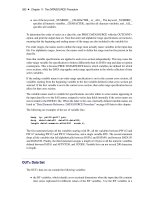
3.1.4 Water Purity Test
The final step is to check the purity of the solvents. Again, I have found the
C
18
column to be an excellent tool for this purpose. Select either 254nm or the
UV wavelength you will be using for the chromatogram.Wash the column with
acetonitrile until a flat UV baseline is established and then pump water though
the column at 1.0mL/min for 30min. This allows nonpolar impurities to accu-
mulate on the column. The final step is to switch back to acetonitrile. I prefer
to do this by running a gradient to 100% acetonitrile over 20min. If no peaks
appear after 5min at final conditions, the water is good. The chromatogram
(Fig. 3.4) gives you an idea of the expected baseline appearance.
Peaks that appear during the first acetonitrile washout are ignored as impu-
rities already on the column. Watch the baseline on switching to water.At 254
nm, the baseline should gradually elevate. If instead it drops, you may have
impurities in your acetonitrile. If the baseline makes a very sharp step up
before leveling off, you may have a large amount of polar impurities in the
water.Polar impurities probably will not bother you on reverse-phase columns
but might have some long-term accumulation effects. Peaks appearing during
the acetonitrile gradient come from nonpolar impurities in the water that accu-
mulated on the column and are now eluting.
I have done this with water from a Milli-Q system in need of regeneration.
Even though their indicator glow light shows no evidence of charged mater-
ial being released from the ion exchanger, peaks that will effect reverse-phase
chromatography show up at around the 70% acetonitrile portion of the gra-
dient run.
SET-UP AND START-UP 33
Figure 3.4 Water purity test.
If your water passes this test at the wavelength you will be using for your
chromatography, you are ready to use it to equilibrate the column. The next
step is to flush out the dry system and prepare to add the column.
3.1.5 Start-up System Flushing
Fill the solvent reservoir with degassed, filtered solvent by pouring it down the
wall of the flask to avoid remixing air into it. I usually start pumps up with
40–50% methanol in water. Even if the pump was shut down and allowed to
stand in buffer, there is a good chance this will clear it. It is also a good idea
to loosen the compression fitting holding the tubing in the outlet check valve
at the top of the pump head to relieve any system back-pressure. This is an
especially important step to use if the column is still connected.When running
with a column blank, as we are, it is less important.
The first step is to insure that the pump is primed. This may mean pushing
solvent from an inlet manifold valve through the inlet check valve and into
the pumping chamber.A few pumps on the market,like the old Waters M6000,
use spring-loaded check valves, so you may have to really work to get solvent
into the chamber. With other pumps, you open a flush valve and use a large
priming syringe to pull solvent through the pumphead. The next step is either
to turn the pump flow to maximum speed or uses the priming function of the
pump, which does the same thing.
As soon as the pump begins to pump solvent by itself, tighten down the
outlet compression fitting and drop the flow rate to about 1mL/min.The pump
is ready to run and should be allowed to pump into a beaker for a few minutes
to wash out any machining oils, if new, or soluble residues or dissolved buffer
if old.
Before we move on, let us talk about shutting down a pump.The pump seal
around the plunger is lubricated by the contents of the pumping chamber.
There is always a microevaporation through this seal/plunger combination,
whether the pump is running or not. Buffers and other mobile phases con-
taining dissolved solids should not be left in a pump when it is to be turned
off overnight. This evaporation causes crystallization on the sapphire plunger
and can result in either breakage or seal damage on starting up the pump. Sol-
vents containing dissolved solids should always be washed out before shut
down. I prefer to wash out and leave a pump in 25–50% methanol/water to
prevent bacteria growth in the fluidics system.
Occasionally, I have had to leave buffer in a pump overnight. In such a case,
I leave the pump running slowly (0.1mL/min.) and leave enough solvent in
the reservoir so that it can run all night. This has the additional value of
washing the column overnight. If the column is clean and doesn’t require
further washing, you can throw the detector outlet into your inlet reservoir
and recycle the solvent, ensuring you will not run out.
Now we can move past the flush valve to the next major system compo-
nent, the injector. Whichever position you find the injector handle in, leave it
34 RUNNING YOUR CHROMATOGRAPH
there! Never turn the handle on a dry injector. The injector seal is hardened
Teflon facing against a metal surface and can tear if not lubricated with solvent.
Once solvent is flowing through the injector to lubricate the seal, turn the
handle to the inject position so that the sample loop is washed.Watch the pres-
sure gauge on the pump; a plugged sample loop will cause the pressure to
jump. If this happens, go to the troubleshooting section in Appendix E.
3.1.6 Column Preparation and Equilibration
The next step is to hook up the column. Stop the pump flow. I assume you have
a C
18
column compatible with 40% methanol/water (otherwise, select a solvent
appropriate for your column). Disconnect the column bridge, remove the
column fittings from the ends of the stored column,and connect the inlet end of
the column to the line coming from the injector.The inlet end is almost always
marked;check for an arrow or a tag pointing the direction of flow.I have always
preferred to hook up a column with some solvent running.Turn the flow rate on
the pump down to 0.2mL/min. Fill the space in the end of the column fitting,
then screw in the compression fitting at the end of the injector line. Place a
beaker at the outlet end of the column to catch wash out solvent. Wash the
column with start-up solvent if it is an old column that might have been stored
in buffer. (Storing a column in buffer is a very bad technique, but you never
know if you weren’t the last person to use the column! It is a good idea to label
a column with the last solvent used in the column before you put it away.)
Next, change the solvent in the reservoir to 70% acetonitrile in water, turn
the pump on, and flush the column with the new solvent. Turn the flow rate
up to 1.0mL/min while catching the column effluent in a beaker. Check the
back-up line for leaks; if you see any, tighten the appropriate fittings until the
leaks just stop. You will always have leaks! If you do not, you are probably
overtightening your fittings. Leaks are messy, but are probably a sign of suc-
cessful technique (leaks, not streams).
Check the pump pressure. The pump pressure gauge and the baseline trace
are the two major tools for diagnosing system problems. If the column was
shipped in isopropanol or methanol it should start high (3,000–4,000psi) then
slowly drop to around 2,000–3,000psi.
Stop the flow and connect the column outlet with a short piece of 0.10-in
tubing to the inlet of the detector flow cell. Resume flow to the column. Turn
the detector on and start the recorder chart speed or computer data acquisi-
tion at 0.5cm/min. You should have a flat baseline. If the baseline continues
to drift up or down, the column still hasn’t finished its wash out and equili-
bration, or the detector has not fully warmed up.
By the way, I must hasten to add that we really haven’t reached a true equi-
libration at this point. The experts have informed me that it takes about 24hr
to reach a true equilibration on a reverse-phase packing. However, after six
column volumes we have reached a reproducible equilibration point good
enough for our purposes.
SET-UP AND START-UP 35
We are now ready to prepare for injecting a sample. Let’s turn our flow rate
down to 0.1mL/min and get our sample ready.
3.2 SAMPLE PREPARATION AND COLUMN CALIBRATION
The worst thing a chromatographer can do is to grab a column out of its box,
slap it into his HPLC, and shoot a sample. Before we begin, it’s important to
make sure the sample is clean. We will talk about removing soluble contami-
nants later. Here we’re going to be dealing with suspended solids or particu-
lates. Second, we need to know the initial condition of the column, so that we
may return to it when we begin to develop problems. In other words, we need
to need to do column quality assurance, or QA.
3.2.1 Sample Clean-up
The generally recommended procedure for cleaning samples is to filter them
through a 0.54-mm filter in a Sweeny filter holder or using a disposable plastic
filter cartridge. The same types of filter materials are available as those dis-
cussed in solvent filtration: Teflon, nylon and cellulose. In-line filters are avail-
able that fasten between the syringe barrel and the injection needle.These are
useful if you are not sample limited or are doing repeat injections of the same
material. I have found that most chromatographers won’t bother with the time,
cost, and sample loss that this entails, although I am finding an increase in the
use of syringe in-line filters.
Sample clarification is, however, important! The column frit pore size is
usually 2.0mm; any larger particulates build up and plug the frit. Being a lazy
chromatographer,but not a stupid one,I decided to use a different clarification
procedure. I place the sample in a microcentrifuge tube and sediment solids
by spinning at maximum speed in a clinical centrifuge (700 × g) for 1–2min. I
pull a sample carefully from the supernatant and shoot that as my sample. It
has the advantage of spinning down most of the solids, can be used on a
number of samples at the same time, works even with very small samples, and
is fast and inexpensive, if you already have the centrifuge.While it may not be
as efficient as filtration, most chromatographers are willing to use it on every
sample. It greatly extends column life between clean-ups.
A third alternative combines the two techniques.A commercially available
filter/reservoir fits in a microcentrifuge tube. Spinning the unit filters the
sample in the reservoir. It is more efficient than simple centrifugation, but
takes longer to assemble and costs more.
Like the oil filter advertisement says,“you can pay me now,or pay me later.”
If you don’t take time to remove particulates, you will spend much more time
and effort cleaning the column. The choice is yours.
36 RUNNING YOUR CHROMATOGRAPH
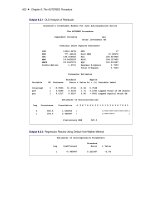
3.2.2 Plate Counts
Once the shipping solvent is washed out of the column, it is important to deter-
mine whether the column survived shipping and to determine its running con-
ditions. Most good chromatography laboratories have established a quality
control test for newly purchased columns. A stable test mixture of known
running characteristics has been prepared and stored to test new columns.
One commercially available standard used for testing C
18
columns is a solu-
tion of acetophenone, nitrobenzene, benzene, and toluene in methanol (many
chromatographers like to add a basic component, such as aniline, to the test
mixture as a check against tailing problems). To adjust for extinction coeffi-
cient differences, add 10mg of each of the first two ingredients and 30mg of the
last two compound in 2mL of MeOH. Inject 20 mL of the mixture into the
column equilibrated with 70% MeOH in water and read at 254nm on the UV
detector.This is a convenient mixture since a’s between pairs of peaks double
as you go to larger retention volumes. Be sure to keep this mixture tightly
stoppered.The last two compounds will evaporate from the mixture on access
to air. For use at low wavelengths, dissolve these same four ingredients in ace-
tonitrile and run in 60% acetonitrile in water.
Using this or similar mixtures, inject a sample into an equilibrated column,
elute the resolved bands, and record them on the recorder. Calculate plate
counts for the first and last peak using the “5s” method mentioned in Section
4.1.1. Log these numbers in the form V
4
/V
1
= 1.1/6.5; N
4
/N
1
= 7,500/3,600.When
we see changes in a separation we have been running, we can reequilibrate
the column in 70% MeOH/water and rerun our standards. Changes in these
ratios will be useful in troubleshooting column problems later on.
Obviously, this mixture will not be as useful on other types of columns,
although I have used this mixture on C
8
columns. Each column type should
have its own known standards mixture. They should be stable against both
chemical and bacterial changes. With them, you always have a touchstone to
return to in case of problems.
3.3 YOUR FIRST CHROMATOGRAM
Now that we have our system set up and the column equilibrated and
standardized, we are ready to carry out an HPLC separation on a real sample.
We might add an internal standard (if necessary, to correct for injection
variations), dilute our sample to a usable concentration, and prepare it for
injection. After injection, we will record the chromatogram making sure that
it stays on scale. Then, from the trace we obtain, we will calculate elution
volumes either by measuring peak heights or by calculating peak areas by
triangulation.
We can compare these values of areas or peak heights with known values
for standard compounds. From elution volumes or retention times, we can
YOUR FIRST CHROMATOGRAM 37
begin to identify compounds. Comparing peak areas or heights to those
derived from standard concentrations, we can calculate the amounts of mate-
rial under each peak.
3.3.1 Reproducible Injection Techniques
From the last section, it becomes obvious that we must first make a decision
about what we are trying to accomplish. We can do scouting, trying to identify
compounds by their retention times.Or,we can try to quantitate peaks by com-
parison to known amounts of standards.
In scouting, we may be running very expensive sample and have to simply
guess at the amount to inject. In this case, I would pull up >10mL of the super-
natant in a 25-mL syringe, turn the syringe point up, and pull the barrel back
far enough so I could see the meniscus just below the point where the needle
joins the barrel. (Injectors such as the Rheodyne injector use a blunt-tip
syringe needle. Sharpened needles cut and ruin the Teflon port liner.) I would
check for bubbles at the face end of the barrel, on the inside wall, and at the
meniscus. Small bubbles can generally be dislodged by gently snapping the
outside wall of the syringe with your finger. Slowly push the barrel forward to
the 10-mL mark, then quickly wipe the outside of the needle past the tip with
a tissue. Place the syringe needle into the injector syringe port, make sure the
injector handle is in the load position, and slowly push the sample into the
loop to insure that the sample goes in as a plug.
If the syringe is new or dry, you may find a large, tenacious bubble clinging
to the barrel face. It can be dislodged by rapidly expelling the sample from the
syringe back into the sample tube (try not to remix the pellet into the sample)
and then slowly pull up a new sample. Repeat the check for bubbles, expel the
excess sample, and wipe before injecting. Don’t let the tissue linger at the tip;
it can wick up extra sample and give irreproducible sampling.
When working with sample we don’t mind wasting, the simplest way to
achieve reproducible injections is to overfill the loop. With a 20-mL loop, we
need to flush with at least 30mL of sample to insure complete displacement of
mobile phase from the loop.
Quantitative sampling is handled a little differently. We usually know the
expected concentration level and retention times.After clarification, we add a
known amount of the sample solution and an internal standard to a volumet-
ric flask and dilute.The sample is pulled into the syringe for injection as above.
Internal standards are used for many reasons in chemistry. Here we are
using it to correct for differences in sampling volumes. It takes much practice
for a person to accurately deliver the same size sample every time. It is nearly
impossible for two people to accurately deliver the same sample each time if
they are partially injecting a loop. If we add a known amount of internal stan-
dard to both our sample and our known standard mixture, we can calculate
peak heights or areas relative to that of the internal standard. Variations in
the injection size of the sample do not affect these relative areas.
38 RUNNING YOUR CHROMATOGRAPH
To make the injection, we turn the handle of the injector to the load posi-
tion (see Fig.9.9). Push the syringe needle into the needle port and slowly push
the barrel forward so the sample goes in as a plug. Leave the needle in the
injector port to prevent siphoning of the sample out the waste port.The handle
is thrown quickly to the inject position.This last step is done quickly to prevent
pressure build up while the ports are blocked in shifting from one position to
the other. Remember: Load slowly, inject quickly.
Mark the injection point on the chromatogram. Some detectors, computer
systems, or integrators will do this for you automatically. It is good laboratory
practice to mark the injection with the operator’s initials, time, date, sample
number and injection volume, mobile phase composition, flow rate, detector
wavelength and attenuation, and chart speed. If a gradient is being run, mark
the starting composition, gradient start and end, and final composition. You
can annotate later injections only with conditions that change, such as sample
identification number and injection size. If you tend to cut your chro-
matograms apart, however, you may lose critical information if you fail to
annotate every run with full information. There are commercially available
rubber inkpad stamps that provide spaces for the necessary information. Do
not rely on your memory to come up with the data at some future time.
3.3.2 Simple Scouting for a Mobile Phase
My scouting gradient technique was developed when I had to make separa-
tions in a customer’s laboratory to sell an HPLC system.I only had a few hours
to make a separation to convince the customer that he should consider buying
a system. But, it provides useful insight for developing a method to use in your
laboratory.
The first step is to determine a starting point. If I am handed a mixture of
a completely unknown nature, I will probably first try to get more informa-
tion. I will try to determine the mixture’s solubility in organic solvents, the
effect of acid on the solubility, and something about the molecular weights and
isoelectric points if it is a mixture of proteins.
If this information is not available, I will try to separate the mixture using
a C
18
column in acetonitrile and water. Something like 70% of the separations
in the literature are now made on a C
18
silica-based column.Acetonitrile is my
solvent of choice because of its low wavelength transparency, its polarity, and
its intermediate position between methanol and tetrahydrofuran. Generally, I
will use 254nm for the detector because the majority of the literature separa-
tions can be made at this wavelength (see the Separations Guide in Appen-
dix A).
If I know that the compound is not soluble in aqueous solvents, I will prob-
ably select a silica column and a chloroform/hexane mobile phase. Separations
of proteins will take me first to a TSK-3000sw column and a 100mM Tris-
phosphate pH 7.2 mobile phase unless I am separating soluble enzymes; then
I use a TSK-2000sw column.
YOUR FIRST CHROMATOGRAM 39