High Level Synthesis: from Algorithm to Digital Circuit- P3 doc
Bạn đang xem bản rút gọn của tài liệu. Xem và tải ngay bản đầy đủ của tài liệu tại đây (465.81 KB, 10 trang )
6 P. U ra rd e t a l .
Low Power LDPC Encoder
(3 block size * 4 code rates = 12 modes)
240Mhz vs 120Mhz
Synthesis time: 5mn
T1
L1
T1
L2
T1
L3
time
T2
L1
Sequential
Specs not met
Task Overlapping
T1
L1
T1
L2
T1
L3
T2
L1
T2
L2
T2
L3
Specs met
( same as manual
implementation)
T1
L1
T1
L2
T1
L3
T2
L1
T2
L2
T1
L3
Task Overlapping
and double buffering
Specs met
(same throughput BUT
with half clock frequency)
T3
L1
T3
L2
T3
L3
240Mhz
0.15mm2
120Mhz
0.19mm2
Automatically
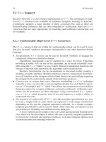
Fig. 1.7 HLS architecture explorations
Radix4
Radix2
-
-
+
-
-j
W
W
+
-
-
-
+
+
-j
W
2n
W
n
W
W
3n
X
0
X
1
X
2
X
3
S
0
S
1
S
2
S
3
X
0
-
+
-
+
W
P
-
+
-
+
X
1
X
2
X
3
W
q
-
+
-
+
-
+
-
+
W
s
W
r
X’
0
X’
1
X’
2
X’
3
S
0
S
1
S
2
S
3
4 multipliers
3 multipliers
Example: FFT butterfly radix2 radix4
Fig. 1.8 Medium term need: arithmetic optimizations
allow the designer to keep a high level of abstraction and to focus on functionality.
For sure this would have to be based on some pre-characterization of the HW.
Now HLS is being deployed, new needs are coming out for more automation and
more optimization. Deep arithmetic reordering is one of those needs. The current
generation of tools is effectively limited in terms of arithmetic reordering. As an
example: how to go from a radix2 FFT to a radix4 FFT without re-writing the algo-
rithm? Figure 1.8 shows one direction new tools need to explore. Taylor Expansion
Diagrams seems promising in this domain, but up to now, no industrial EDA tool
has shown up.
Finally after a few years spent in the C-level domain, it appears that some of the
most limiting factors to exploration as well as optimization are memory accesses. If
designer chose to represent memory elements by RAMs (instead of Dflip-flop), then
the memory access order needs to be explicit in the input C code, as soon as this is
not a trivial order. Moreover, in case of partial unroll of some FOR loops dealing
1 User Needs 7
with data stored in a memory, the access order has to be re-calculated and C-code
has to be rewritten to get a functional design. This can be resumed to a problem of
memory precedence optimization. The current generation of HLS tools have a very
low level of exploration of memory precedence, when they have some: some tool
simply ignore it, creating non-functional designs! In order to illustrate this problem,
let take an in-place FFT radix2 example. We can simplify this FFT to a bunch of
butterflies, a memory (RAM) having the same width than the whole butterflies, and
an interconnect. In a first trial, with a standard C-code, let flatten all butterflies (full
unroll): we have a working solution shown in Fig. 1.9.
Keep in mind that during third stage, we store the memory the C
0
= K.B
0
+ B
4
calculation. Let now try to not completely unroll butterflies but allocate half of them
(partial unroll). Memory will have the same number of memory elements, but twice
deeper, and twice narrower. Calculation stages are shown in Fig. 1.10.
We can see that the third stage has a problem: C
0
cannot be calculated in a sin-
gle clock cycle as B
0
and B
4
are stored at two different addresses of the memory.
With current tools generation, when B
0
is not buffered, then RTL is not-functional
X
0
X
1
X
2
X
3
X
4
X
5
X
6
X
7
A
0
A
1
A
2
A
3
A
4
A
5
A
6
A
7
B
0
B
1
B
2
B
3
B
4
B
5
B
6
B
7
C
0
C
1
C
2
C
3
C
4
C
5
C
6
C
7
C
0
= k.B
0
+ B
4
Example: 8 points FFT radix2
Fig. 1.9 Medium term need: memory access problem
X
4
X
5
X
6
X
7
A
0
A
1
A
2
A
3
A
4
A
5
A
6
A
7
B
0
B
1
B
2
B
3
B
4
B
5
B
6
B
7
Memory access conflict
X
0
X
1
X
2
X
3
?
Example: 8 points FFT radix2
C
0
= k.B
0
+ B
4
Implementation test case: in-place & 4 data in parallel
Fig. 1.10 Medium term need: memory access problem
8 P. U ra rd e t a l .
RTL to
layout
System
System
Analysis
Analysis
Algorithm
GDS2
GDS2
C/C++
Syst
e
mC
Code
C/C++
Sy
s
t
em
C
Code
Design
model
Target
Target
Asic
HLS
Technology files
(Standard Cells + RAM cuts)
RTL
TLM
Σ
Σ
Σ
Σ
C
RT
L
T
LM
Σ
Σ
Σ
C
Formal proof
(sequential
equivalence
checking)
DSE
Implementation
constraints
Formal proof
(sequential
equivalence
checking ?)
S
y
nth.
C/
Σ
Σ
Σ
Σ
C
code
S
yn
th.
C
Σ
ΣΣ
ΣC
co
d
e
/
Fig. 1.11 HLS flow: future enhancements at design space exploration level
because tools have weak check of memory precedence. HLS designers would
need a tool that re-calculate memory accesses given the unroll factors and inter-
face accesses. This would ease a lot the Design Space Exploration (DSE) work,
leading to find much optimized solutions. This could also be part of higher level
optimizations tools: DSE tools (Fig. 1.11).
Capacity of HLS tools is another parameter to be enhanced, even if tools have
done enormous progresses those last years. The well known Moore’s law exists and
even tools have to follow the semi-conductor industry integration capacity.
As a conclusion, let underline that HLS tools are working, are used in production
flows on advanced production chips. However, some needs still exist: enhancement
of capacity, enhancement of arithmetic optimizations, or automation of memory
allocation taking into account micro-architecture. We saw in the past many stand-
alone solutions for system-level flows, industry now needs academias and CAD
vendors to think in terms of C-level flows, not anymore stand-alone tools.
1.2 Samsung’s Viewpoints for High-Level Synthesis
Joonhwan Yi and Hyukmin Kwon, Telecommunication R&D, Samsung
Electronics Co.
High-level synthesis technology and its automation tools have been in the market for
many years. However the technology is not mature enough for industry to widely
accept it as an implementation solution. Here, our viewpoints regarding high-level
synthesis are presented.
The languages that a high-level synthesis tool takes as an input often character-
ize the capabilities of the tool. Most high-level synthesis languages are C-variant
including SystemC [1]. Some tools take C/C++ codes as inputs and some take
SystemC as inputs. These languages differ from each other in several aspects, see
1 User Needs 9
Table 1.1 The differences between C/C++ and SystemC as a high-level synthesis language
ANSI C/C++ SystemC
Synthesizable code Untimed C/C++ Untimed/timed SystemC
Abstraction level Very high High
Concurrency Proprietary support Standard support
Bit accuracy Proprietary support Standard support
Specific timing model Very hard Standard support
Complex interface design Impossible Standard support, but hard
Ease of use Easy Medium
Table 1.1. Based on our experience, C/C++ is good at describing hardware behavior
in a higher level than SystemC. On the other hand, SystemC is good at describing
hardware behavior in a bit-accurate and/or timing-specific fashion than C/C++.
High-level synthesis tools for C/C++ usually provide proprietary data types or
directives because C/C++ has no standard syntax for describing timing. Of course,
the degree of detail in describing timing by the proprietary mean is somewhat lim-
ited comparing to SystemC. So, there exists a trade-off between two languages. A
hardware block can be decomposed into block body and its interface. Block body
describes the behavior of the block and its interface defines the way of communi-
cation with the outer world of the block. A higher level description is preferred for
a block body while a bit-accurate and timing-specific detail description needs to be
possible for a block interface. Thus, a high-level synthesis tool needs to provide
ways to describe both block bodies and block interfaces properly.
Generally speaking, high-level synthesis tools need to support common syntaxes
and commands of C/C++/SystemC that are usually used to describe the hardware
behavior at the algorithm level. They include arrays, loops, dynamic memories,
pointers, C++ classes, C++ templates, and so on. Current high-level synthesis
tools can synthesize some of them but not all. Some of these commands or syntaxes
may not be directly synthesizable.
Although high-level synthesis intends to automatically convert an algorithm level
specification of a hardware behavior to a register-transfer level (RTL) description
that implements the behavior, it requires many code changes and additional inputs
from designers [2]. One of the most difficult problems for our high-level synthesis
engineers is that the code changes and additional information needed for desired
RTL designs are not clearly defined yet. Behaviorally identical two high-level codes
usually result in very different RTL designs with current high-level synthesis tools.
Recall that RTL designs also impose many coding rules for logic synthesis and lint
tools exist for checking those rules. Likewise, a set of well defined C/C++/SystemC
coding rules for high-level synthesis should exist. So far, this problem is handled by
a brute-force way and well-skilled engineers are needed for better quality of results.
One of the most notable limitations of the current high-level synthesis tools
is not to support multiple clock domain designs. It is very common in modern
hardware designs to have multiple clock domains. Currently, blocks with different
clock domains should be synthesized separately and then integrated manually. Our
10 P. U ra rd e t a l .
high-level synthesis engineers experienced significant difficulties in integrating syn-
thesized RTL blocks too. A block interface of an algorithm level description is
usually not detailed enough to synthesize it without additional information. Also,
integration of the synthesized block interface and the synthesized block body is done
manually. Interface synthesis [4] is an interesting and important area for high-level
synthesis.
Co-optimization of datapath and control logic is also a challenging problem.
Some tools optimize datapath and others do control logic well. But, to our knowl-
edge, no tool can optimize both datapath and control logic at the same time. Because
a high-level description of hardware often omits control signals such as valid, ready,
reset, test, and so on, it is not easy to automatically synthesize them. Some addi-
tional information may need to be provided. In addition, if possible, we want to
define the timing relations between datapath signals and control signals.
High-level synthesis should take into account target process technology for RTL
synthesis. The target library can be an application specific integrated circuit (ASIC)
or a field programmable logic array (FPGA) library. Depending on the target tech-
nology and target clock frequency, RTL design should be changed properly. The
understanding of the target technology is helpful to accurately estimate the area and
timing behavior of resultant RTL designs too. A quick and accurate estimation of
the results is also useful because users can quickly measure the effects of high-
level codes and other additional inputs including micro architectural and timing
information.
The verification of a generated RTL design against its input is another essential
capability of high-level synthesis technology. This can be accomplished either by a
sequential equivalence checking [3] or by a simulation-based method. If the sequen-
tial equivalence checking method can be used, the long verification time of RTL
designs can be alleviated too. This is because once an algorithm level design D
h
and
its generated RTL design D
RTL
are formally verified, fast algorithm level design ver-
ification will be sufficient to verify D
RTL
. Sequential equivalence checking requires
a complete timing specification or timing relation between D
h
and D
RTL
.Unless
D
RTL
is automatically generated from D
h
, it is impractical to manually elaborate the
complete timing relation for large designs.
Seamless integration to downstream design flow tools is also very important
because the synthesized RTL designs are usually hard to understand by human. First
of all, design for testability (DFT) of the generated RTL designs should be taken
into account in high-level synthesis. Otherwise, the generated RTL designs cannot
be tested and thus cannot be implemented. Secondly, automatic design constraint
generation is necessary for gate-level synthesis and timing analysis. A high-level
synthesis tool should learn all the timing behavior of the generated RTL designs such
as information of false paths and multi-cycle paths. On the other hand, designers
have no information about them.
We think high-level synthesis is one of the most important enabling technolo-
gies that fill the gap between the integration capacity of modern semiconductor
processes and the design productivity of human. Although high-level synthesis is
suffering from several problems mentioned above, we believe these problems will
1 User Needs 11
be overcome soon and high-level synthesis will prevail in commercial design flows
in a near future.
1.3 High Level Design Use and Needs in a Research Context
Alexandre Gouraud, France Telecom R&D
Implementing algorithms onto electronic circuits is a tedious task that involves
scheduling of the operations. Whereas algorithms can theoretically be described
by sequential operations, their implementations need better than sequential schedul-
ing to take advantage of parallelism and improve latency. It brings signaling into
the design to coordinate operations and manage concurrency problems. These prob-
lems have not been solved in processors that do not use parallelism at algorithm
level but only at instruction level. In these cases, parallelism is not fully exploited.
The frequency race driven by processor vendors shadowed the problem replacing
operators’ parallelism by faster sequential operators. However, parallelism remains
possible and it will obviously bring tremendous gains in algorithms latencies. HLS
design is a kind of answer to this hole, and opens a wide door to designers.
In research laboratories, innovative algorithms are generally more complex than
in market algorithms. Rough approximations of their complexity are often the first
way to rule out candidates to implementation even though intrinsic (and somehow
often hidden) complexity might be acceptable. The duration of the implementation
constrains the space of solutions to a small set of propositions, and is thus a bot-
tleneck to exploration. HLS design tools bring to researchers a means to test much
more algorithms by speeding up drastically the implementation phase. The feasi-
bility of algorithms is then easily proved, and algorithms are faster characterized in
term of area, latency, memory and speed.
Whereas implementation on circuits was originally the reserved domain of
specialists, HLS design tools break barriers and bring the discipline handy to non-
hardware engineers. In signal processing, for instance, it allows faster implementa-
tion of algorithms on FPGA to study their behavior in more realistic environment.
It also increases the exploration’s space by speeding up simulations.
Talking more specifically about the tools themselves, the whole stake is to deduce
the best operations’ scheduling from the algorithm description, and eventually from
the user’s constraints. A trade-off has to be found between user’s intervention and
automatic deduction of the scheduling in such a way that best solutions are not
excluded by the tool and complicated user intervention is not needed.
In particular, state machine and scheduling signals are typical elements that the
user should not have to worry about. The tool shall provide a way to show oper-
ations’ scheduling, and eventually a direct or indirect way to influence it. The
user shall neither have to worry about the way scheduling is implemented nor how
effective this implementation is. This shall be the tool’s job.
12 P. U ra rd e t a l .
Another interesting functionality is the bit-true compatibility with the original
model/description. This guarantee spares a significant part of the costly time spent
to test the synthesized design, especially when designs are big and split into smaller
pieces. Whereas each small piece of code needed its own test bench, using HLS
tools allows work on one bigger block. Only one test bench of the global entity is
implemented which simplifies the work.
Models are generally complex, and their writing is always a meticulous task. If
one can avoid their duplication with a different language, it is time saving. This
raises the question whether architectural and timing constraints should be included
inside the original model or not. There is no clear answer yet, and tools propose
various interfaces described in this book. From a user’s perspective, it is important
to keep the original un-timed model stable. The less it is modified, the better it is
manageable in the development flow. Aside from this, evolutions of the architecture
along the exploration process shall be logged using any file versioning system to
allow easy backward substitution and comparisons.
To conclude this introduction, it is important to point out that introduction of
HLS tools should move issues to other fields like dimensioning of variables where
tools are not yet available but the engineer’s brains.
References
1. T. Grotker et al., System design with SystemC, Kluwer, Norwell, MA, 2002
2. B. Bailey et al., ESL design and verification, Morgan Kaufmann, San Mateo, 2007
3. Calypto design systems, available at />4. A. Rajawat, M. Balakrishnan, A. Kumar, Interface synthesis: issues and approaches, Int. Conf.
on VLSI Design, pp. 92–97, 2000
Chapter 2
High-Level Synthesis: A Retrospective
Rajesh Gupta and Forrest Brewer
Abstract High-level Synthesis or HLS represented an ambitious attempt by the
community to provide capabilities for “algorithms to gates” for a period of almost
three decades. The technical challenge in realizing this goal drew researchers from
various areas ranging from parallel programming, digital signal processing, and
logic synthesis to expert systems. This article takes a journey through the years
of research in this domain with a narrative view of the lessons learnt and their impli-
cation for future research. As with any retrospective, it is written from a purely
personal perspective of our research efforts in the domain, though we have made a
reasonable attempt to document important technical developments in the history of
high-level synthesis.
Keywords: High-level synthesis, Scheduling, Resource allocation and binding,
Hardware modeling, Behavioral synthesis, Architectural synthesis
2.1 Introduction
Modern integrated circuits have come to be characterized by the scaling of Moore’s
law which essentially dictates a continued doubling in the capacity of cost-efficient
ICs every so many months (every 18 months in recent trends). Indeed, capacity
and cost are two major drivers of the microelectronics based systems on a chip
(or SOC). A pad limited die of 200 pins on a 130 nm process node is about 50
square millimeters in area and comes to about $5 or less in manufacturing and
packaging costs per part given typical yield on large volumes of 100,000 units or
more. That is area sufficient to implement a large number of typical SOC designs
without pushing the envelope on die size or testing or packaging costs. However,
the cost of design continues to rise. Figure 2.1 shows an estimate of design costs
which were estimated to be around US$15M, contained largely through continuing
P. Coussy and A. Morawiec (eds.) High-Level Synthesis.
c
Springer Science + Business Media B.V. 2008
13
14 R. Gupta and F. Brewer
SOC Design Cost Model
$342,417,579
$15,066,373
$10,000,000
$100,000,000
$1,000,000,000
$10,000,000,000
$100,000,000,000
1985 1990 1995 2000 2005 2010 2015 2020
Ye ar
TotalDesign Cost
(log scale)
RTL Methodology Only
With all Future Improvements
In-House P&
R
T
all Thin Enginee
r
Small Block Reus
e
IC Implementation tool
s
Large Block Reuse
IntelligentTestbench
ES Level Methodology
Fig. 2.1 Rising cost of IC design and effect of CAD tools in containing these costs (courtesy:
Andrew Kahng, UCSD and SRC)
advances in IC implementation tools. Even more importantly, silicon architectures –
that is, the architecture and organization of logic and processing resources on chip –
are of critical importance. This is because of a tremendous variation in the real-
ized efficiency of silicon as a computational fabric. A large number of studies
have shown that energy or area efficiency for a given function realized on a sili-
con substrate can vary by two to three orders of magnitude. For example, the power
efficiency of a microprocessor-based design is typically 100 million operations per
watt, where as reprogrammable arrays (such as Field Programmable Gate Arrays
or FPGAs) can be 10–20×, and a custom ASIC can give another 10× gain. In a
recent study, Kuon and Rose show that ASICs are 35× more area efficient that
FPGAs [1]. IC design is probably one of the few engineering endeavors that entail
such a tremendous variation in the quality of solutions in relation to the design
effort. If done right, there is a space of 10–100× gain in silicon efficiency when
realizing complex SOCs. However, realizing the intrinsic efficiency of silicon in
practice is an expensive proposition and tremendous design effort is expended to
reach state power, performance and area goals for typical SOC designs. Such efforts
invariably lead to functional, performance, and reliability issues when pushing lim-
its of design optimizations. Consequently, in parallel with the Moore’s law, each
generation of computer-aided design (CAD) researchers has sought to disrupt con-
ventional design methodologies with the advent of high-level design modeling and
tools to automate the design process. This pursuit to raise the abstraction level at
which designs are modeled, captured, and even implemented has been the goal of
several generations of CAD researchers. Unfortunately, thus far, every generation
has come away with mixed success leading to the rise of yet another generation that
seems to have got it right. Today, such efforts are often lumped under the umbrella
2 High-Level Synthesis: A Retrospective 15
term of ESL or Electronic System Level design which in turn means a range of
activities from algorithmic design and implementation to virtual system prototyping
to function-architecture co-design [43].
2.2 The Vision Behind High-Level Synthesis
Mario Barbacci noted in late 1974 that in theory one could “compile” the instruction
set processor specification (then in the ISPS language) into hardware, thus setting up
the notion of design synthesis from a high-level language specification. High-level
Synthesis in later years will thus come to be known as the process of automatic gen-
eration of hardware circuit from “behavioral descriptions” (and as a distinction from
“structural descriptions” such as synthesizable Verilog). The target hardware circuit
consists of a structural composition of data path, control and memory elements.
Accordingly, the process was also variously referred to as a transformation “from
behavior to structure.” By the early eighties, the fundamental tasks in HLS had been
decomposed into hardware modeling, scheduling, resource allocation and binding,
and control generation. Briefly, modeling concerned with capturing specifications
as program-like descriptions and making these available for downstream synthe-
sis tasks via a partially-ordered description that is designed to expose concurrency
available in the description. Task scheduling schedules operationsby assigning these
to specific clock cycles or by building a function (i.e., a scheduler) that determines
execution time of each operation at the runtime. Resource allocation and binding
determine the resources and their quantity needed to build the final hardware circuit.
Binding refers to specific binding of an operation to a resource (such as a functional
unit, a memory, or an access to a shared resource). Sometimes module selection has
been used to describe the problem of selecting an appropriate resource type from
a library of modules under a given metric such as area or performance. Finally,
control generation and optimization sought to synthesize a controller to generate
appropriate control signals according to a given schedule and binding of resources.
This decomposition of HLS tasks was for problem solving purposes; almost all of
these subtasks are interdependent.
Early HLS had two dominant schools of thought regarding scheduling: fixed
latency constrained designs (such as early works by Pierre Paulin, Hugo DeMan
and their colleagues) and fixed resource constrained designs (such as works by
Barry Pangrle, Howard Trickey and Kazutoshi Wakabayashi). In the former case,
resources are assigned in a minimal way to meet a clock latency goal, in the
latter, minimal time schedules are derived given a set of pre-defined physical
resources. The advantage of fixed latency is easy incorporation of the resulting
designs into larger timing-constrained constructions. These techniques have met
with success in the design of filters and other DSP functions in practical design
flows. Fixed resource models allowed a much greater degree of designer interven-
tion in the selection and constraint of underlying components, potentially allowing
use of the tools in area or power-constrained situations. They also required more