High Level Synthesis: from Algorithm to Digital Circuit- P7 pdf
Bạn đang xem bản rút gọn của tài liệu. Xem và tải ngay bản đầy đủ của tài liệu tại đây (1.11 MB, 10 trang )
46 T. Bollaert
Fig. 3.12 C++ source code for the synthesized top level
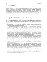
Fig. 3.13 C++ source code for the rgb2ycbcr function
In the C source (Fig. 3.13), the RBG input is modeled as an array of structs.
The rgb
t struct contains three fields: r, g and b. By default, Catapult assumes the
R, G and B components are mapped to three different interface resources. Using
interface synthesis constraints, it is possible to merge them all side-by-side on the
same resource and map this resource to a memory.
This way, the color space conversion block will get all its input from a single
memory, with every read returning all three R, G and B color components over a
3 ×8 = 24 bit data bus (Fig. 3.14).
The function itself is pipelined with an initiation interval of 1, to create a con-
tinuously running design with a throughput of 1 memory access per cycle. By the
same effect, outputs will be produced at a constant rate of one sample per cycle.
3 Catapult Synthesis: A Practical Introduction to Interactive C Synthesis 47
Fig. 3.14 Mapping side-by-side R, G and B pixels in a memory
Fig. 3.15 Gantt chart of the horizontal DCT – throughput 1 sample per cycle
3.4.4 The DCT Block
The DCT is based on a standard 2D 8 ×8 Chen implementation. It decomposes in
a vertical and a horizontal pass, with a transpose buffer in between. In this datapath
dominated design, it easily possible to explore different micro-architectures to
trade-off performance (latency and throughput) versus the number of computational
resources such as adders or multipliers.
The smallest implementation allowing a constant throughput of one sample per
cycle can be scheduled with only 2 multipliers and 6 adders, and has an overall
latency of 82 cycles to process a full 8×8 block. Figure 3.15 shows a partial view
of the corresponding Gantt chart. The left column lists the resources used to build
the micro-architecture. The right part shows how and when these operators are used
to cover specific operations from the reference algorithm. The Gantt chart shows
that the two multipliers are time-shared to implement 16 different multiplications.
Similarly, the six adders implement 48 different additions.
48 T. Bollaert
Fig. 3.16 Catapult XY plot and table of results of the horizontal DCT
Fig. 3.17 C++ source code for the reorder and quantize block
After this first implementation is obtained, the user can easily trade area and
latency through simple scheduling options. With the same throughput requirements,
a design with only 74 cycles of latency can be built with eight adders instead of six.
By increasing or decreasing the throughput constraints, it is possible to further
explore the design space. Figure 3.16 shows the full table of results obtained, as well
as a screenshot of the Catapult built-in XY plot tool used to compare and contrast
the various solutions. The last solution, featuring a throughput of eight samples per
cycles is effectively processing entire rows of the 8 ×8 data set.
3.4.5 The Reorder and Quantize Block
The zigzag reordering and quantization steps are fairly simple. The first step reorders
the DCT results according to a predefined “zigzag” sequence and the second one
quantizes those results based on luminance and chrominance quantization tables.
As shown in Fig. 3.17, these two steps are naturally coded as two sequential
loops, one for each step. Without loop merging, the two loops run sequentially, 135
cycles are required to process a full 8 ×8 block and the throughput is not constant.
3 Catapult Synthesis: A Practical Introduction to Interactive C Synthesis 49
With loop merging, Catapult is able to fold the two sequential loops into a single
one effectively exploiting loop level parallelism. Once properly pipelined, the result
is a continuously running design which simultaneously reorders and quantizes data
at a constant rate of one sample per cycle and with a latency of only 67 cycles for a
full block.
3.4.6 The Huffman Encoder Block
Compared to the other blocks in the JPEG pixel pipe, the Huffman encoder is much
more of a control-oriented, decision making algorithm. The run-length part of the
encoder scans values as they arrive, counting the number of consecutive zeros.
When a non-zero value is found, it is paired with the number of preceding zeros.
This pair of symbols is then Huffman encoded, forming a bitstream of codewords
(Fig. 3.18). In the C program, the function returns the bitstream as an array of struct.
Catapult interface synthesis directives are used to build a streaming interface with
Fig. 3.18 C++ source code for the run-length encoder
50 T. Bollaert
handshake. Every cycle the encoder outputs a codeword with an additional flag,
indicating whether the current output data is valid or not.
3.4.7 Integrating the Hierarchical System
When performing top-down hierarchical synthesis, Catapult starts by independently
synthesizing each of the four sub-functions. Then Catapult integrates all the sub-
blocks, building the appropriate inter-block communication and creating the needed
synchronization logic. Top-level control structures are synthesized to guarantee safe
and efficient data exchange between blocks.
When two blocks exchange data through an array, Catapult distinguishes two
cases, depending if the producer and consumer access the array in the order or not.
If they do, then a streaming communication can be synthesized. If the two blocks
access the array in different order, then intermediate storage is required to allow the
two blocks to run in parallel. Catapult can automatically build ping-pong memories,
round robin memories and other kinds of interleaved structures.
In our JPEG encoder, the array written by the quantization block and read by
the Huffman encoder is accessed in the same order by blocks, from index 0 up to
63, with constant increments. Catapult will therefore build a streaming connection
between both blocks.
However, while the DCT outputs results from index 0 up to 63, the reordering
block reads those values in a zigzag order. In this case intermediate storage will be
required, for instance in the form of a ping-pong buffer and its associated control
and synchronization logic (Fig. 3.19).
3.4.8 Generating the Design
Catapult outputs VHDL, Verilog and SystemC netlists, both RTL and behavioral, as
well as various scripts and makefile needed to use the design in various simulation
and synthesis tools.
Fig. 3.19 Hardware integration and communication architecture of the JPEG encoder
3 Catapult Synthesis: A Practical Introduction to Interactive C Synthesis 51
Fig. 3.20 Instrumented testbench for automatic verification
In this example, once all the constraints are set, it takes a little over 3 min
of synthesis runtime, on an average workstation, to produce the desired design
implementation, turning 469 lines of C++ code modeling the JPEG encoder into
11,200 lines of RTL VHDL.
3.4.9 Verifying the RTL
Once the RTL is generated, Catapult provides a push-button verification flow allow-
ing simulation of the generated design against the original design and testbench.
For this matter the testbench calling the synthesized C function should be instru-
mented to call the verification infrastructure instead of just the reference algorithm
when running the automatic verification flow (Fig. 3.20).
Besides this simple change, the rest of the flow is fully automated and the user
simply needs to run the Catapult generated makefile which will take core of com-
piling and linking the proper C, SystemC and HDL design files within the specified
simulation environment.
The difference in simulation performance between the C design and the equiva-
lent RTL gives another good idea of the benefits of designing in C instead of HDL.
In this example, a trivial testcase which runs in a 1/10th of a second, runs in about
2:30min on an average workstation, showing a 1,500× difference. Not only edits
are more quickly done in C than in HDL, they can also be much more rapidly and
thoroughly verified.
3.5 Conclusion
In this paper, we gave in depth overview of Catapult Synthesis, an interactive C
synthesis tool which generates production quality results up to 20× fasters than
with manual approaches.
While much debate has occurred about the applicability and the maturity of
behavioral synthesis tools, the success of Catapult in the market place and its
endorsement by leading semiconductor vendors demonstrate the viability of this
design methodology which is now clearly used beyond the traditional circle of
visionaries and early adopters.
52 T. Bollaert
This success was built on state-of-the-art technology, resulting from many
man/years of internal research and development. But synthesizing RTL from
abstract specifications is not an end in itself. There far more other real-life con-
straints which technology-alone doesn’t address. Mentor Graphics and the Catapult
Synthesis team have always recognized the importance of complying with indus-
trial requirements, such as integration in flows, vendor sign-off, risk-management,
knowledge transfer, reliable support and, last but not least, clear ROI.
Acknowledgments The author would like to acknowledge the Catapult Synthesis team, and
most specifically, Bryan Bowyer, Andres Takach and Shawn McCloud for their direct or indirect
contributions to this work.
Chapter 4
Algorithmic Synthesis Using PICO
An Integrated Framework for Application
Engine Synthesis and Verification from High
Level C Algorithms
Shail Aditya and Vinod Kathail
Abstract The increasing SoC complexity and a relentless pressure to reduce time-
to-market have left the hardware and system designers with an enormous design
challenge. The bulk of the effort in designing an SoC is focused on the design of
product-defining application engines such as video codecs and wireless modems.
Automatic synthesis of such application engines from a high level algorithmic
description can significantly reduce both design time and design cost. This chap-
ter reviews high level requirements for such a system and then describes the PICO
(Program-In, Chip-Out) system, which provides an integrated framework for the
synthesis and verification of application engines from high level C algorithms.
PICO’s novel approach relies on aggressive compiler technology, a parallel exe-
cution model based on Kahn process networks, and a carefully designed hardware
architecture template that is cost-efficient, provides high performance, and is sen-
sitive to circuit level and system level design constraints. PICO addresses the
complete hardware design flow including architecture exploration, RTL design, RTL
verification, system validation and system integration. For a large class of modern
embedded applications, PICO’s approach has been shown to yield extremely com-
petitive designs at a fraction of the resources used traditionally thereby closing the
proverbial design productivity gap.
Keywords: SoC design, ASIC design, ESL synthesis, Algorithmic synthesis, High
level synthesis, Application engine synthesis, C-to-RTL, PICO, Architecture explo-
ration, Soft IP, Kahn process networks, System integration, Software drivers, Sys-
tem modeling, System validation, Transaction level models, Task level parallelism,
Instruction level parallelism, Pipeline of processing arrays, Data streams, RTL
verification, Co-simulation, Reusable hardware interfaces
P. Coussy and A. Morawiec (eds.) High-Level Synthesis.
c
Springer Science + Business Media B.V. 2008
53
54 S. Aditya and V. Kathail
4.1 Introduction
The recent explosion in consumer appliances, their design complexity, and time-
to-market pressures have left the system designers facing an enormous design
productivity gap. System and register-transfer level (RTL) design and verification
are increasingly the bottleneck in the overall product cycle. The EDA community
has been trying to get around this bottleneck for over a decade, first with behavioral
synthesis [1], and then with intellectual property (IP) reuse [2]. However, both those
approaches have their limitations. In general, behavioral synthesis is a very diffi-
cult problem and has yielded poor cost and performance results compared to hand
designs. IP reuse, on the other hand, has worked to a limited extent in System-on-
Chip (SoC) designs, where standard IP blocks on a common embedded platform
may be shared across various generations of a product or even across families of
products.
A typical platform SoC comprises four different types of IP as shown in Fig. 4.1.
These are:
1. Star IP such as CPUs and DSPs: Star IP needs significant investment in terms of
building the hardware, the software tool chain as well as the creation, debugging
and compatibility of operating system and application software. This type of IP
is usually designed manually, doesn’t often change, and is very hard to alter
when it does. Therefore, this IP is typically reused across several generations
of a product.
2. Complex application engines such as video codecs and wireless modems: These
IP blocks are critical for differentiating the end product and change rapidly with
each revision in functionality, target technology, or both. Additionally, signifi-
Fig. 4.1 An SoC embedded platform with application engines
4 Algorithmic Synthesis Using PICO 55
cant investment is continually being made to improve their power, performance
and area across product generations. Therefore, direct reuse of this IP is quite
limited.
3. Connectivity and control IP such as USB port and DMA: This is system level
glue that never defines the functionality nor differentiates the end product. This
IP, therefore, is typically reused to reduce cost and provide standardization. It
does sometimes need a limited amount of tailoring.
4. Memory: Memory takes up the largest amount of silicon area, but also neither
defines the function nor differentiates the end product. Memories are almost
always compiled and built bottom-up. Their models are generated from the
transistor level behavior.
Each of these different types of IP needs to be integrated into an SoC. The avail-
ability of standard interfaces (memory, streaming, bus) based on industry standard
protocols, such as OCP [3], make this integration more straightforward.
Unlike other IP elements of the platform SoC, IP reuse of product-defining
application engines is hard because every new product context requires some spe-
cialization and adaptation to meet the new design objectives. For this reason, and
because they critically define the SoC functionality, the bulk of the SoC design effort
is focused on the design and verification of application engines.
4.1.1 Application Engine Design Challenges
Complex application engines such as multi-standard codec and 3 G wireless modems
used in the next generation consumer devices place extreme requirements on their
designs – they require very high performance at very low power and low area. For
example, software defined radio for 4 G wireless modem requires 10–100 GOPs
(giga operations per second) at a budget of 100–500 mW of power [4] – that is,
about 100 MOPs mW
−1
. Off-the-shelf solutions such as general-purpose processors
or DSPs cannot satisfy such extreme requirements. Embedded DSPs are unable to
provide the high performance. On the other hand, high end DSPs such as IBM Cell
processor can provide the high performance but their power consumption is very
high (in the 10MOPs mW
−1
range).
The solution is to build application-specific or custom processors, or dedicated
hardware systems to meet the extreme performance-power-area goals. Typically,
direct hardware implementations can achieve 100–1,000MOPs mW
−1
and provide
2–3 orders of magnitude better area and power compared to embedded processors
or DSPs.
Customization, however, has its cost. Manual design of application engines using
current design methodologies is very expensive in terms of both design time and
non-recurring engineering (NRE) cost leading to SoCs that take millions of dollars
and years to design. This is not sustainable for two reasons. First, SoCs are growing
in complexity because of the insatiable demand for more and more features and