High Level Synthesis: from Algorithm to Digital Circuit- P11 potx
Bạn đang xem bản rút gọn của tài liệu. Xem và tải ngay bản đầy đủ của tài liệu tại đây (247.74 KB, 10 trang )
86 M. Meredith
{
bind(c);
}
};
Note that the addition of these functions allows the binding to be done using the
conventional SystemC port binding syntax:
socket.bind(channel);
or
socket(channel);
Also note that the binding functions are defined as templates. This lets the same
ports and binding functions to be used for port-to-port binding in a hierarchical
design.
5.6 Structural Hierarchy
In addition to the process control constructs, SystemC synthesis supports the Sys-
temC constructs for construction of structural hierarchies. An engineering team can
attack a large design problem using structural decomposition, breaking the problem
down into multiple smaller modules that communicate through user-defined inter-
faces. Individual sub-modules can be assigned to different team members if desired
supporting a conventional team structure and concurrent design approach. Each
module can contain any number of cooperating SC
CTHREADs, SC METHODs,
and sub-modules. Communication between modules is achieved using a port-to-
signal binding mechanism of a kind that is familiar to RTL designers, or even
designers using schematics.
Here is an example of a hierarchical design using modular interfaces as described
previously.
SC
MODULE(parent)
{
// ports
sc
in clk clk;
sc
in<bool> rst;
RV
in< sc uint<8> > din;
RV
out< sc uint<8> > dout;
// submodules
sub
module m sub1;
sub
module m sub2;
5 High-Level SystemC Synthesis with Forte’s Cynthesizer 87
// signals and channels
RV< sc
uint<8> > chan;
SC
CTOR(parent)
:m
sub1("sub1"),
m
sub2("sub2"),
chan("chan")
{
// bind first module using bind() function
m
sub1.clk.bind(clk);
m
sub1.rst.bind(rst);
m
sub1.din.bind(din); // socket-to-socket
m
sub1.dout.bind(chan); // socket-to-channel
// bind second module using socket() syntax
m
sub2.clk(clk);
m
sub2.rst(rst);
m
sub2.din(chan);
m
sub2.dout(dout);
}
};
This use of SystemC constructs rather than tool constructs for implementation
of hierarchy and communication improves the overall verification process dramat-
ically. The complete structural hierarchy can be simulated at a behavioral level,
accurately representing the concurrency of all the modules and threads, and accu-
rately verifying the pin-level communication protocols between them. This allows
the functional verification to be performed using high-speed behavioral simulation,
and eliminates the need for many slow RTL simulations.
5.7 Creating RTL with Predictable Timing Closure
One of the challenges in RTL design is to ensure that the RTL you have written will
have successful timing closure through logic synthesis at the specified clock rate
when implemented in the chosen process technology. High-level synthesis has to
meet the same challenge to be practical for wide deployment.
Cynthesizer achieves this by combining a number of steps. First, the timing infor-
mation about the cells in the target process technology library are used as an input
to the high-level synthesis process. This information is read in a Liberty format .lib
file provided by the chosen foundry.
Second, Cynthesizer has advanced datapath optimization technology that it uses
to build a library of gate-level functional units such as adders, multipliers, mul-
tiplexors, etc based on the cells available in the target technology .lib file. These
88 M. Meredith
functional units are optimized for a specific clock frequency, and may be imple-
mented in a pipelined manner, where each pipeline stage is designed to fit within
the designated clock period.
Functional unit library compilation is performed in advance of high-level synthe-
sis once per process technology and clock period to speed the synthesis process. All
the tools needed for library compilation to be performed by the user are included
with Cynthesizer. No additional tool needs to be purchased.
Cynthesizer also creates custom functional units as needed during high-level syn-
thesis. These include non-square parts (i.e., a 12-bit by 3-bit adder) as well as parts
to implement more complex expressions. Cynthesizer automatically identifies use-
ful expressions in the algorithm of the design (such as “a+(b ∗c)−3)” and builds
gate-level parts on the fly that implement them.
Third, Cynthesizer uses this detailed timing information when it schedules the
operations of the algorithm to ensure that no combinatorial path in use exceeds
the clock period. Additional user controls are available to allow the user to adjust
the “aggressiveness” with which Cynthesizer fills each clock period with logic.
These controls can be used to make downstream timing closure even easier, thereby
reducing processing time in downstream tools such as logic synthesis.
Cynthesizer produces RTL produced that has a structural character. Adders, mul-
tipliers, multiplexors, etc are instantiated with a finite state machine determining
what values are presented to each instantiated part in each clock cycle. This ensures
that the timing assumptions made during high-level synthesis are maintained during
logic synthesis.
5.8 Scheduling
It has been noted that a primary benefit of using behavioral synthesis is the abil-
ity to write clocked processes whose functionality takes more than one clock cycle.
This gives the user the ability to control the latency and throughput of the result-
ing circuit without performing detailed resource assignment and scheduling by
hand.
At the same time, I/O activity at the ports of the module being synthesized must
conform to a specified protocol in order to have the synthesized block interoperate
with other blocks. The protocol mandates that certain relationships between I/O
events must be held constant. For instance, the data value must be presented on the
data bus in the same cycle as the data
valid line is driven to true.
5.8.1 Mixed-Mode Scheduling
Cynthesizer addresses these requirements by providing a number of directives
that give the user high-level control of its scheduling. The Cynthesizer scheduler
5 High-Level SystemC Synthesis with Forte’s Cynthesizer 89
allows different code blocks in a single SC CTHREAD to be scheduled differently
according the user requirements. A “code block” is defined as any section of C++
code delimited by “{”and“}.” Thus it can be a clause of an if-else statement, the
body of a loop, or any other set of statements that the user chooses to group together.
Note that while the protocol can be written in-line as it is shown here, protocols
are typically encapsulated into modular interface classes for ease-of-use and for
ease-of-reuse.
SC_MODULE
SC_CTHREAD
Fixed
Context
Unconstrained scheduling
Context
while (1) {
. . .
{ CYN_PROTOCOL(“name1”);
. . . // Get inputs
}
. . . // algorithm
{ CYN_PROTOCOL(“name2”);
. . . // Write output
}
. . .
}
Fixed
Context
5.8.2 Unconstrained Scheduling
To begin with, it is assumed that all the code in the design, unless otherwise iden-
tified, is completely untimed, and that the scheduler of the high-level synthesis
process has complete freedom to implement the functionality in as many or as
few clock cycles as it chooses. No guarantees of any cycle-by-cycle timing are
made in this unconstrained code, although the order of operations determined by
the dependency relationships within the code is maintained.
By default, without any scheduling constraints, Cynthesizer will optimize for
area, taking as many cycles as necessary to complete the computation with a
minimal set of functional units.
90 M. Meredith
5.8.3 Scheduling for Protocol Accuracy
In order to give the user maximum control of cycle-by-cycle timing for implement-
ing protocols, Cynthesizer allows the specification of cycle-accurate blocks of code
by the use of the CYN
PROTOCOL directive. This directive, associated with a par-
ticular code block directs Cynthesizer not to insert any clock cycles within that code
block except for those specified by the user with wait() statements. Within these
protocol blocks, scheduling ensures that the ordering of port and signal I/O and the
given wait()s is held constant.
For some kinds of designs, such close scheduling control is needed that it is
desirable to apply a CYN
PROTOCOL directive to the entire body of the while(1)
loop that implements the bulk of behavior of the SC
CTHREAD. In this case the
user precisely specifies the cycle-by-cycle I/O behavior of the design. Even with this
tight control, the user benefits from using high-level synthesis because the design is
expressed without an explicit FSM designed by the user. In many cases Cynthesizer
can schedule computations and memory accesses within the constraints of the I/O
schedule as well.
5.8.4 Constraining Scheduling
Scheduling can be constrained to achieve specific latency targets by applying a
CYN
LATENCY directive to a specific code block. This directs the scheduler to
ensure that the behavior of the given block is to be scheduled within the number
of cycles specified by the directive. The user is allowed to specify a minimum and
maximum latency to be achieved.
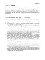
For example, consider the following design which reads in six data values and
outputs a computed result. The data is expressed as a structure:
struct data
struct;
{
sc
uint<8> A;
sc
uint<8> B;
sc
uint<8> C;
sc
uint<8> D;
sc
uint<8> E;
sc
uint<8> F;
sc
uint<8> G;
}
The module has a modular interface input port and a modular output port:
RV
IN<data struct> in port;
RV
OUT< sc uint<28> > out port;
5 High-Level SystemC Synthesis with Forte’s Cynthesizer 91
The main while loop of the SC CTHREAD is:
while( true )
{
sc
uint<28> X;
// read the data from the input port
struct data
struct data = in port.get();
{
// do the computation in 4 cycles
CYN
LATENCY( 4, 4, "algorithm latency" );
X=(A+B+C)
*
(D+E+F)
*
G;
}
// write the result to the output port
out
port.put(X);
}
This can be implemented by Cynthesizer using two adders and one multiplier to
perform this computation in the specified four cycles using the following schedule.
This produces an overall throughput of one value per six cycles.
+
A
B
C
D
E
F
G
*
+
+
+
*
out
12345
in
in
in
in
in
in
in
6
If, on the other hand a slower circuit were acceptable, a 6-cycle latency for the
computation (resulting in an overall throughput of one value per eight cycles) could
be achieved by specifying:
CYN
LATENCY( 6, 6, "algorithm latency" );
92 M. Meredith
+
*
+
+
+
*
12345 7
out
A
B
C
D
E
F
G
in
in
in
in
in
in
in
68
Cynthesizer could achieve this with the following schedule.
Note that Cynthesizer would automatically produce a new FSM and datapath to
meet the desired latency without the user rewriting the algorithm.
Also note that this example is extremely simplified. In reality, more than one
operation will often be chained within a single clock cycle depending on the rela-
tionships between the required latency, the clock period, the propagation delay
through the adders and multipliers and their relative sizes. For instance, if the clock
cycle were long enough, and the target process technology were fast enough the
design could be scheduled in a single cycle using four adders and two
multipliers.
CYN
LATENCY( 1, 1, "algorithm latency" );
5.9 Loops
Unlike RTL, where loops are seldom used, looping constructs are common in
high-level design. These include loops with non-constant bounds, where the loop
termination condition depends on the state of the design and the input data, as well
as simple for-loops with constant bounds.
5.9.1 Supported Loop and Loop Termination Statements
Cynthesizer supports loops of all forms in the SystemC input code. All the C++
loop statements may be used:
5 High-Level SystemC Synthesis with Forte’s Cynthesizer 93
• “for” loops
• “while” loops
• “do/while” loops
The “continue” and “break” statements may be freely used for loop termination
if desired.
5.9.2 Directives for Loop Control
Loops can be handled in three ways depending on the parallelism desired by the
user.
5.9.3 Default Loop Implementation
The default behavior is for Cynthesizer to implement a loop as a looping structure
in the finite-state machine that is built in the synthesized RTL. In this case there
will be at least one cycle per iteration of the loop. This will introduce the minimum
parallelism with the one instance of the needed hardware being used over and over
for each iteration of the loop.
5.9.4 Unrolling
Unrolling a loop creates additional copies of the hardware that implements the loop
body. These copies can operate in parallel, performing the computation of several
iterations of the loop at the same time.
Loop unrolling is controlled using the CYN
UNROLL directive. The simplest
form of the directive
CYN
UNROLL(ON,"tag");
specifies that the loop be completely unrolled. As a convenience, ALL can be
specified to completely unroll an entire loop nest.
CYN
UNROLL( ALL, "tag" )
For example the following would result in four multipliers being used.
for ( int i = 0; i < 4; i++ )
{
CYN
UNROLL( ON, "example loop" );
array[i] = array[i]
*
10;
}
94 M. Meredith
As if it had been written as follows:
array[0] = array[0]
*
10;
array[1] = array[1]
*
10;
array[2] = array[2]
*
10;
array[3] = array[3]
*
10;
Loops can also be partially unrolled, creating parallel hardware for fewer than the
total number of iterationsof the loop using the directive of the form:CYN
UNROLL
(CONSERVATIVE, N, “tag”);
So, the following loop
for ( int i = 0; i < 4; i++ )
{
CYN
UNROLL( CONSERVATIVE, 2, "example loop" );
array[i] = array[i]
*
10;
}
Would be implemented as if it had been written as follows:
for ( int i = 0; i<2; i = i + 2 )
{
array[i] = array[i]
*
10;
array[i + 1] = array[i + 1]
*
10;
}
5.9.5 Pipelining
Cynthesizer can automatically perform loop pipelining. This can be applied to any
loop within the design. Pipelining the implementation of an entire thread can be
accomplished by applying the pipelining directive to the while(1) loop that consti-
tutes the bulk of the thread behavior. Consider our earlier example scheduled with a
computational latency of 4. Recall that this consumed two adders and one multiplier
to produce a throughput of one value each six cycles.
We could pipeline this earlier example as follows.
while(true)
{
CYN
INITIATE( CONSERVATIVE, 2, "main loop" );
struct data
struct data = in port.get();
sc
uint<28> X = (A + B + C)
*
(D+E+F)
*
G;
out
port.put(X);
}
5 High-Level SystemC Synthesis with Forte’s Cynthesizer 95
This constrains the synthesis schedule to initiate a new iteration of the loop every
two cycles. This would result in the following schedule.
+
A
B
C
D
E
F
G
*
+
+
+
*
out1
12345
in1
6
in1
in1
in1
in1
in1
in1
+
A
B
C
D
E
F
G
*
+
+
+
*
out2
in2
in2
in2
in2
in2
in2
in2
78
Note that the maximum resource utilization occurs beginning in cycle 4 where
two adders and one multiplier are used. By pipelining the design, we are able to
achieve a throughput of two values every eight cycles without using any addi-
tional multipliers or adders. This is a 50% increase in throughput with no increase
in computing resources. Note again, this is done without any need to recode the
algorithm.
5.10 Verification
The key verification advantage of SystemC high-level synthesis using Cynthesizer
is that the designer is able to:
• Design at a high level
• Verify the algorithm and the interface protocols using high-speed behavioral
simulation