High Level Synthesis: from Algorithm to Digital Circuit- P17 docx
Bạn đang xem bản rút gọn của tài liệu. Xem và tải ngay bản đầy đủ của tài liệu tại đây (394.75 KB, 10 trang )
148 P. Coussy et al.
RTL. Designers will spend more time exploring the design space with multiple
“what if” scenarios. They will obtain a range of implementation alternatives, from
which they will select the architecture providing the best power/speed/gate count
trade-off.
This chapter presents GAUT which is an open-source HLS tool dedicated to
DSP applications [1]. Starting from an algorithmic bit-accurate specification writ-
ten in C/C++, a throughput constraint (Initiation Interval) and a clock period, the
tool extracts the potential parallelism before processing the selection, the allocation,
the scheduling and the binding tasks. GAUT generates a potentially pipelined archi-
tecture composed of a processing unit, a memory unit and a communication unit.
Several RTL VHDL models for the logic synthesis and SystemC CABA (Cycle
Accurate Bit Accurate) and TLM-T (Transaction Level Model with Timing) are
automatically generated with their respective test benches.
The chapter is organized as follow: Sect. 9.2 introduces our design flow and
presents the targeted architecture. Section 9.3 details each step of our high-level
synthesis flow. In Sect. 9.4, experimental results are provided.
9.2 Overview of the Design Environment
High-level synthesis enables the (semi) automatic search for architectural solutions
that respect the specified constraints while optimizing the design objectives. To be
efficient, the synthesis must rely on a design method which takes into account the
specificity of the application fields. We have focused on the domain of real-time
digital signal processing and we have formalized a dedicated design approach for
this type of application where the regular and periodic data-intensive computations
dominate.
GAUT [1] takes as input a C description of the algorithm that has to be synthe-
sized. The mandatory constraints are the throughput (specified through an initiation
interval which represents the constant interval between the start of successive iter-
ations) and the clock period. Optional design constraints are the memory mapping
and I/O timing diagram. The architecture of the hardware components that GAUT
generates is composed of three main functional units: a processing unit PU, a mem-
ory unit MEMU and a Communication & Interface Unit COMU (see Fig. 9.1). The
PU is a datapath composed of logic and arithmetic operators, storage elements,
steering logic and a controller (FSM). Storage elements of the PU can be strong
semantic memories (FIFO, LIFO) and/or registers. The MEMU is composed of
memory banks and their associated controllers. The COMU includes a synchroniza-
tion processor and an operation memory which allow to have a GALS/LIS (Globally
Asynchronous Locally Synchronous/Latency Insensitive System) communication
interface.
As described in Fig. 9.2, GAUT first synthesizes the Processing Unit. Then it gen-
erates the Memory Unit and the Communication Unit. During the design of the PU,
GAUT initially selects arithmetic operators and after targets their best use according
to the design constraints and objectives. Then GAUT processes the registers and
9 GAUT: A High-Level Synthesis Tool for DSP Applications 149
Port OUT
Synchronization
processor
Synchronization
processor
Operation memory
Operation memory
Not
empty
Pop
Push
Not
full
Enable
Clock
Port IN
Port OUT
FIFO
LIFO
Registers
FSM controller
RAM Block #1
Gen_@
FSM
RAM
multiplier
adder
Operation word
Operation address
Memory Unit
MEMU
Processing
Unit PU
Communication
Unit COMU
Fig. 9.1 Target architecture
Analysis
DFG
C/C++ Specification
Compilation
Constraints
Characterization
Function
library
PU synthesis
MEMU synthesis
COMU synthesis
VHDL RTL
Architecture
SystemC Simulation
Model
(CABA/TLM-T)
- Throughput
- Clock period
- Memory mapping
- I/O timing diagram
Allocation
Scheduling
Optimization
Binding
Resizing
Clustering
Component
library
Fig. 9.2 Proposed high-level synthesis flow
150 P. Coussy et al.
memory banks, which are part of the memory unit. The register’s optimization,
which is done before the memory optimization, is based on prediction techniques.
The communication paths will then be optimized, followed by the optimization of
the address generators of the memory banks dedicated to the application being con-
sidered. The communication interface is generated next by using the I/O timing
behavior of the component. To validate the generated architecture, a test bench is
automatically generated to apply stimulus to the design and to analyze the results.
The stimulus can be incremental, randomized or user defined values allowing auto-
matic comparison with the initial algorithmic specification (i.e. the “golden” model).
The processing unit can be verified alone. In this case, the memory and communi-
cation units are generated as VHDL components whose behavior is described as
a Finite State Machine with Data path. GAUT generates not only VHDL models
but also scripts necessary to compile and simulate the design with the Modelsim
simulator. It can also compare the results of two simulations (produced by different
timing behaviors (I/O, pipeline. )). Both “Cycle Accurate, Bit Accurate” (CABA)
and “Transaction-Level Model with Timing” (TLM-T) simulation models are gen-
erated which allow to integrate the components into the Soclib platform [1]. GAUT
also addresses the design of multi-mode architectures (see [3] for details).
9.3 The Synthesis Flow
9.3.1 The Front End
The input description is a C/C++ function where Algorithmic C
TM
class library
from Mentor Graphics [5] is used. This allows the designer to specify signed and
unsigned bit-accurate integer and fixed-point variables by using ac
int and ac fixed
data types. This library, like SystemC [6], hence SystemC [6], hence provides fixed-
point data-types that supply all the arithmetic operations and built-in quantization
(rounding, truncation )andoverflow(saturation,wrap-around )functionalities.
For example, an ac
fixed <5,2,true,AC RND,AC SAT> is a signed fixed-point num-
ber of the form bb.bbb (five bits of width, two bits integer) forwhich the quantization
and overflow modes are respectively set to ‘rounding’ and ‘saturation’.
9.3.1.1 Compilation
The role of the compiler is to transform the initial C/C++ specification into a for-
mal representation which exhibits the data dependencies between operations. The
compiler of GAUT derives gcc/g++ 4.2 [7] to extract a data flow graph (DFG)
representation of the application annotated with the bit-width information (the code
optimizations performed by the compiler will not be presented in this paper). For the
quantization/overflow functionality of a fixed-point variable, the compiler generates
dedicated operation nodes in the DFG. As described later, this allows to share
(i.e. reuse) (1) arithmetic operators between bit-accurate integer operations and
9 GAUT: A High-Level Synthesis Tool for DSP Applications 151
fixed-point operations and (2) quantization/overflow operators between fixed-point
operations. Timing performance optimization is addressed through the operator
chaining.
As detailed in [7], the gcc/g++ compiler includes three main components: a
front end, a middle end and a back end. The front end performs lexical, syntacti-
cal and semantic analysis on the code. The middle end operates code optimizations
on the internal representation named “GIMPLE”. The back end performs hardware
dependent optimizations and finally generates assembly language. The source file
is processed in four main steps: (1) the C preprocessor (cpp) expands the prepro-
cessor directives; (2) the front end constructs the Abstract Syntax Tree (AST) for
each function of the source file. The AST tree is next converted into a CDFG-
like unified form called GENERIC which is not suitable for optimization. The
GENERIC representation is lowered into a subset called GIMPLE form; (3) false
data dependencies are eliminated with Static Signal Assignment and various scalar
optimizations (dead code elimination, value range propagation, redundancy elimi-
nation). Loop optimizations (loop invariant, loop peeling, loop fusion, partial loop
unrolling) are applied; (4) finally the GIMPLE form is translated into the GAUT
internal representation.
9.3.1.2 Bit-Width Analysis
The bit-width analysis which next operates on the DFG is based on the two
following steps:
• Constant bit-width definition: the compiler carries out a DFG representation
where the constants are represented by nodes with a 16, 32 or 64 bit size. This
first analysis step defines for each constant the exact number of bits needed to
represent its value. We use the simple following formula for unsigned and signed
values:
Number of bits = log
2
|Value|+ 1+ S
igned
.
• Bit-width and value range propagation: infers the bit-width of each variables
of the specification by coupling work from [9] and [10]. A bit-width analysis
is hence performed to optimize the word-length of both the operations and the
variables. This step performs a forward and a backward propagation of both the
value ranges and the bit-width information to figure out the minimum number of
bits required.
9.3.1.3 Library Characterization
Library characterization uses a DFG, a technological library and a target technology
(typically the FPGA model). This fully automated step, based on commercial logic
synthesis tools like ISE from Xilinx and Quartus from Altera, produces a library of
time characterized operators to be used during the following HLS steps. The techno-
logical library provides the VHDL behavioral description of operators and the DFG
152 P. Coussy et al.
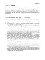
Fig. 9.3 Propagation time
vs. bit-width for addition-
subtraction and multiplication
operations
Propagation time
0
2
4
6
8
10
12
14
16
18
20
22
24
2 4 6 8 10 12 14 16 18 20 22 24 26 28 30 32
Inputs Bitw idth
ns
Add
Mul
Fig. 9.4 Multiplier area vs.
bit-width
0
50
100
150
200
250
300
350
2 4 6 8 10 12 14 16 18 20 22 24 26 28 30 32
Inputs Bitw idth
slices
Fig. 9.5 Adder area vs.
bit-width
0
2
4
6
8
10
12
14
16
18
2 4 6 8 10 12 14 16 18 20 22 24 26 28 30 32
Inputs Bitw idth
slices
provides the set of operations to be characterized with their bit-width information.
The characterization step synthesizes each operator from the technological library
which is able to realize one operation of the DFG. It next retrieves synthesis results
in terms of logical cell number and propagation time to generate a characterized
operator library. Figures 9.3–9.5 present results provided by the characterization
step.
9.3.1.4 Operation Clustering
For clustering operations we propose to combine the computational function and the
operation delay. This allows to indirectly consider operation’s bit-width since the
propagation time of an operator depends on its operand’s size. In order to maximize
9 GAUT: A High-Level Synthesis Tool for DSP Applications 153
the use of operators, one operation that belongs to a cluster C1 with a propagation
time t1 can be assigned to operators allocated for a cluster C2 if the propagation
time t2 is greater than t1.
9.3.2 Processing Unit Synthesis
The design of the Processing Unit (PU) integrates the following tasks: resource
selection and allocation, operation scheduling, and binding of operations onto
operators. First, GAUT executes the allocation task, and then executes the schedul-
ing and the assignment tasks (see Figs. 9.2 and 9.6).
Inputs:
DFG, timing constraint and resource allocation
Output:
A scheduled DFG
Begin
cstep = 0;
Repeat until the last node is scheduled
Determine the ready operations RO;
Compute the operations mobility;
While there are RO
If there are available resources
Schedule the operation with the highest priority;
Remove resource from available resource set;
If the current operation belongs to a chaining pattern
Update the ready operations RO;
If there are available resources
Schedule the operations corresponding to the pattern;
Remove resources from available resource set;
End if
End if
Else
If the operations can be delayed
Delay the operations;
Else
Allocate resources (FUs);
Schedule the operations;
End if
End if
End while
Bind all the scheduled operations;
cstep++;
End
Fig. 9.6 Pseudo code of the scheduling algorithm
154 P. Coussy et al.
9.3.2.1 Resource Allocation
Allocation defines the type and the numbers of operators needed to satisfy the design
constraints. In ourapproach, in order to respect the throughputrequirement specified
by the designer, allocation is done for each a priori pipeline stage. The number of a
priori pipeline stage is computed as the ratio between the minimum latency, Latency,
of the DGF (i.e. the longest data dependency path in the graph) and the Initiation
Interval II (i.e. the period at which the application has to (re)iterate): Latency/II.
Thus we compute the average parallelism of the application extracted from the DFG
dated by an As Soon As Possible (ASAP) unconstrained scheduling. The average
parallelism is calculated separately for each type of operation and for each pipeline
stage s of the DGF, comprising the set of the date operations belonging to [s.II,
(s+1).II]. The average number of operators, for a given operation type type,thatis
allocated to an a priori pipeline stage is defined as follow:
avr
opr(type)=
⎡
⎢
⎢
⎢
nb
ops(type)
II
T(opr)
∗
Tclk
II(opr)
⎤
⎥
⎥
⎥
with Tclk the clock period, nb
ops(type) the number of operators of type type that
belong to the current pipeline stage, T(opr) the propagation time of the operator and
II(opr) the iteration period of pipelined operators.
This first allocation is considered as a lower bound. Thus, during the scheduling
phase, supplementary resources can be allocated and pipeline stages may be created
if necessary. This is done subsequently to operation scheduling on the previously
allocated operators.
9.3.2.2 Operation Scheduling
The classical “list scheduling” algorithm relies on heuristics in which the ready
operations (operations to be scheduled) are listed by priority order. An operation
can be scheduled if the current cycle is greater than or equal to its earliest time.
Whenever two ready operations need to access the same resource (this is a so-called
resource conflict), the operation with the highest priority is scheduled. The other is
postponed.
Traditionally, bit-width information is not considered and the priority function
depends on the mobility only. The operation mobility is thus defined as the dif-
ference between the As Late As Possible (ALAP) time and the current c-step (see
Fig. 9.6). In order to optimize the final architecture area, we modified the classical
priority function to take into account the bit-with of the operations in addition to
the mobility. Hence, the priority of an operation is a weighted sum of (1) its timing
priority (i.e. the inverse of its mobility) and (2) the inverse of the over-cost inferred
by the pseudo assignment of the largest operator (returned by the maxsize function)
with the operation.
9 GAUT: A High-Level Synthesis Tool for DSP Applications 155
Priority =
α
mobility
+
1 −
α
over cost(operation,max size(operator))
,
overcost (ops,opr)=Min
⎧
⎨
⎩
opr
in1
− ops
in1
opr
in1
+
opr
in2
− ops
in2
opr
in2
,
opr
in2
− ops
in1
opr
in2
+
opr
in1
− ops
in2
opr
in1
⎫
⎬
⎭
.
The overcost function return the lowest sum of gradients of operation input’s
bit-width and of operator input’s bit-width. This means that for a same mobility,
the priority will be given to the operation that best minimizes the over-cost. For
different mobility, the user defined factor
α
allows to increase the priority of an
operation O
1
having more mobility than an operation O
2
if overcost(O
1
)islessthan
overcost(O
2
). In the over-cost computation, the reuse of an operator (already used)
is avoided through a pseudo-assignment made during the scheduling. A pseudo-
assignment is a preliminary binding which allows to remove the largest operator
from the available resource set.
Once the operations can be no more scheduled in the current cycle, the resource
binding is performed.
Operation Chaining
To respect the specified timing constraints (latency or throughput) while optimiz-
ing the final area, operator chaining can be used. In our approach, the candidate for
chaining are identified by using templates in a library. Through a dedicated specifi-
cation language, the user defines chaining patterns with their respective maximum
delays. These latency constraints are expressed in number of clock cycles which
allows to be bit-width independent in the pattern specification.
In order to allow the sharing of arithmetic operators between bit-accurate and/or
fixed-point operations, the compiler generates for fixed-point operations two nodes
in the DFG: one node for the arithmetic operation and one other for the quantiza-
tion/overflow functionality.
Figure 9.7a depicts a fixed-point dedicated operator where the computational part
is merged with the quantization/overflow functionality. This kind of operator archi-
tecture neither allows to share the arithmetic logic nor the quantization/overflow
+
overflow quantization
overflow
quantization
xy
z
(a) (b) (c)
+
Register
xy
z
overflow quantization
overflow
quantization
+
xy
z
overflow quantization
overflow
quantization
Fig. 9.7 (a) Monolithic fixed-point operator, (b) “Unchained” fixed-point operator and (c)Chained
fixed-point operator
156 P. Coussy et al.
part between bit-accurate and/or fixed-point operations Fig. 9.7b shows the resulting
architecture when the compiler generates dedicated nodes for a fixed-point opera-
tion and when chaining is not used. Figure 9.7c presents an architecture where the
arithmetic part and the quantization/overflow functionality have been chained by
coupling both the compiler results and a fixed-point templates.
9.3.2.3 Resource Binding
The assignment of an available operator with a candidate operation has to respond
to the minimization of interconnections (steering logic) between operators and to
the minimization of the operator’s size. Given the set of allocated Functional Units
FUs, our binding algorithm assigns all the scheduled operations of the current step
(see Fig. 9.6). The pipeline control of each operator is managed by a complementary
priority on assignment. When an operator is allocated, but not yet used, its priority
for assignment is primarily inferior to that of an already bound operator.
The first step consists in constructing a bipartite weighted graph G =(U,FU(V),
E) with:
• U, the set of operations in c-step S
k
of the DFG
• FU(V ), the set of available FUs in c-step S
k
that can implement at least one
operation from V
• E, the set of weighted edges (U,FU(V)) between a pair of operations u ∈U and
a functional unit fu(v) where v ∈V
The edge weight w
uv
is given by the following equation:
w
u,v
=
β
∗con(u,v)+(1−
β
)∗dist(u,v),
where:
• con(u,v) is the maximum number of existing connections between fu(v) and
each FUs assigned to the set of predecessors of u
• dis(u,v) is the reciprocal of the positive difference between bit-widths of u and v
operands
•
β
is user defined factor which allow minimizing either steering logic area or
computational area
The second step consists in finding the maximal weighted edge subset by using
the maximum weighted bipartite matching (MWBM) algorithm described in [8].
Assuming:
• The scheduling and binding of the operations of the DFG in Fig. 9.8a on c-step1
and c-step2, has been already done
• The operations O
1
and O
4
have been scheduled in c-step3
• Allocated operators are SUB
1
, SUB
2
and ADD
1
• O
9
, O
1
have been bound to SUB
1
• O
3
, O
0
have been bound to ADD
1
9 GAUT: A High-Level Synthesis Tool for DSP Applications 157
o
3
o
0
o
1
o
4
o
7
o
9
+
+
-
-
-
+
-
c-step1
c-step2
c-step3
c-step4
O
1
O
4
SUB
1
SUB
2
W
11
=3
W
41
=2
W
42
=0
W
12
=0
O
1
O
4
SUB
1
SUB
2
W
11
=3
W
42
=0
(a)
W
12
=0
W
41
=2
(b)
(c)
o
8
o
3
o
0
o
1
o
4
o
7
o
9
+
+
-
-
-
+
-
c-step1
c-step2
c-step3
c-step4
O
1
O
4
SUB
1
SUB
2
W
11
=3
W
41
=2
W
42
=0
W
12
=0
O
1
O
4
SUB
1
SUB
2
W
11
=3
W
42
=0
(a)
W
12
=0
W
41
=2
(b)
(c)
o
8
Fig. 9.8 (a) DFG example, (b) Bipartite weighted graph, (c) Maximal weighted edge matching
We will focus on O
1
and O
4
binding. Our algorithm first constructs the bipar-
tite weighted graph (Fig. 9.8b) taking
β
equal to 1 for the sake of simplicity (i.e.
only steering logic is considered). Afterwards, the MBWM algorithm is applied to
identify the best edges.
Thus, operation O
1
is assigned to SU B
1
thanks to the edge weight w
11
= 3.
Nodes connected to w
11
are then removed from the bipartite graph and so forward
(Fig. 9.8c). In other word, connection between ADD
1
(FU bound to O
1
predeces-
sor) and SUB
1
is maximized thereby the creation of multiplexers is avoided. Thus
the final architecture has been optimized.
9.3.2.4 Operator Sizing
In this design step the operators have to be sized according to the operations which
have been assigned on. In order to get correct computing results, the width of the
operator inputs/outputs have to be greater or equal to the width of the operation
variables. Operation variables can have different sizes which can greatly impact the
propagation time and the area of the operator.
The input’s width of an operator is used to be the maximum of all its inputs as
described in the available literature (see [9] and and [11] for example). This com-
puting method increases considerably the final area (see Figs. 9.4 and 9.9 and [12]).
However, an operator can have different input width. Thus, the operator sizing task
can optimize the final operator area by (1) computing the maximum width for each
input respectively (Fig. 9.9b) or (2) computing the optimal size for each input by
considering commutativity (Fig. 9.9c). However swapping inputs can infer steering
logic.
Let’s consider a multiplier that executes two operations O
1
and O
2
. Their respec-
tive input widths are (in
1
= 8, in
2
= 4) and (in
1
= 3, in
2
= 9) and output width is 12.
Figure 9.9 shows respectively for each approach the synthesis results we obtained
by using a Xilinx Virtex2 xc2v8000 -4 FPGA device and the ISE 8.2 logic synthesis
tool. Considering different widths for each input can thus reduce the operator area.