Parallel Programming: for Multicore and Cluster Systems- P4 pptx
Bạn đang xem bản rút gọn của tài liệu. Xem và tải ngay bản đầy đủ của tài liệu tại đây (230.93 KB, 10 trang )
20 2 Parallel Computer Architecture
in the cache. If so, the data is loaded from the cache and no memory access is
necessary. Therefore, memory accesses that go into the cache are significantly faster
than memory accesses that require a load from the main memory. Since fast memory
is expensive, several levels of caches are typically used, starting from a small, fast,
and expensive level 1 (L1) cache over several stages (L2, L3) to the large, but slow
main memory. For a typical processor architecture, access to the L1 cache only takes
2–4 cycles whereas access to main memory can take up to several hundred cycles.
The primary goal of cache organization is to reduce the average memory access time
as far as possible and to achieve an access time as close as possible to that of the L1
cache. Whether this can be achieved depends on the memory access behavior of the
program considered, see Sect. 2.7.
Caches are used for single-processor computers, but they also play an important
role in SMPs and parallel computers with different memory organization. SMPs
provide a shared address space. If shared data is used by multiple processors, it
may be replicated in multiple caches to reduce access latencies. Each processor
should have a coherent view of the memory system, i.e., any read access should
return the most recently written value no matter which processor has issued the
corresponding write operation. A coherent view would be destroyed if a processor
p changes the value of a memory address in its local cache without writing this value
back to main memory. If another processor q would later read this memory address,
it would not get the most recently written value. But even if p writes the value back
to main memory, this may not be sufficient if q has a copy of the same memory
location in its local cache. In this case, it is also necessary to update the copy in the
local cache of q. The problem of providing a coherent view of the memory system
is often referred to as cache coherence problem. To ensure cache coherency, a
cache coherency protocol must be used, see Sect. 2.7.3 and [35, 84, 81] for a more
detailed description.
2.4 Thread-Level Parallelism
The architectural organization within a processor chip may require the use of
explicitly parallel programs to efficiently use the resources provided. This is called
thread-level parallelism, since the multiple control flows needed are often called
threads. The corresponding architectural organization is also called chip multipro-
cessing (CMP). An example for CMP is the placement of multiple independent exe-
cution cores with all execution resources onto a single processor chip. The resulting
processors are called multicore processors, see Sect. 2.4.2.
An alternative approach is the use of multithreading to execute multiple threads
simultaneously on a single processor by switching between the different threads
when needed by the hardware. As described in Sect. 2.3.3, this can be obtained by
fine-grained or coarse-grained multithreading. A variant of coarse-grained multi-
threading is timeslice multithreading in which the processor switches between the
threads after a predefined timeslice interval has elapsed. This can lead to situations
where the timeslices are not effectively used if a thread must wait for an event. If
2.4 Thread-Level Parallelism 21
this happens in the middle of a timeslice, the processor may remain unused for the
rest of the timeslice because of the waiting. Such unnecessary waiting times can
be avoided by using switch-on-event multithreading [119] in which the processor
can switch to the next thread if the current thread must wait for an event to occur as
can happen for cache misses.
A variant of this technique is simultaneous multithreading (SMT) which will
be described in the following. This technique is called hyperthreading for some
Intel processors. The technique is based on the observation that a single thread of
control often does not provide enough instruction-level parallelism to use all func-
tional units of modern superscalar processors.
2.4.1 SimultaneousMultithreading
The idea of simultaneous multithreading (SMT) is to use several threads and
to schedule executable instructions from different threads in the same cycle if
necessary, thus using the functional units of a processor more effectively. This
leads to a simultaneous execution of several threads which gives the technique
its name. In each cycle, instructions from several threads compete for the func-
tional units of a processor. Hardware support for simultaneous multithreading is
based on the replication of the chip area which is used to store the processor
state. This includes the program counter (PC), user and control registers, as well
as the interrupt controller with the corresponding registers. With this replication,
the processor appears to the operating system and the user program as a set of
logical processors to which processes or threads can be assigned for execution.
These processes or threads can come from a single or several user programs. The
number of replications of the processor state determines the number of logical
processors.
Each logical processor stores its processor state in a separate processor resource.
This avoids overhead for saving and restoring processor states when switching to
another logical processor. All other resources of the processor chip like caches, bus
system, and function and control units are shared by the logical processors. There-
fore, the implementation of SMT only leads to a small increase in chip size. For two
logical processors, the required increase in chip area for an Intel Xeon processor is
less than 5% [119, 178]. The shared resources are assigned to the logical processors
for simultaneous use, thus leading to a simultaneous execution of logical processors.
When a logical processor must wait for an event, the resources can be assigned to
another logical processor. This leads to a continuous use of the resources from the
view of the physical processor. Waiting times for logical processors can occur for
cache misses, wrong branch predictions, dependencies between instructions, and
pipeline hazards.
Investigations have shown that the simultaneous use of processor resources by
two logical processors can lead to performance improvements between 15% and
30%, depending on the application program [119]. Since the processor resources are
shared by the logical processors, it cannot be expected that the use of more than two
22 2 Parallel Computer Architecture
logical processors can lead to a significant additional performance improvement.
Therefore, SMT will likely be restricted to a small number of logical processors.
Examples of processors that support SMT are the IBM Power5 and Power6 proces-
sors (two logical processors) and the Sun T1 and T2 processors (four/eight logical
processors), see, e.g., [84] for a more detailed description.
To use SMT to obtain performance improvements, it is necessary that the oper-
ating system be able to control logical processors. From the point of view of the
application program, it is necessary that every logical processor has a separate thread
available for execution. Therefore, the application program must apply parallel pro-
gramming techniques to get performance improvements for SMT processors.
2.4.2 MulticoreProcessors
According to Moore’s law, the number of transistors of a processor chip doubles
every 18–24 months. This enormous increase has enabled hardware manufacturers
for many years to provide a significant performance increase for application pro-
grams, see also Sect. 2.1. Thus, a typical computer is considered old-fashioned and
too slow after at most 5 years, and customers buy new computers quite often. Hard-
ware manufacturers are therefore trying to keep the obtained performance increase
at least at the current level to avoid reduction in computer sales figures.
As discussed in Sect. 2.1, the most important factors for the performance increase
per year have been an increase in clock speed and the internal use of parallel pro-
cessing like pipelined execution of instructions and the use of multiple functional
units. But these traditional techniques have mainly reached their limits:
• Although it is possible to put additional functional units on the processor chip,
this would not increase performance for most application programs because
dependencies between instructions of a single control thread inhibit their par-
allel execution. A single control flow does not provide enough instruction-level
parallelism to keep a large number of functional units busy.
• There are two main reasons why the speed of processor clocks cannot be
increased significantly [106]. First, the increase in the number of transistors
on a chip is mainly achieved by increasing the transistor density. But this also
increases the power density and heat production because of leakage current and
power consumption, thus requiring an increased effort and more energy for cool-
ing. Second, memory access time could not be reduced at the same rate as the
processor clock period. This leads to an increased number of machine cycles for
a memory access. For example, in 1990 main memory access was between 6 and
8 cycles for a typical desktop computer system, whereas in 2006 memory access
typically took between 100 and 250 cycles, depending on the DRAM technology
used to build the main memory. Therefore, memory access times could become
a limiting factor for further performance increase, and cache memories are used
to prevent this, see Sect. 2.7 for a further discussion.
2.4 Thread-Level Parallelism 23
There are more problems that processor designers have to face: Using the
increased number of transistors to increase the complexity of the processor archi-
tecture may also lead to an increase in processor–internal wire length to transfer
control and data between the functional units of the processor. Here, the speed
of signal transfers within the wires could become a limiting factor. For exam-
ple, a 3 GHz processor has a cycle time of 0.33 ns. Assuming a signal transfer
at the speed of light (0.3 ·10
9
m/s), a signal can cross a distance of 0.33 ·10
−9
s
·0.3 · 10
9
m/s = 10 cm in one processor cycle. This is not significantly larger
than the typical size of a processor chip, and wire lengths become an important
issue.
Another problem is the following: The physical size of a processor chip limits
the number of pins that can be used, thus limiting the bandwidth between CPU and
main memory. This may lead to a processor-to-memory performance gap which
is sometimes referred to as memory wall. This makes the use of high-bandwidth
memory architectures with an efficient cache hierarchy necessary [17].
All these reasons inhibit a processor performance increase at the previous rate
using the traditional techniques. Instead, new processor architectures have to be
used, and the use of multiple cores on a single processor die is considered as
the most promising approach. Instead of further increasing the complexity of the
internal organization of a processor chip, this approach integrates multiple indepen-
dent processing cores with a relatively simple architecture onto one processor chip.
This has the additional advantage that the energy consumption of a processor chip
can be reduced if necessary by switching off unused processor cores during idle
times [83].
Multicore processors integrate multiple execution cores on a single processor
chip. For the operating system, each execution core represents an independent log-
ical processor with separate execution resources like functional units or execution
pipelines. Each core has to be controlled separately, and the operating system can
assign different application programs to the different cores to obtain a parallel
execution. Background applications like virus checking, image compression, and
encoding can run in parallel to application programs of the user. By using techniques
of parallel programming, it is also possible to execute a computation-intensive appli-
cation program (like computer games, computer vision, or scientific simulations) in
parallel on a set of cores, thus reducing the execution time compared to an execution
on a single core or leading to more accurate results by performing more computa-
tions as in the sequential case. In the future, users of standard application programs
as computer games will likely expect an efficient use of the execution cores of a
processor chip. To achieve this, programmers have to use techniques from parallel
programming.
The use of multiple cores on a single processor chip also enables standard
programs, like text processing, office applications, or computer games, to provide
additional features that are computed in the background on a separate core so that
the user does not notice any delay in the main application. But again, techniques of
parallel programming have to be used for the implementation.
24 2 Parallel Computer Architecture
2.4.3 ArchitectureofMulticoreProcessors
There are many different design variants for multicore processors, differing in the
number of cores, the structure and size of the caches, the access of cores to caches,
and the use of heterogeneous components. From a high-level view, three different
types of architectures can be distinguished, and there are also hybrid organizations
[107].
2.4.3.1 Hierarchical Design
For a hierarchical design, multiple cores share multiple caches. The caches are orga-
nized in a tree-like configuration, and the size of the caches increases from the leaves
to the root, see Fig. 2.6 (left) for an illustration. The root represents the connection
to external memory. Thus, each core can have a separate L1 cache and shares the
L2 cache with other cores. All cores share the common external memory, resulting
in a three-level hierarchy as illustrated in Fig. 2.6 (left). This can be extended to
more levels. Additional sub-components can be used to connect the caches of one
level with each other. A typical usage area for a hierarchical design is the SMP
configuration.
A hierarchical design is also often used for standard desktop or server processors.
Examples are the IBM Power6 architecture, the processors of the Intel Xeon and
AMD Opteron family, as well as the Sun Niagara processors (T1 and T2). Figure 2.7
shows the design of the Quad-Core AMD Opteron and the Intel Quad-Core Xeon
processors as a typical example for desktop processors with a hierarchical design.
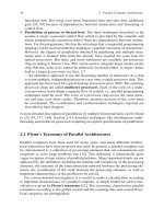
Many graphics processing units (GPUs) also exhibit a hierarchical design. An exam-
ple is shown in Fig. 2.8 for the Nvidia GeForce 8800, which has 128 stream proces-
sors (SP) at 1.35 GHz organized in 8 texture/processor clusters (TPC) such that each
TPC contains 16 SPs. This architecture is scalable to smaller and larger configura-
tions by scaling the number of SPs and memory partitions, see [137] for a detailed
description.
CacheCache
Cache Cache
cache/memory
cache/memory
memory
memory
memory
memory
control
interconnection network
core core corecore
core
core
core
core
pipelined designhierarchical design network-based design
cachecache
corecore
core
core
Fig. 2.6 Design choices for multicore chips according to [107]
This
figure
will be
printed
in b/w
2.4 Thread-Level Parallelism 25
Core 2 Core 3 Core 4
L1 L1 L1 L1
L2 L2 L2 L2
Core 1
L3 Cache (shared)
crossbar
Hyper-Transport memory controller
L1
Core 1
L2Cache (shared)
Core 2
L1
Core 3
L1
L2Cache (shared)
Core 4
L1
Front-Side Bus Front-Side Bus
memory controller
(a)
(b)
Fig. 2.7 Quad-Core AMD Opteron (left) vs. Intel Quad-Core Xeon architecture (right)asexam-
ples for a hierarchical design
This
figure
will be
printed
in b/w
Host
Input Assembler
Vtx Thread Issue
Geom Thread Issue
Setup / Rstr / ZCull
Pixel Thread Issue
Memory
Thread Processor
L2L2L2L2
2L2L
SPSP
TF
L1
SPSP
TF
L1
SPSP
TF
L1
SPSP
TF
L1
SPSP
TF
L1
SPSP
TF
L1
SPSP
TF
L1
SPSP
TF
L1
Fig. 2.8 Architectural overview of Nvidia GeForce 8800, see [128, 137] for a detailed description
This
figure
will be
printed
in b/w
2.4.3.2 Pipelined Designs
For a pipelined design, data elements are processed by multiple execution cores in
a pipelined way. Data elements enter the processor chip via an input port and are
passed successively through different cores until the processed data elements leave
the last core and the entire processor chip via an output port, see Fig. 2.6 (middle).
Each core performs specific processing steps on each data element.
Pipelined designs are useful for application areas in which the same computation
steps have to be applied to a long sequence of data elements. Network processors
used in routers and graphics processors both perform this style of computations.
Examples for network processors with a pipelined design are the Xelerator X10 and
X11 processors [176, 107] for the successive processing of network packets in a
pipelined way within the chip. The Xelerator X11 contains up to 800 separate cores
which are arranged in a logically linear pipeline, see Fig. 2.9 for an illustration. The
network packets to be processed enter the chip via multiple input ports on one side
of the chip, are successively processed by the cores, and then exit the chip.
26 2 Parallel Computer Architecture
Receive Module
Look Aside
Engine
Look Aside
Engine 0
Look Aside
Engine 1
Look Aside
Engine 2 Engine 3
Look Aside
Engine
Hash
Engine
Meter
Engine
Counter
Engine
TCAM
RX,
MAC
RX,
MAC
RX,
MAC
RX,
MAC
XAUI or 12x
Serdes−SGMII
XAUI or 12x
Serdes−SGMII
Arbiter
Port
X
AUI or SPI4.2
XAUI or SPI4.2
Multicast
Copier
TX,
MAC
TX,
MAC
TX,
MAC
TX,
MAC
XAUI or 12x
Serdes−SGMII
XAUI or 12x
Serdes−SGMII
CPU i/f
Control CPU
Optional TCAM Optional RLDRAM, FCRAM, SRAM or LAI co-processor
XAUI or SPI4.2
XAUI or SPI4.2
Transmit Module
Priority Buffer Manager
PISC
Block
#0
PISC
Block
#1
PISC
Block
#2
PISC
Block
#3
PISC
Block
#4
Programmable Pipeline
Processor 2
Processor 31
Look−back path
Processor 0
Processor 1
A
P
E
A
P
E
A
P
E
A
P
E
A
P
E
Fig. 2.9 Xelerator X11 network processor as an example for a pipelined design [176]
2.4.3.3 Network-Based Design
For a network-based design, the cores of a processor chip and their local caches and
memories are connected via an interconnection network with other cores of the chip,
see Fig. 2.6 (right) for an illustration. Data transfer between the cores is performed
via the interconnection network. This network may also provide support for the
synchronization of the cores. Off-chip interfaces may be provided via specialized
cores or DMA ports. An example for a network-based design is the Intel Teraflop
processor, which has been designed by the Intel Tera-scale Computing Research
Program [83, 17].
This research program addresses the challenges of building processor chips with
tens to hundreds of execution cores, including core design, energy management,
cache and memory hierarchy, and I/O. The Teraflop processor developed as a pro-
totype contains 80 cores, which are arranged in a 8×10 mesh, see Fig. 2.10 for an
illustration. Each core can perform floating-point operations and contains a local
cache as well as a router to perform data transfer between the cores and the main
memory. There are additional cores for processing video data, encryption, and
graphics computations. Depending on the application area, the number of special-
ized cores of such a processor chip could be varied.
2.4.3.4 Future Trends and Developments
The potential of multicore processors has been realized by most processor man-
ufacturers like Intel or AMD, and since about 2005, many manufacturers deliver
processors with two or more cores. Since 2007, Intel and AMD provide quad-core
processors (like the Quad-Core AMD Opteron and the Quad-Core Intel Xeon), and
2.4 Thread-Level Parallelism 27
HD
CY
DSP
GFX
GFX
GFX
HD
CY
DSP
GFX
DSP
Graphics
Crypto
HD Video
Cache
Shared
Cache
Local
Streamlined
IA Core
Fig. 2.10 Intel Teraflop processor according to [83] as an example for a network-based design of
a multicore processor
This
figure
will be
printed
in b/w
the provision of oct-core processors is expected in 2010. The IBM Cell processor
integrates one standard desktop core based on the Power Architecture and eight
specialized processing cores. The UltraSPARC T2 processor from Sun has up to
eight processing cores each of which can simulate eight threads using SMT (which
is called CoolThreads by Sun). Thus, an UltraSPARC T2 processor can simultane-
ously execute up to 64 threads.
An important issue for the integration of a large number of cores in one processor
chip is an efficient on-chip interconnection, which provides enough bandwidth for
data transfers between the cores [83]. This interconnection should be scalable to
support an increasing number of cores for future generations of processor designs
and robust to tolerate failures of specific cores. If one or a few cores exhibit hard-
ware failures, the rest of the cores should be able to continue operation. The inter-
connection should also support an efficient energy management which allows the
scale-down of power consumption of individual cores by reducing the clock speed.
For an efficient use of processing cores, it is also important that the data to be
processed be transferred to the cores fast enough to avoid the cores to wait for
the data to be available. Therefore, an efficient memory system and I/O system
are important. The memory system may use private first-level (L1) caches which
can only be accessed by their associated cores, as well as shared second-level (L2)
caches which can contain data of different cores. In addition, a shared third-level
(L3) cache is often used. Processor chip with dozens or hundreds of cores will likely
require an additional level of caches in the memory hierarchy to fulfill bandwidth
requirements [83]. The I/O system must be able to provide enough bandwidth to
keep all cores busy for typical application programs. At the physical layer, the I/O
system must be able to bring hundreds of gigabits per second onto the chip. Such
powerful I/O systems are currently under development [83].
Table 2.1 gives a short overview of typical multicore processors in 2009. For
a more detailed treatment of the architecture of multicore processors and further
examples, we refer to [137, 84].
28 2 Parallel Computer Architecture
Table 2.1 Examples for multicore processors in 2009
Number of Number of Clock L1 L2 L3 Year
Processor cores threads GHz cache cache cache released
Intel Xeon E5450 4 4 3.0 4× 2× 2007
“Harpertown” 32 KB 6.1 MB
Intel Xeon E5540 4 8 2.53 4× 4× 8 MB 2009
“Gainestown” 64 KB 256 MB
AMD Opteron 4 4 2.0 4× 4× 2 MB 2007
“Barcelona” 64 KB 512 KB
AMD Opteron 6 6 2.8 6× 6× 6 MB 2009
“Istanbul” 128 KB 512 KB
IBM 244.7128KB2× 32 MB 2007
Power6 4 MB
Sun T2 8 64 1.17 8× 4 MB 2007
Niagara 2 8 KB
2.5 Interconnection Networks
A physical connection between the different components of a parallel system is
provided by an interconnection network. Similar to control flow and data flow,
see Sect. 2.2, or memory organization, see Sect. 2.3, the interconnection network
can also be used for a classification of parallel systems. Internally, the network
consists of links and switches which are arranged and connected in some regular
way. In multicomputer systems, the interconnection network is used to connect
the processors or nodes with each other. Interactions between the processors for
coordination, synchronization, or exchange of data are obtained by communication
through message-passing over the links of the interconnection network. In multipro-
cessor systems, the interconnection network is used to connect the processors with
the memory modules. Thus, memory accesses of the processors are performed via
the interconnection network.
In both cases, the main task of the interconnection network is to transfer a mes-
sage from a specific processor to a specific destination. The message may contain
data or a memory request. The destination may be another processor or a memory
module. The requirement for the interconnection network is to perform the message
transfer correctly as fast as possible, even if several messages have to be transferred
at the same time. Message transfer and memory accesses represent a significant part
of operations of parallel systems with a distributed or shared address space. There-
fore, the interconnection network used represents a significant part of the design of a
parallel system and may have a large influence on its performance. Important design
criteria of networks are
• the topology describing the interconnection structure used to connect different
processors or processors and memory modules and
• the routing technique describing the exact message transmission used within the
network between processors or processors and memory modules.
2.5 Interconnection Networks 29
The topology of an interconnection network describes the geometric structure
used for the arrangement of switches and links to connect processors or processors
and memory modules. The geometric structure can be described as a graph in which
switches, processors, or memory modules are represented as vertices and physical
links are represented as edges. It can be distinguished between static and dynamic
interconnection networks. Static interconnection networks connect nodes (proces-
sors or memory modules) directly with each other by fixed physical links. They are
also called direct networks or point-to-point networks. The number of connec-
tions to or from a node may vary from only one in a star network to the total number
of nodes in the network for a completely connected graph, see Sect. 2.5.2. Static
networks are often used for systems with a distributed address space where a node
comprises a processor and the corresponding memory module. Dynamic intercon-
nection networks connect nodes indirectly via switches and links. They are also
called indirect networks. Examples of indirect networks are bus-based networks
or switching networks which consist of switches connected by links. Dynamic net-
works are used for both parallel systems with distributed and shared address space.
Often, hybrid strategies are used [35].
The routing technique determines how and along which path messages are trans-
ferred in the network from a sender to a receiver. A path in the network is a series
of nodes along which the message is transferred. Important aspects of the routing
technique are the routing algorithm which determines the path to be used for the
transmission and the switching strategy which determines whether and how mes-
sages are cut into pieces, how a routing path is assigned to a message, and how a
message is forwarded along the processors or switches on the routing path.
The combination of routing algorithm, switching strategy, and network topology
determines the performance of a network significantly. In Sects. 2.5.2 and 2.5.4,
important direct and indirect networks are described in more detail. Specific routing
algorithms and switching strategies are presented in Sects. 2.6.1 and 2.6.3. Efficient
algorithms for the realization of common communication operations on different
static networks are given in Chap. 4. A more detailed treatment of interconnection
networks is given in [19, 35, 44, 75, 95, 115, 158].
2.5.1 Properties of Interconnection Networks
Static interconnection networks use fixed links between the nodes. They can be
described by a connection graph G = (V, E) where V is a set of nodes to be con-
nected and E is a set of direct connection links between the nodes. If there is a direct
physical connection in the network between the nodes u ∈ V and v ∈ V , then it is
(u,v) ∈E. For most parallel systems, the interconnection network is bidirectional.
This means that along a physical link messages can be transferred in both directions
at the same time. Therefore, the connection graph is usually defined as an undirected
graph. When a message must be transmitted from a node u to a node v and there
is no direct connection between u and v in the network, a path from u to v must
be selected which consists of several intermediate nodes along which the message