Parallel Programming: for Multicore and Cluster Systems- P8 pot
Bạn đang xem bản rút gọn của tài liệu. Xem và tải ngay bản đầy đủ của tài liệu tại đây (210.05 KB, 10 trang )
60 2 Parallel Computer Architecture
is received by each switch on the path (store) before it is sent to the next switch
on the path (forward). The connection between two switches A and B on the path
is released for reuse by another packet as soon as the packet has been stored at B.
This strategy is useful if the links connecting the switches on a path have different
bandwidths as this is typically the case in wide area networks (WANs). In this case,
store-and-forward routing allows the utilization of the full bandwidth for every link
on the path. Another advantage is that a link on the path can be quickly released
as soon as the packet has passed the links, thus reducing the danger of deadlocks.
The drawback of this strategy is that the packet transmission time increases with the
number of switches that must be traversed from source to destination. Moreover, the
entire packet must be stored at each switch on the path, thus increasing the memory
demands of the switches.
The time for sending a packet of size m over a single link takes time t
h
+ t
B
· m
where t
h
is the constant time needed at each switch to store the packet in a receive
buffer and to select the output channel to be used by inspecting the header informa-
tion of the packet. Thus, for a path of length l, the entire time for packet transmission
with store-and-forward routing is
T
sf
(m, l) = t
S
+l(t
h
+t
B
·m). (2.5)
Since t
h
is typically small compared to the other terms, this can be reduced to
T
sf
(m, l) ≈ t
S
+ l · t
B
· m. Thus, the time for packet transmission depends lin-
early on the packet size and the length l of the path. Packet transmission with store-
and-forward routing is illustrated in Fig. 2.30(b). The time for the transmission of
an entire message, consisting of several packets, depends on the specific routing
algorithm used. When using a deterministic routing algorithm, the message trans-
mission time is the sum of the transmission time of all packets of the message, if
no network delays occur. For adaptive routing algorithms, the transmission of the
individual packets can be overlapped, thus potentially leading to a smaller message
transmission time.
If all packets of a message are transmitted along the same path, pipelining can
be used to reduce the transmission time of messages: Using pipelining, the packets
of a message are sent along a path such that the links on the path are used by suc-
cessive packets in an overlapping way. Using pipelining for a message of size m and
packet size m
p
, the time of message transmission along a path of length l can be
described by
t
S
+(m −m
p
)t
B
+l(t
h
+t
B
·m
p
) ≈ t
S
+m ·t
B
+(l − 1)t
B
·m
p
, (2.6)
where l(t
h
+ t
B
· m
p
) is the time that elapses before the first packet arrives at the
destination node. After this time, a new packet arrives at the destination in each time
step of size m
p
·t
B
, assuming the same bandwidth for each link on the path.
2.6 Routing and Switching 61
H
H
H
H
H
0
1
2
3
H
H
H
store−and−forward
0
1
2
3
0
1
2
3
cut−through
(a)
(b)
(c)
source
destination
node
node
node
source
source
destination
destination
time (activity at the node)
time (activity at the node)
(activity at the node)time
packet switching with
packet switching with
path
construction
entire path is active during
entire message transmission
transmission
over the first
link
header
transmission
packet
transmission
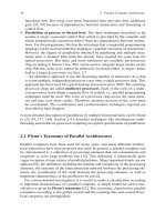
Fig. 2.30 Illustration of the latency of a point-to-point transmission along a path of length l = 4
for (a) circuit switching, (b) packet switching with store and forward, and (c) packet switching
with cut-through
2.6.3.4 Cut-Through Routing
The idea of the pipelining of message packets can be extended by applying pipelin-
ing to the individual packets. This approach is taken by cut-through routing.Using
this approach, a message is again split into packets as required by the packet-
switching approach. The different packets of a message can take different paths
through the network to reach the destination. Each individual packet is sent through
the network in a pipelined way. To do so, each switch on the path inspects the first
62 2 Parallel Computer Architecture
few phits (physical units) of the packet header, containing the routing information,
and then determines over which output channel the packet is forwarded. Thus, the
transmission path of a packet is established by the packet header and the rest of the
packet is transmitted along this path in a pipelined way. A link on this path can be
released as soon as all phits of the packet, including a possible trailer, have been
transmitted over this link.
The time for transmitting a header of size m
H
along a single link is given by
t
H
= t
B
· m
H
. The time for transmitting the header along a path of length l is then
given by t
H
· l. After the header has arrived at the destination node, the additional
time for the arrival of the rest of the packet of size m is given by t
B
(m −m
H
). Thus,
the time for transmitting a packet of size m along a path of length l using packet
switching with cut-through routing can be expressed as
T
ct
(m, l) = t
S
+l · t
H
+t
B
·(m −m
H
) . (2.7)
If m
H
is small compared to the packet size m, this can be reduced to T
ct
(m, l) ≈
t
S
+ t
B
· m. If all packets of a message use the same transmission path, and if
packet transmission is also pipelined, this formula can also be used to describe the
transmission time of the entire message. Message transmission time using packet
switching with cut-through routing is illustrated in Fig. 2.30(c).
Until now, we have considered the transmission of a single message or packet
through the network. If multiple transmissions are performed concurrently, net-
work contention may occur because of conflicting requests to the same links. This
increases the communication time observed for the transmission. The switching
strategy must react appropriately if contention happens on one of the links of a trans-
mission path. Using store-and-forward routing, the packet can simply be buffered
until the output channel is free again.
With cut-through routing, two popular options are available: virtual cut-through
routing and wormhole routing.Usingvirtual cut-through routing, in case of a
blocked output channel at a switch, all phits of the packet in transmission are col-
lected in a buffer at the switch until the output channel is free again. If this happens at
every switch on the path, cut-through routing degrades to store-and-forward routing.
Using partial cut-through routing, the transmission of the buffered phits of a packet
can continue as soon as the output channel is free again, i.e., not all phits of a packet
need to be buffered.
The wormhole routing approach is based on the definition of flow control units
(flits) which are usually at least as large as the packet header. The header flit estab-
lishes the path through the network. The rest of the flits of the packet follow in a
pipelined way on the same path. In case of a blocked output channel at a switch,
only a few flits are stored at this switch, the rest is kept on the preceding switches
of the path. Therefore, a blocked packet may occupy buffer space along an entire
path or at least a part of the path. Thus, this approach has some similarities to circuit
switching at packet level. Storing the flits of a blocked message along the switches
of a path may cause other packets to block, leading to network saturation. More-
over, deadlocks may occur because of cyclic waiting, see Fig. 2.31 [125, 158]. An
2.6 Routing and Switching 63
B
B
B
B
B
B
B
B
B
B
B
B
B
B
B
B
B
flit buffer
resource request
resource assignment
selected forwarding channel
packet 1
packet 3
packet 2
packet 4
Fig. 2.31 Illustration of a deadlock situation with wormhole routing for the transmission of four
packets over four switches. Each of the packets occupies a flit buffer and requests another flit buffer
at the next switch; but this flit buffer is already occupied by another packet. A deadlock occurs,
since none of the packets can be transmitted to the next switch
advantage of the wormhole routing approach is that the buffers at the switches can
be kept small, since they need to store only a small portion of a packet.
Since buffers at the switches can be implemented large enough with today’s tech-
nology, virtual cut-through routing is the more commonly used switching technique
[84]. The danger of deadlocks can be avoided by using suitable routing algorithms
like dimension-ordered routing or by using virtual channels, see Sect. 2.6.1.
2.6.4 Flow Control Mechanisms
A general problem in network may arise form the fact that multiple messages can be
in transmission at the same time and may attempt to use the same network links at
the same time. If this happens, some of the message transmissions must be blocked
while others are allowed to proceed. Techniques to coordinate concurrent message
transmissions in networks are called flow control mechanisms. Such techniques are
important in all kinds of networks, including local and wide area networks, and
popular protocols like TCP contain sophisticated mechanisms for flow control to
obtain a high effective network bandwidth, see [110, 139] for more details. Flow
control is especially important for networks of parallel computers, since these must
be able to transmit a large number of messages fast and reliably. A loss of messages
cannot be tolerated, since this would lead to errors in the parallel program currently
executed.
Flow control mechanisms typically try to avoid congestion in the network to
guarantee fast message transmission. An important aspect is the flow control mech-
anisms at the link level which considers message or packet transmission over a
single link of the network. The link connects two switches A and B. We assume
that a packet should be transmitted from A to B. If the link between A and B is
64 2 Parallel Computer Architecture
free, the packet can be transferred from the output port of A to the input port of
B from which it is forwarded to the suitable output port of B.ButifB is busy,
there might be the situation that B does not have enough buffer space in the input
port available to store the packet from A. In this case, the packet must be retained
in the output buffer of A until there is enough space in the input buffer of B.
But this may cause back pressure to switches preceding A, leading to the danger
of network congestion. The idea of link-level flow control mechanisms is that the
receiving switch provides a feedback to the sending switch, if enough input buffer
space is not available, to prevent the transmission of additional packets. This feed-
back rapidly propagates backward in the network until the original sending node is
reached. The sender can then reduce its transmission rate to avoid further packet
delays.
Link-level flow control can help to reduce congestion, but the feedback prop-
agation might be too slow and the network might already be congested when the
original sender is reached. An end-to-end flow control with a direct feedback to the
original sender may lead to a faster reaction. A windowing mechanism as used by
the TCP protocol is one possibility for implementation. Using this mechanism, the
sender is provided with the available buffer space at the receiver and can adapt the
number of packets sent such that no buffer overflow occurs. More information can
be found in [110, 139, 84, 35].
2.7 Caches and Memory Hierarchy
A significant characteristic of the hardware development during the last decades
has been the increasing gap between processor cycle time and main memory access
time, see Sect. 2.1. The main memory is constructed based on DRAM (dynamic ran-
dom access memory). A typical DRAM chip has a memory access time between 20
and 70 ns whereas a 3 GHz processor, for example, has a cycle time of 0.33 ns, lead-
ing to 60–200 cycles for a main memory access. To use processor cycles efficiently,
a memory hierarchy is typically used, consisting of multiple levels of memories with
different sizes and access times. Only the main memory on the top of the hierarchy is
built from DRAM, the other levels use SRAM (static random access memory), and
the resulting memories are often called caches. SRAM is significantly faster than
DRAM, but has a smaller capacity per unit area and is more costly. When using a
memory hierarchy, a data item can be loaded from the fastest memory in which it is
stored. The goal in the design of a memory hierarchy is to be able to access a large
percentage of the data from a fast memory, and only a small fraction of the data
from the slow main memory, thus leading to a small average memory access time.
The simplest form of a memory hierarchy is the use of a single cache between
the processor and main memory (one-level cache, L1 cache). The cache contains a
subset of the data stored in the main memory, and a replacement strategy is used
to bring new data from the main memory into the cache, replacing data elements
that are no longer accessed. The goal is to keep those data elements in the cache
2.7 Caches and Memory Hierarchy 65
which are currently used most. Today, two or three levels of cache are used for each
processor, using a small and fast L1 cache and larger, but slower L2 and L3 caches.
For multiprocessor systems where each processor uses a separate local cache,
there is the additional problem of keeping a consistent view of the shared address
space for all processors. It must be ensured that a processor accessing a data element
always accesses the most recently written data value, also in the case that another
processor has written this value. This is also referred to as cache coherence prob-
lem and will be considered in more detail in Sect. 2.7.3.
For multiprocessors with a shared address space, the top level of the memory
hierarchy is the shared address space that can be accessed by each of the processors.
The design of a memory hierarchy may have a large influence on the execution
time of parallel programs, and memory accesses should be ordered such that a given
memory hierarchy is used as efficiently as possible. Moreover, techniques to keep a
memory hierarchy consistent may also have an important influence. In this section,
we therefore give an overview of memory hierarchy design and discuss issues of
cache coherence and memory consistency. Since caches are the building blocks of
memory hierarchies and have a significant influence on the memory consistency, we
give a short overview of caches in the following subsection. For a more detailed
treatment, we refer to [35, 84, 81, 137].
2.7.1 Characteristics of Caches
A cache is a small, but fast memory between the processor and the main mem-
ory. Caches are built with SRAM. Typical access times are 0.5–2.5 ns (ns =
nanoseconds = 10
−9
seconds) compared to 50–70 ns for DRAM (values from 2008
[84]). In the following, we consider a one-level cache first. A cache contains a copy
of a subset of the data in main memory. Data is moved in blocks, containing a small
number of words, between the cache and main memory, see Fig. 2.32. These blocks
of data are called cache blocks or cache lines. The size of the cache lines is fixed
for a given architecture and cannot be changed during program execution.
Cache control is decoupled from the processor and is performed by a sepa-
rate cache controller. During program execution, the processor specifies memory
addresses to be read or to be written as given by the load and store operations
of the machine program. The processor forwards the memory addresses to the
memory system and waits until the corresponding values are returned or written.
The processor specifies memory addresses independently of the organization of the
processor
main
memory
word block
cache
Fig. 2.32 Data transport between cache and main memory is done by the transfer of memory
blocks comprising several words whereas the processor accesses single words in the cache
66 2 Parallel Computer Architecture
memory system, i.e., the processor does not need to know the architecture of the
memory system. After having received a memory access request from the proces-
sor, the cache controller checks whether the memory address specified belongs to
a cache line which is currently stored in the cache. If this is the case, a cache hit
occurs, and the requested word is delivered to the processor from the cache. If the
corresponding cache line is not stored in the cache, a cache miss occurs, and the
cache line is first copied from main memory into the cache before the requested
word is delivered to the processor. The corresponding delay time is also called
miss penalty. Since the access time to main memory is significantly larger than
the access time to the cache, a cache miss leads to a delay of operand delivery to the
processor. Therefore, it is desirable to reduce the number of cache misses as much as
possible.
The exact behavior of the cache controller is hidden from the processor. The
processor observes that some memory accesses take longer than others, leading to
a delay in operand delivery. During such a delay, the processor can perform other
operations that are independent of the delayed operand. This is possible, since the
processor is not directly occupied for the operand access from the memory system.
Techniques like operand prefetch can be used to support an anticipated loading of
operands so that other independent operations can be executed, see [84].
The number of cache misses may have a significant influence on the result-
ing runtime of a program. If many memory accesses lead to cache misses, the
processor may often have to wait for operands, and program execution may be
quite slow. Since cache management is implemented in hardware, the program-
mer cannot directly specify which data should reside in the cache at which point
in program execution. But the order of memory accesses in a program can have a
large influence on the resulting runtime, and a reordering of the memory accesses
may lead to a significant reduction of program execution time. In this context,
the locality of memory accesses is often used as a characterization of the mem-
ory accesses of a program. Spatial and temporal locality can be distinguished as
follows:
• The memory accesses of a program have a high spatial locality, if the program
often accesses memory locations with neighboring addresses at successive points
in time during program execution. Thus, for programs with high spatial locality
there is often the situation that after an access to a memory location, one or more
memory locations of the same cache line are also accessed shortly afterward.
In such situations, after loading a cache block, several of the following memory
locations can be loaded from this cache block, thus avoiding expensive cache
misses. The use of cache blocks comprising several memory words is based on
the assumption that most programs exhibit spatial locality, i.e., when loading
a cache block not only one but several memory words of the cache block are
accessed before the cache block is replaced again.
• The memory accesses of a program have a high temporal locality,ifitoften
happens that the same memory location is accessed multiple times at successive
points in time during program execution. Thus, for programs with a high temporal
2.7 Caches and Memory Hierarchy 67
locality there is often the situation that after loading a cache block in the cache,
the memory words of the cache block are accessed multiple times before the
cache block is replaced again.
For programs with small spatial locality there is often the situation that after
loading a cache block, only one of the memory words contained is accessed before
the cache block is replaced again by another cache block. For programs with small
temporal locality, there is often the situation that after loading a cache block because
of a memory access, the corresponding memory location is accessed only once
before the cache block is replaced again. Many program transformations to increase
temporal or spatial locality of programs have been proposed, see [12, 175] for more
details.
In the following, we give a short overview of important characteristics of caches.
In particular, we consider cache size, mapping of memory blocks to cache blocks,
replacement algorithms, and write-back policies. We also consider the use of multi-
level caches.
2.7.1.1 Cache Size
Using the same hardware technology, the access time of a cache increases (slightly)
with the size of the cache because of an increased complexity of the addressing. But
using a larger cache leads to a smaller number of replacements as a smaller cache,
since more cache blocks can be kept in the cache. The size of the caches is limited by
the available chip area. Off-chip caches are rarely used to avoid the additional time
penalty of off-chip accesses. Typical sizes for L1 caches lie between 8K and 128K
memory words where a memory word is four or eight bytes long, depending on the
architecture. During the last years, the typical size of L1 caches has not increased
significantly.
If a cache miss occurs when accessing a memory location, an entire cache block
is brought into the cache. For designing a memory hierarchy, the following points
have to be taken into consideration when fixing the size of the cache blocks:
• Using larger blocks reduces the number of blocks that fit in the cache when using
the same cache size. Therefore, cache blocks tend to be replaced earlier when
using larger blocks compared to smaller blocks. This suggests to set the cache
block size as small as possible.
• On the other hand, it is useful to use blocks with more than one memory word,
since the transfer of a block with x memory words from main memory into the
cache takes less time than x transfers of a single memory word. This suggests to
use larger cache blocks.
As a compromise, a medium block size is used. Typical sizes for L1 cache blocks
are four or eight memory words.
68 2 Parallel Computer Architecture
2.7.1.2 Mapping of Memory Blocks to Cache Blocks
Data is transferred between main memory and cache in blocks of a fixed length.
Because the cache is significantly smaller than the main memory, not all memory
blocks can be stored in the cache at the same time. Therefore, a mapping algo-
rithm must be used to define at which position in the cache a memory block can be
stored. The mapping algorithm used has a significant influence on the cache behav-
ior and determines how a stored block is localized and retrieved from the cache.
For the mapping, the notion of associativity plays an important role. Associativity
determines at how many positions in the cache a memory block can be stored. The
following methods are distinguished:
• for a direct mapped cache, each memory block can be stored at exactly one
position in the cache;
• for a fully associative cache, each memory block can be stored at an arbitrary
position in the cache;
• for a set associative cache, each memory block can be stored at a fixed number
of positions.
In the following, we consider these three mapping methods in more detail for a
memory system which consists of a main memory and a cache. We assume that the
main memory comprises n = 2
s
blocks which we denote as B
j
for j = 0, ,n−1.
Furthermore, we assume that there are m = 2
r
cache positions available; we denote
the corresponding cache blocks as
¯
B
i
for i = 0, ,m −1. The memory blocks and
the cache blocks have the same size of l = 2
w
memory words. At different points of
program execution, a cache block may contain different memory blocks. Therefore,
for each cache block a tag must be stored, which identifies the memory block that
is currently stored. The use of this tag information depends on the specific mapping
algorithm and will be described in the following. As running example, we consider a
memory system with a cache of size 64 Kbytes which uses cache blocks of 4 bytes.
Thus, 16K = 2
14
blocks of four bytes each fit into the cache. With the notation from
above, it is r = 14 and w = 2. The main memory is 4 Gbytes = 2
32
bytes large,
i.e., it is s = 30 if we assume that a memory word is one byte. We now consider the
three mapping methods in turn.
2.7.1.3 Direct Mapped Caches
The simplest form to map memory blocks to cache blocks is implemented by direct
mapped caches. Each memory block B
j
can be stored at only one specific cache
location. The mapping of a memory block B
j
to a cache block
¯
B
i
is defined as
follows:
B
j
is mapped to
¯
B
i
if i = j mod m.
Thus, there are n/m = 2
s−r
different memory blocks that can be stored in one
specific cache block
¯
B
i
. Based on the mapping, memory blocks are assigned to
cache positions as follows:
2.7 Caches and Memory Hierarchy 69
cache block memory block
00, m, 2m, ,2
s
−m
11, m +1, 2m +1, ,2
s
−m +1
.
.
.
.
.
.
m −1 m −1, 2m −1, 3m − 1, ,2
s
−1
Since the cache size m is a power of 2, the modulo operation specified by the
mapping function can be computed by using low-order bits of the memory address
specified by the processor. Since a cache block contains l = 2
w
memory words, the
memory address can be partitioned into a word address and a block address. The
block address specifies the position of the corresponding memory block in main
memory. It consists of the s most significant (leftmost) bits of the memory address.
The word address specifies the position of the memory location in the memory
block, relative to the first location of the memory block. It consists of the w least
significant (rightmost) bits of the memory address.
For a direct mapped cache, the r rightmost bits of the block address of a memory
location define at which of the m = 2
r
cache positions the corresponding memory
block must be stored if the block is loaded into the cache. The remaining s − r
bits can be interpreted as tag which specifies which of the 2
s−r
possible memory
blocks is currently stored at a specific cache position. This tag must be stored with
the cache block. Thus each memory address is partitioned as follows:
tag
s − r r w
cache position
block address word address
For the running example, the tags consist of s −r = 16 bits for a direct mapped
cache.
Memory access is illustrated in Fig. 2.33(a) for an example memory system with
block size 2 (w = 1), cache size 4 (r = 2), and main memory size 16 (s = 4).
For each memory access specified by the processor, the cache position at which the
requested memory block must be stored is identified by considering the r rightmost
bits of the block address. Then the tag stored for this cache position is compared
with the s − r leftmost bits of the block address. If both tags are identical, the
referenced memory block is currently stored in the cache, and memory access can
be done via the cache. A cache hit occurs. If the two tags are different, the requested
memory block must first be loaded into the cache at the given cache position before
the memory location specified can be accessed.
Direct mapped caches can be implemented in hardware without great effort, but
they have the disadvantage that each memory block can be stored at only one cache
position. Thus, it can happen that a program repeatedly specifies memory addresses
in different memory blocks that are mapped to the same cache position. In this
situation, the memory blocks will be continually loaded and replaced in the cache,