The Complete IS-IS Routing Protocol- P15 ppsx
Bạn đang xem bản rút gọn của tài liệu. Xem và tải ngay bản đầy đủ của tài liệu tại đây (150.82 KB, 10 trang )
Router A
Router B
circuit #1
circuit #2
I have an adjacency with
Router B on circuit #1
I have an adjacency with
Router A on circuit #2
1
Tx
Rx
Tx
Rx
Rx
Tx
Rx
Tx
2
3
4
5
F
IGURE
5.12. Two reported unidirectional LSP advertisements make other routers think that there is a single bi-directional adv
ertisement
127
5.3.3 The 3-way Handshake on Point-to-point Circuits
In LAN environments, the IS Neighbour TLV #6 does convey the information elements
needed for performing the 3-way handshaking function. Unfortunately, this specific TLV
is tailored to LAN environments only. Recall that the information elements to transport
the “Hello, I have seen you” message is the SNPA,a MAC address. MAC addresses are
typical to broadcast circuits such as, Ethernet, however, the typical WAN OSI-RM Layer 2
protocols like PPP, Cisco-HDLC, Frame-Relay, or ATM RFC 1483-SNAP, do not have
the notion of MAC addresses. All of those WAN protocols are optimized for point-to-
point environments where MAC addressing is not used or necessary. Typically the WAN
protocols just need to frame a packet and transmit it to the remote end. Addressing is not
needed because there are just two speakers on the circuit: the remote router and the local
router. Fortunately, there is an extension to the base ISO 10589 specification, RFC 3373,
that specifies an optional TLV that carries adjacency states and a few other information
elements in a special TLV. The Adjacency State TLV #240 is discussed in the next section.
5.3.3.1 Adjacency State TLV #240
The main purpose of transporting adjacency states is to find out if the Hello message that
a router has received was sent in response to receipt of a previous Hello, or is just any
Hello sent by the remote router. If a router detects that the Hello received was sent in
response to a previous Hello message sent, it is safe to assume the routers are on a work-
ing, bi-directional circuit. This excludes the set of problems previously discussed that
resulted from the presence of unidirectional circuits.
Figure 5.13 shows the structure of the Adjacency State TLV #240 TLV. The TLV is a
variable length and can span 1, 5, 11 or 15 bytes. The minimum length is 1 byte. The first
byte conveys the current state of the adjacency, which can be one of three values:
•
0x2 Down
•
0x1 Initializing
•
0x0 Up
128 5. Neighbour Discovery and Handshaking
TLV Type
TLV Length
Adjacency State
240
Bytes
1
1
1
1, 5, 11, 15
Extended Local Circuit-ID 4
Neighbour System-ID 6
Neighbour Extended Local Circuit-ID 4
Optional
FIGURE 5.13. The second part of the Adjacency State TLV is optional
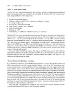
Figure 5.14 shows how the TLV content is changed during a 3-way handshake. Here
is how the TLV works in the 3-way handshake:
1. Router A send a Hello reporting the adjacency as Down
2. Router B replies to Router A’s Hello. Router B tells Router A that this particular Hello
message was generated in response to Router A’s previous Hello message by setting
the Adjacency State to Initializing. Router A now knows that the circuit is truly
bi-directional and declares the adjacency Up.
3. Router A sends a Hello back to Router B setting the Adjacency State to Up which
causes Router B to declare the adjacency up on the Router B side as well.
There are two different flavours of the Adjacency TLV deployed in the field. The
first one is derived from one of the first Internet drafts before the document was extended
and finally went to RFC state. The early version is a crippled version which just carries
a single byte adjacency state. The more recent flavour implements the full 15 bytes
of RFC 3373. From the router’s debug logs and show commands you cannot tell
if you receive the single or 15-byte version. Tcpdump is used to reveal the version
received.
Handshaking 129
tt
Router A Router B
Router B
Adjacency UP
IS-IS enabled
on the circuit
Router A
Adjacency UP
IIH
Router B
Adj. State TLV #240
“Initializing”
IIH
Router A
Adj. State TLV #240
“Down”
IIH
Router A
Adj. State TLV #240
“Up”
FIGURE 5.14. JUNOS always sends the 15-byte version of TLV #240, IOS per default sends the
1-byte version and optionally the 15-byte version
Tcpdump output
Older versions of JUNOS and IOS only support the 1-byte Adjacency state TLV #240:
00:29:47.706711 OSI, IS-IS, length: 38
p2p IIH, hlen: 20, v: 1, pdu-v: 1, sys-id-len: 6 (0), max-area: 3(0)
source-id: 1921.6809.0034, holding time: 27s, Flags: [Level 2 only]
circuit-id: 0x01, PDU length: 38
Point-to-point Adjacency State TLV #240, length: 1
Adjacency State: Up
Protocols supported TLV #129, length: 1
NLPID(s): IPv4
IPv4 Interface address(es) TLV #132, length: 4
IPv4 interface address: 172.16.5.156
Area address(es) TLV #1, length: 4
Area address (length: 3): 49.0001
Tcpdump output
Recent versions of JUNOS and IOS support the fully fledged, 15-byte version of the
Adjacency State TLV #240:
11:35:23.248504 OSI, IS-IS, length: 50
p2p IIH, hlen: 20, v: 1, pdu-v: 1, sys-id-len: 6 (0), max-area: 3 (0)
source-id: 1921.6809.0034, holding time: 27s, Flags: [Level 2 only]
circuit-id: 0x01, PDU length: 50
Point-to-point Adjacency State TLV #240, length: 15
Adjacency State: Up
Extended Local circuit ID: 0x0000001a
Neighbor SystemID: 2092.1113.4007
Neighbor Extended Local circuit ID: 0x0000005f
Protocols supported TLV #129, length: 1
NLPID(s): IPv4
IPv4 Interface address(es) TLV #132, length: 4
IPv4 interface address: 172.16.5.156
Area address(es) TLV #1, length: 4
Area address (length: 3): 49.0001
Wrapping just the Adjacency State (1 byte) inside the TLV and not adding the optional 14
bytes information only addresses the unidirectional link problem to some degree. One issue
is still open: A router can never be 100% sure if a change in the adjacency state is targeted
to the receiver itself. A broken or flapping (rapidly up and down) link in a SONET/SDH
environment, which frequently terminates at two different routers, can make IS-IS blind
spotted and causes the same problems that have been observed with the plain 2-way checks.
This issue might seem very far-fetched or esoteric. But the IETF is known for deliver-
ing pragmatic protocols that solve real problems. The fact that the Adjacency State TLV
was revised in a later version of the draft that finally went into RFC 3373 to include the
Neighbours System-ID so that the neighbour can be sure that a change of adjacency state
130 5. Neighbour Discovery and Handshaking
was generated by receipt of the neighbour’s recent Hello message indicates that this was
a real concern. If there was a state change by a neighbour and the Source-ID is not listed
in the Neighbor Extended Local Circuit-ID field, then it was certainly not the receipt of
the router’s Hello change that triggered the state change.
Additionally, there was concern about the size (8 bits) of the Local Circuit-ID field in
the point-to-point Hello message. Modern routers can be configured with literally thou-
sands of interfaces (usually logical interfaces, but still interfaces) and so that field needed
to be extended. TLV #240 transports 32-bit Local Circuit IDs, which should give any
router plenty of Circuit-IDs for the time being. Normally routers insert the local interface
index or SNMP index into this field.
Contemporary JUNOS releases support the 15-byte version of TLV #240 only. In IOS
you can control the emission of the 1-byte or 15-byte version using the isis three-
way-handshake interface configuration option.
IOS configuration
The ietf option to the isis three-way-handshake configuration command emits the
15-byte version of TLV #240. The default parameter is the cisco option which generates
the one-byte TLV payload.
interface POS4/1
[… ]
isis three-way-handshake ietf
encapsulation ppp
[… ]
!
If an implementation follows ISO 10589 by the letter, then the expectation would be
that after a completed 2-way or 3-way check, an adjacency goes into the Up state.
However, this may not be the case. Most implementations perform additional checks
before an adjacency is declared Up.
5.4 Sub-net Checking
IS-IS is often expected to be a true multi-protocol IGP. Because adjacency formation,
database synchronization and topology calculation (through SPF) is based on Layer-2
information, one would expect that it is entirely decoupled from any network layer
dependencies. That assumption does not match the deployed reality. IS-IS routers indeed
do verify that the next-hop the router is announcing is valid. The receiving router checks
all occurrences of the Interface Address TLV #132 and also checks it against the list of
local IP addresses configured on that circuit. Figure 5.15 shows the structure of the IP
Interface Address TLV #132 which is a simple list of IP addresses that contains a router’s
primary and secondary IP addresses.
Both IOS and JUNOS verify that there is a common IP sub-net. If there is no common
IP sub-net there is also no viable next-hop that can be entered in a routing table, and
therefore the adjacency is considered invalid and stays in the Down / Initializing state.
Sub-net Checking 131
There is unfortunately no show command in the router CLI that reports a sub-net mis-
match. You need to turn on debugging in IOS and tracing in JUNOS to get any indication
there is something wrong in this regard.
In IOS, a sub-net mismatch can be detected once the isis adj-packets debug is
turned on. In JUNOS, the trace option flag list needs to include the error flag.
IOS debug output
For IOS to detect sub-net mismatches the debug isis adj-packets needs to be turned
on. Additionally you need to run terminal monitor to display the logging output on the
vty.
London#debug isis adj-packets
IS-IS Adjacency related packets debugging is on
London#terminal monitor
Oct 26 22:33:11: ISIS-Adj: Sending serial IIH on POS4/1, length 4469
Oct 26 22:33:19: ISIS-Adj: Rec serial IIH from *PPP* (POS4/0),
cir type L1L2, cir id 01, length 1492
Oct 26 22:33:19: ISIS-Adj: No usable IP interface addresses in serial IIH
from POS4/0
JUNOS debug output
For JUNOS to detect sub-net mismatches the flag error under the proto-cols isis
traceoptions {} stanza needs to be configured. The logging messages will then be
written into the specified IS-IS logfile (isis.log)
hannes@Frankfurt> show log isis.log
Oct 26 22:16:13 trace_on: Tracing to “/var/log/isis.log” started
[… ]
Oct 26 22:33:43 ISIS L3 periodic xmit to interface so-0/2/2.0
Oct 26 22:33:45 ISIS L3 hello from 1921.6800.1068 interface so-0/2/2.0
absorbed
Oct 26 22:33:45 ISIS ERROR: IIH from 1921.6800.1068 without matching
address, interface so-0/2/2.0
132 5. Neighbour Discovery and Handshaking
TLV Type
TLV Length
IP Address
132
Bytes
1
1
4
4
N * 4
IP Address
FIGURE 5.15. The contents of the Interface Address TLV #132 are matched against the local IP
address to check if there is a matching sub-net
After the sub-net check is positive, and there are no other configuration mismatches,
such as misaligned authentication strings or circuit types and levels, the adjacency
should go to the Up state.
The transition from Down to Up does not occur immediately after receipt of a valid IIH
message. There are some intermediate states in between, and there is also some damping
logic involved, which makes sure that the network is not overwhelmed because of a
flappy link. The next section is about the adjacency finite state machine and hold down
logic of adjacencies.
5.5 Finite State Machine
Most routing protocols maintain a finite state machine (FSM) for neighbour manage-
ment. The FSM is a graph that describes steady states and the events that enable transi-
tions from one state to another. In Figure 5.16 there is a FSM for a 2-way handshake.
The three states are:
•
Down
•
New
•
Up
A receipt of a valid (level, area and authentication needs to match) IIH transitions from
Down to New and finally to Up. A mismatch of level, area and authentication, or a time-
out of interface down events immediately transitions the adjacency from Up to Down.
Two-way adjacencies and hence 2-way state machines are an anachronism (as demon-
strated by the previous examples) and are deprecated today. Figure 5.17 shows the FSM
for the 3-way handshake.
Finite State Machine 133
Adj. Timeout
Intf. Down
bogus System-ID
Area Mismatch
Level Mismatch
rcvd IIH
Adj. Timeout
Intf. Down
bogus System-ID
Area Mismatch
Level Mismatch
rcvd IIH
rcvd IIH
Up
New
Down
FIGURE 5.16. The finite state machine for a 2-way adjacency (deprecated)
The 3-way handshake encompasses four states:
•
Down
•
New
•
Init
•
Up
The additional Init state has been created for 3-way handshake functionality. Upon
receipt of a valid IIH, the adjacency is moved to the Init state. From there a Seenself event
is necessary to proceed to an Up state. The Seenself event can be an Adjacency State of
1 (Init) as part of the Adjacency State TLV #240, or the router’s own SNPA listed in the
IS Neighbour TLV #6.
As soon as an adjacency is declared Up the router needs to originate a LSP packet
reporting the new adjacency to other routers in the network. A good IS-IS implementation
tries to protect other routers from locally flapping adjacencies. That means if the local
circuit is flapping at a high frequency, there is a risk that the entire network will be
overwhelmed with LSPs. Both IOS and JUNOS use timers that artificially hold down
134 5. Neighbour Discovery and Handshaking
Adj. Timeout
Intf. Down
bogus System-ID
Area Mismatch
Level Mismatch
rcvd IIH && seenself
rcvd IIH
rcvd IIH && seenself
rcvd IIH && seenself && hold down timer
Adj. Timeout
Intf. Down
bogus System-ID
Area Mismatch
Level Mismatch
Adj. Timeout
Intf. Down
bogus System-ID
Area Mismatch
Level Mismatch
rcvd IIH
rcvd IIH && seenself
rcvd IIH
Up
Init
Down
New
FIGURE 5.17. The Finite State Machine for a 3-way adjacency
an adjacency that is about to enter the Up state for a limited amount of time. Typically
those timers are in the range of 1–60 seconds depending on factors such as:
•
Flapping history
•
Amount of LSP traffic
•
Number of adjacencies per interface
If an adjacency has flapped frequently in the past then it is highly likely that it will flap
in the future too. It is safe to hold down adjacencies longer if they have a higher amount
of transitions over time. JUNOS does, for example, measure the amount of LSPs that are
transmitted through local interfaces. If the amount of LSPs is higher than one LSP per
second then probably the network is shaky and it is not safe to contribute to further churn
by announcing an additional LSP. Finally, a common action is to treat point-to-point or
single adjacency LAN circuits better than LAN circuits with multiple adjacencies. The
idea behind that is if there are some adjacencies already in the Up state then we are prob-
ably in the middle of taking up a big LAN segment and there will be more changes to
come. Waiting a little extra time here does not do a lot of harm but highly reduces the
churn if a big LAN goes down.
For high-resiliency routing, it is imperative how fast the router detects that an adja-
cency is Down. In the FSM there are two events for Down transitioning: the adjacency
timeout and interface down event. In the next section there is a short overview about
IS-IS neighbour liveliness detection and how that impacts high-resiliency routing.
5.6 Neighbour Liveliness Detection
The Internet has evolved from an academic playground to a business-critical infrastruc-
ture. Customers and their Internet service providers are keen to tune the convergence
speed in case a backup circuit has to be engaged. The most dominant element for con-
vergence behaviour is neighbour liveliness detection. Today there are several options to
detect if a circuit to an adjacent router is still able to deliver packets:
•
IGP Hellos
•
Interface Tracking
•
LMI Protocol
The two major IS-IS implementations treat all three sources of information equally.
5.6.1 IGP Hellos
The historical way of detecting that a neighbour is down is by tracking receipt of a neigh-
bour’s Hello packets. That method has two disadvantages. First, on a busy router with
many adjacencies the generation and receipt of hundreds of IIH messages may over-
whelm the routing process. Second, many routing protocols do not support sub-second
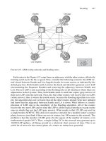
timers. Consider Figure 5.4, which displays a point-to-point IIH header. The Hold Time
field is a discrete 16-bit field which supports timer values from 1–65535 seconds, but no
sub-second timers. The same problem applies to the OSPF routing protocol: The Hello
Neighbour Liveliness Detection 135
136 5. Neighbour Discovery and Handshaking
and Dead timer there needs to be conveyed in the protocol. The lowest unit are once
again seconds. One of the nice things about IS-IS has been that the Hello timer does not
need to get encoded on the Hello message. The Hello timer is a purely local matter. The
timer that gets transported using the IS-IS protocol is the hold timer which can go down
to 1 second. The Hello timer is therefore a fraction of the hold timer.
In IOS and JUNOS sub-second Hello timers are configured differently: IOS needs
the keyword isis hello-interval minimal in its interface configuration.
Depending on the isis-hello-multiplier value, IOS dispatches Hellos in frac-
tions of this value.
IOS configuration
interface POS4/1
[… ]
ip router isis
encapsulation ppp
[… ]
isis hello-multiplier 5 level-1
isis hello-interval minimal level-1
!
Unfortunately, IS-IS has no show command to display its sub-second timers. The fol-
lowing Tcpdump output monitors the arrival times of the point-to-point IIH messages.
Note that they are all spaced within 200 ms Ϫ a random jitter.
Tcpdump output
19:15:15.246711 In OSI IS-IS, p2p IIH, length: 4469
19:15:15.440708 In OSI IS-IS, p2p IIH, length: 4469
19:15:15.700683 In OSI IS-IS, p2p IIH, length: 4469
19:15:15.896695 In OSI IS-IS, p2p IIH, length: 4469
19:15:15.1082736 In OSI IS-IS, p2p IIH, length: 4469
In JUNOS, all you can configure is the hold timer. Set it to 1 second and the system
dispatches Hellos at the hold-timer/3 frequency. Note that on point-to-point media you
need to configure the hold-time to the same value on both IS-IS levels otherwise the sys-
tem will use the default hold-time values of 27 seconds. The reason for this behaviour is
the sharing of the Hello message between both levels.
JUNOS configuration
protocols {
isis {
[… ]
interface so-0/1/2.0 {
level 1 hold-time 1;
level 2 hold-time 1;