The Complete IS-IS Routing Protocol- P2 pot
Bạn đang xem bản rút gọn của tài liệu. Xem và tải ngay bản đầy đủ của tài liệu tại đây (1.23 MB, 30 trang )
Relay DLCIs or ATM VCs, since each can have an IP address associated with it. If there
is no IP address assigned to a logical interface, then any traffic arriving on that interface
will be discarded.
Once traffic arrives on the input interface there is typically a lookup engine that tries
to determine the next-hop for a given IP address prefix (the prefix is the network portion
of the IP address). The next-hop information consists of an outgoing interface plus Layer
2 data link framing information. Since the outgoing interface is not enough for multi-
access networks like Ethernet LANs, the router needs to prepend the destination Media
Access Control (MAC) address of the receiver as well.
Next, the packet is transported inside the router chassis by any form of switch fabric.
Common switch fabric designs are crossbars, shared memory, shared bus and multistage
networks. The last stage before final sending of a packet to the next-hop router is the
queuing stage. This buffers packets if the interface is congested, schedules and deliver
packets to an outgoing interface.
2.3 Routing and Forwarding Tables
Just what is the difference between a routing and a forwarding table? The short answer is
size and amount of origin information. The routing table of a well-connected Internet
core router today uses dozens of megabytes (MB) of memory to store complete infor-
mation about all known Internet routes. Figure 2.4 shows why such a massive amount of
memory is needed. A router needs to store all the routes that it receives from each neigh-
bour. So for each neighbour an Input Routing Information Base (RIB-in) is kept. Due to
path redundancy in network cores, a prefix will most likely be known by more than one
Routing and Forwarding Tables 17
RIB-in (1)
Control
plane
Forwarding
plane
Transit traffic
Route decision
process
Lookup Fabric QueuingIIF OIF
RIB-in (2)
RIB-in (3)
RIB-in (N)
RIB-local
RIB-in (1)
RIB-in (2)
RIB-in (3)
RIB-in (N)
CP-FIB
FP-FIB
FIGURE 2.4. Internet core routers need to store what routes have been learned and advertised on a
per neighbour basis
path. What the routing software does is to determine the “best” path for a given prefix,
sometimes through a complicated tie-breaking process when metrics are the same. After
this route selection process the routing software knows the outgoing interface for all of
the prefixes it has learned from all of its neighbours. This processed table is called the
Local Routing Information Base (RIB-local). The RIB-local table also stores a large
amount of data associated with the prefix, information such as through which protocol
was the route learned, which ISP originated the route information, if the route is subject
to frequent failures (flapping), and so on. Modern routers store about 50–300 bytes of
additional administrative information for each route, useful for troubleshooting routing
problems, but adding to the resource requirements of the router.
A full-blown Internet routing table from a single upstream contains about 140,000
routes consumes about 20–30 MB of memory. This is still a massive amount of memory
if it has to be implemented in an expensive semiconductor technology. For example, the
ultra fast SRAMs typically used for CPU caches provide faster lookup speeds than
DRAM memory chips, but at great cost, so DRAM is often used for this purpose. The
benefit of DRAMs is smaller cost per bit of storage compared to SRAM chips. The router
designer has to make a call between speed and size to keep the cost competitive and is
always looking for tradeoffs like this.
Luckily, the forwarding plane does not need all of the administrative information in the
routing table. All it needs to know is the IP address prefix and a list of next-hop interfaces.
The route processor typically extracts the forwarding table out of the routing table. The
route processor generates the Route Processor Forwarding Information Base (RP-FIB)
and downloads a copy to the forwarding plane. The forwarding plane uses the matching
Forwarding Information Base (FP-FIB) for traffic lookups and sends packets to the corres-
ponding interface.
2.3.1 Forwarding Plane Architectures
The forwarding plane is the workhorse of the router. It has to match prefixes against the
forwarding table and try to find the best matching route at a rate of millions of lookups
per second both in the steady state of typical loads, and under transient, heavy load con-
ditions. From a forwarding plane perspective the Internet is an absolutely hostile envir-
onment. Why? Because the forwarding tables of the core routers are under constant flux.
The typical background noise of routing updates on the Internet is about 1 to 5 updates
per second. Many times this information results in a change to the forwarding table as
well. An ideal forwarding plane architecture implements a new forwarding state with
zero delay and has no traffic impact to other, unaffected prefixes. Therefore, a new next-
hop is effective immediately in the forwarding ASICs. In reality, however, there are some
pieces of software in between that delay these RIB to FIB updates.
The relationship between RIB and FIB is a key to understanding modern router oper-
ation. These tables must be coordinated for correct router functioning. The next section
presents a naïve implementation of how the RIB to FIB state inside a router is propa-
gated, but no real router implementation does it this way. Then some refinements are
added to the basic procedure, which results in what is considered as the state-of-the-art
forwarding plane implementation.
18 2. Router Architecture
2.3.1.1 Naïve Implementation of RIB to FIB Propagation
Figure 2.5 shows the timing of events that occur once a better route to a destination IP
prefix is found. First of all, the routing protocols perform a tie-break to find the new
“best” route, then the reduction of the RIB-local table information has to be performed.
The RIB-local table, which is about 20–30 MB, needs to get reduced to the 1–2 MB FIB
table size. Next, the FIB needs to be downloaded to the forwarding plane, which then
reprograms the forwarding tables of the ASICs. Because of this time lag, the overall con-
vergence time on the network is impacted. Much worse, if the old FIB is being overwrit-
ten with the new FIB, the traffic typically does not stop flowing. So it might happen that
the traffic is forwarded based on an outdated FIB. Now, the old FIB was consistent and
the new FIB is also consistent – however, for the transient period when the old FIB is
being overwritten, an incorrect bogus forwarding state may occur.
2.3.1.2 Improved Implementation of RIB to FIB Propagation
There are three ways to fix the incorrect transient FIB stages that may occur during
rewrites of the FIB.
1. Stopping (and buffering) the inbound interfaces. If the router has dedicated lookup
engines at the input side it may simply turn off the respective inbound interface or
buffer inbound traffic for a short period of time. If there is no traffic to look up, there
is also no incorrect transient stage that may harm forwarded traffic. The downside of
this method is that other interfaces may be affected. In most router architectures sev-
eral input interfaces share a route-lookup processor. Therefore all input interfaces that
share a common route-lookup processor need to be turned off. If the update rate is
high enough, for instance, from rerouting large trunks, which results in many prefixes
pointing to new next-hop interfaces, this approach could easily paralyze the box.
2. Paging between FIBs. Paging is a quite effective way of avoiding any kind of transient
stage. The idea is simple: double the amount of lookup memory and divide it into two
halves, one called Page #1 and the other Page #2. Figure 2.6 shows the basic paging
principle. The lookup processor uses Page #1 and Page #2 is used to hold the new FIB
table. Once the FIB update is complete the lookup processor swaps pages, which is
Routing and Forwarding Tables 19
Old
Forwarding state broken
New
CP-FIB
New FP-FIB
begin rewrite
New forwarding
state effective
Control plane
Forwarding plane
t
0
FIGURE 2.5. There are transient stages during the update of an entire FIB, which would cause a
bogus forwarding table state
typically a single write operation, into a register on the lookup ASIC. While this fix
completely avoids the transient problem it can be very expensive since it requires doub-
ling the size of memory. And most implementations that use paging still suffer from
the problem of FIB regeneration. Reducing approximately 30 MB of control informa-
tion down to 1–2 MB of forwarding table up to 5 times per second has still a large
impact on the CPU. The next approach completely avoids this huge processing load.
3. Update-friendly FIB table structures: One of the classic problems of computer science
is the speed vs. size problem. For Internet routing tables there are known algorithms
to compress the overall table size down to 150–200 KB of memory and thus optimiz-
ing the lookup operation. However, applying slight changes to those forwarding struc-
tures is an elaborate operation because in most cases the entire forwarding table needs
to be rebuilt. Table space-reducing algorithms have long run-times and do not con-
sider the time it takes to compute a newer generation of the table. It is nice that the full
Internet routing table can be compressed down to 150 KB, however, if the actual cal-
culation takes several seconds (a long time for the Internet) on Pentium 3 class micro-
processors, another problem is introduced. The router might have to process every
BGP update 200 milliseconds (ms), or 5 times per second. So if an algorithm (for
example) has a run-time of 200 ms it is 100 per cent busy all the time. The atomic FIB
table structure, introduced to address this situation, has an important property: it is
neither designed for minimal size nor is it designed for optimal lookup speed. Atomic
FIB table structures are optimized for a completely different property, which is called
update-friendliness. Atomic is a term borrowed from the SQL database language and
addresses the same issue in database structures. For example, in an SQL database, if
a user is updating a price list, they are facing exactly the same problem: there could
be several other processes accessing portions of the same database record that is try-
ing to be updated. You can either put a lock on the database record (the counterpart of
stopping the interfaces) or arrange your database structure in a way that a single write
operation cannot corrupt your database. Each write process now leaves the database
in a consistent state, and such behaviour is called an atomic update. The same tech-
nique can be applied to forwarding tables as well. If a FIB has to be updated, it can be
done on-the-fly without disrupting or harming any transit traffic. Figure 2.7 shows
20 2. Router Architecture
Old
FP-FIB
Lookup
processor
New
FP-FIB
Lookup
SRAM
memory
#1
#2
FIGURE 2.6. Page swapping is an old but still effective way of presenting always-consistent FIB
structures to the lookup system
how an entire branch of new routing information is first stored in the lookup SRAM,
and then a new sub-tree is built up. This operation does not harm any transit traffic
lookups at all, because the new sub-tree is not yet linked to the old tree. A final write
operation switches a single pointer between the old sub-tree and the new sub-tree.
Not all of these three approaches are mutually exclusive. In later examples of real
routers, it will be shown that sometimes more than one of these techniques is used in
order to speed up RIB to FIB convergence.
It is clear from this forwarding plane discussion that updating even simple data struc-
tures like forwarding tables on-the-fly, particularly on routers that have to carry full
Internet routes, is not an easy task and requires careful system design. Similar diligence
is necessary when writing software for the control plane, or routing engine, and the next
section considers these architectures.
2.3.2 Control Plane Architectures
Control plane software suffers from similar problems first encountered on first-generation
routers implemented on general purpose routing platforms. There are several sub-systems
that compete for CPU and memory resources. In first-generation routers the forwarding
sub-system always hogged CPU cycles. Partitioning the system into a forwarding plane
and control plane avoided the packet processing stress placed on the routing protocols.
However, a modern control plane has to do more than just run a single instance of a routing
protocol. It usually also has to run a variety of software modules like:
•
Several instances of the command line interface (CLI)
•
Several instances of multiple routing protocols including OSPF, IS-IS and BGP
•
Several instances of MPLS-related signalling protocols like RSVP and LDP
Routing and Forwarding Tables 21
Lookup
SRAM
memory
Forwarding plane
(Binary tree data structure)
Old pointer New pointer
Deleted sub-tree New sub-tree
Lookup
processor
FIGURE 2.7. An atomic update of a routing table sub-tree does not harm any transit traffic
•
Several instances of accounting processes, such as the Simple Network Management
Protocol (SNMP) stack
2.3.2.1 Routing Sub-system Design
Each process that runs on a router operating system (OS) has time-critical events that
need to be executed in real-time, otherwise the neighbour routers might miss one “Hello”
message and declare the router down, causing a ripple effect that destabilizes the entire
router network. Therefore, all OSs have a scheduler which dispatches CPU cycles
depending on how timely the process needs to get revisited in order to meet time-critical
events like sending out IGP Hellos.
Historically the scheduler has been implemented inside the routing protocol module.
That design decision has important consequences. First, the routing protocols need to be
implemented in a way that is cooperative to the scheduler. Figure 2.8 shows that routing
software and their schedulers work almost like the old Windows 3.11, offering a form of
cooperative multitasking. An application can run as long as it passes control back to the
scheduler. In order for the scheduling to work it has to cooperate with the scheduler and
try not to run too long. Often the routing protocols processes need to be sliced and run a
piece at a time in order to meet timing constraints.
On busy boxes sometimes the individual sub-processes do not return control in time
back to the scheduler, which causes the following well-known message logs. In the case
of a sub-process not returning control in a timely manner to the scheduler, Cisco Systems
routers would log a CPU-HOG message like the following:
IOS logging output
Aug 7 01:24:07.651: %SYS-3-CPUHOG: Task ran for 7688 msec (126/40),
process = ISIS Router, PC = 32804A8.
22 2. Router Architecture
Process A Process B
Application
scheduler
Application
scheduler
FIGURE 2.8. Per-application scheduling requires that the routing software is written in a cooperative way
A similar message type exists for Juniper Networks routers where the sub-processes
cannot be revisited in time. The Routing Protocol Daemon (RPD) logs an RPD-
SCHEDULER-SLIP message to its local logging facility:
JUNOS logging output
Aug 7 03:19:07 rpd[201]: task_monitor_slip: 4s scheduler slip
Special code adjustments need to be taken to avoid CPU-HOGS and scheduler slips. The
routing code constantly needs to sanity check itself to make sure it is not using too many
resources and so harming other sub-processes in the system that may be more critical,
like sending OSPF or IS-IS Hellos. In the carrier-class routing code expected by large
ISPs, a lot of the code base just deals with timing and avoiding all sorts of what are called
race conditions, which adds a lot of complexity to the code.
Today the majority of operating systems like Windows NT/2000/XP, Linux, or
FreeBSD do their scheduling in the kernel and not in the application. Writing application
scheduler cooperative code turned out to be a daunting task which was not sustainable
over time. Contrary to the application scheduler of the routing protocol subsystem, the
kernel scheduler works as illustrated in Figure 2.9. Here the application (the routing
protocol) does not need to be written in a cooperative way. The kernel scheduler inter-
rupts (or pre-empts) running processes and makes sure that every process is receiving its
fair share of CPU cycles.
Unfortunately, the hard pre-emption of kernel schedulers also has some dangers: IP
routing protocols are very dependent on each other and need to share a large amount of
data. IS-IS, for instance, needs to share its routing information with BGP so BGP can
make optimal route decisions, RSVP path computation is dependent on the Traffic
Engineering Database (TED), which is filled with IS-IS topology data, and so on. The
most efficient way of sharing large amounts of data is with a shared memory design to
share these data structures. The combination of shared data structures with pre-emptive
kernel scheduling may result in transient data corruption. Figure 2.10 illustrates this. IS-IS
changes a prefix in the routing table, during the write operation IS-IS gets pre-empted by
the BGP process, which needs to package and send a BGP update. The BGP process
Routing and Forwarding Tables 23
B
Process A Process B
Kernel
Kernel
FIGURE 2.9. Kernel schedulers do not require the application to cooperate for scheduling
reads the incomplete prefix and, given how the memory was initialized at that time,
advertises bad information to other BGP routers. The scary thing for troubleshooting is
that the data corruption only lasts for a couple of milliseconds. As soon as the scheduler
passes control back to IS-IS, the full prefix will be written to the routing table. It would
take complicated measures to ensure that the data gets locked during write operations to
overcome these sort of issues, which are quite common.
Most routing software deployed on the Internet still runs based on cooperative sched-
ulers. Why is such seeming anachronism still present? The clean-sheet design, of course,
would be where a big “all protocols” routing process is partitioned into individual sub-
processes. Each routing protocol instance would run in a dedicated process. Scheduling
between the routing modules would be purely pre-emptive and there would also need to
be a means of efficient data sharing, while still avoiding all sorts of data corruption
through use of sophisticated locking schemes or the use of clever APIs.
To be fair to router vendors, at the time when the first implementations of routers were
built there were almost no solid implementations of real-time kernels available on the
open market. So the engineers simply had to be pragmatic and code a scheduler for them-
selves. But this history lesson has shown that pragmatism can easily turn into legacy if
care is not taken, and legacy systems can be hard or almost impossible to change or fix.
So most routing software still suffer from custom schedulers that run inside of the rout-
ing protocols. The code base keeps growing, and because customers always ask for new
features, there is no time to consolidate the code base and revise the software architec-
ture. Not revising the code base frequently will ultimately bring a product to the point of
no return where the complexity of the legacy code makes it impossible to further extend
functionality.
2.3.2.2 OS Design, the Kernel and Inter-process Communication
In the last decade of networking, a lot of effort has been made to improve the overall sta-
bility of the operating systems. The first router OSs seen on the market started out with
CPUs that did not support virtual memory. Virtual memory is a technique that assigns
each process a private chunk of the system’s memory. With this approach, if Process #1
24 2. Router Architecture
Shared memory
Routing table
192.168.1.1
via Ethernet0
192
IS-IS
BGP
62/8 via
192.168.XX.XX
ETH0
1
2
168 XX XX
62/8
FIGURE
2.10. If a process gets pre-empted during a write operation data may get corrupted
tries to access Process #2’s memory, then Process #1 is immediately terminated. Why
then is virtual memory today imperative? Virtual memory greatly enhances the overall
system stability by limiting local damage.
No matter how much time and resources put into testing efforts, there will be always
some bugs that are only unveiled in a production environment. So there is some residual
risk that certain processes will crash. What virtual memory helps is to mitigate the
impact that a crashed piece of software has to the overall system. In early router OSs, for
example, a tiny bug in relatively unimportant parts of the system, like the CLI, could
overwrite another process’s BGP neighbor tables. The result would be incorrect adver-
tisements and incorrect processing of incoming data that might cause not only the entire
router to crash, but also affect other routers as incorrect information is propagated in turn
and ripples through the network to crash other routers.
Modern control plane software typically consists of 1–2 millions line of code, which
leaves plenty of room for lots of bugs. A software design technique called graceful degra-
dation is becoming more important for distributed systems like router networks. The basic
idea is that a big piece of software is broken down in small atomic modules. – To provide
isolation each module gets its own process and virtual-memory. However, sometimes
processes need to share data being held by another process. For example, listing a neigh-
boring router’s route advertisements requires the CLI to ask the BGP process what routes
it received from neighbors. All the processes need to use a common exchange mechanism
like a message-passing API in order to interact with each other. The message-passing API
is one of the things that each modern kernel offers to its processes. The kernel itself is the
root of the operating system. It starts and stops processes and passes messages along
between processes.
Figure 2.11 shows an example of a message-passing atomic-module system. The ker-
nel offers a generalized, uniform messaging system for interaction and thereby provides
unmatched stability. Do not be misled: the kernel does not stop individual processes from
crashing. But it does help limit the impact of the crashed piece of software on other
processes in the same system. After a process dies, the kernels watchdog waits a couple
of seconds and restarts the broken software again. It is common practice to write a log
entry into the system’s log that a process has been crashed and restarted, ultimately alert-
ing the Network Operation Center (NOC) to the problem.
The advantage is clear: a single network incident like, for example, a bug in IGP
Adjacency Managements crashes only one Adjacency and does not take out the entire
router for 2–3 minutes to complete a reboot.
No of the two Vendors implementation discussed in this book encompasses the idea of
atomic modules communicating through the kernel. The main argument of the propo-
nents of monolithic software is that the amount of data sharing that is required for exam-
ple in the routing subsystem will overload the inter-process communication system of
the kernel. The traditional vehicle is to share memory between modules inside a process.
The disadvantage here is full fate-sharing: If there is a single software problem in the
process the entire process will crash and render the router control-plane unusable for
minutes.
However it remains to be seen if the atomic modules and massive inter-process commu-
nication model can perform at a similar performance level than today’s shared-memory
Routing and Forwarding Tables 25
model. If atomic-modules get close to par they are the next logical step to evolve router
control plane software.
In summary, proper partitioning of the control plane software helps prevent local bugs
from spreading to a system-wide crisis. Virtual memory shields the processes and their
associated memory from each other. In order to exchange information between
processes, the kernel offers a message-passing API. Once again, scaling by partitioning
has helped to solve the problem of OS instability.
2.4 Router Technology Examples
Building routers is a complicated and daunting task. There are probably only a few dozen
people in the industry that really know how to architect and design a modern router,
because of the inherent complexity. A lot of the insight on how to build routers that scale
was gathered by actually deploying premature implementations of software and using
the feedback that the deployment experience provided into the design of next-generation
routers. In the next few sections, popular router models and their design concepts will be
outlined.
26 2. Router Architecture
IS-IS
Adj-Mnt
Instance 0
IS-IS
SPF-run
Instance 0
BGP
resolver
Instance 0
BGP
sess-mgr
Instance 0
Kernel (message-passing)
OSPF
Adj-Mnt
Instance
VRF-blue
OSPF
SPF-run
Instance
VRF-blue
Kernel
Shared Memory
CLI SNMP
IS-IS
LDP
BGP
OSPF
FIGURE 2.11. Modern OSs offer a message-passing API for processes to communicate to each other
2.4.1 Cisco 7500 Series
The Cisco 7500 series of router was the most successful router ever built for Internet core
applications. Figure 2.12 shows the overall structure of the box. Basically, it is a redun-
dant shared bus system with one element dual-homed to both buses. The shared buses
have different speeds, depending on the revision level. Bus speeds range from the CxBus
(533 Mbit/s half-duplex) to the CyBus (1.2 Gbit/s half-duplex) and finally the CzBus
(2.5 Gbit/s half-duplex).
The Route Switch Processor (RSP) has to run both the routing software and also needs
to switch packets. The first-generation interface cards are called Interface Processors and
are from Network-Layer viewpoint purely passive devices. The IPs perform Layer-1
(Physical Layer) and Layer-2 (MAC Layer) related tasks like verifying CRC checksums,
SONET messaging or ATM SAR functions. If a packet enters the box, an interrupt is sig-
nalled to the RSP. The RSP fetches the packet and does a route-lookup to find the corre-
sponding outbound interface. All relevant modifications to the IP header, such as TTL
decrementing and recalculating the IP header’s checksum, are done by the RSP. Then the
packet is copied to the outgoing interface where it ultimately leaves the chassis.
The RSP forwarding module needs to have efficient route-lookup structures in order
to spend minimum lookup times before making forwarding decisions. The forwarding
information base (FIB) is known to Cisco Systems as the Cisco Express Forwarding
(CEF) Table. In Figure 2.13 there are two examples of how the lookup for IP address
4.6.2.1 traverses the CEF Table. The basic structure is a 256-way 4-level structure called
an M-tree. The four levels are located at the /8, /16, /24 and /32 prefix boundaries. Each
Router Technology Examples 27
• • •
Route
switch
processor
Passive (IP)
line card
Passive (IP)
line card
Passive (IP)
line card
1
2
FIGURE 2.12. The first generation Interface Processor (IP) Cards did not embed route-lookup func-
tionality. All the traffic has been passed via the Route Switch Processor (RSP).
node contains 256 pointers to other nodes farther down the hierarchy. Each node also
contains a flag that tells the lookup process to terminate. In the illustration, this flag is
shown as a black dot. For example, for the IP address 192.158.253.244, the lookup stops
after the third memory reference because there are no further specific routes available.
Finally, the lookup process ends by doing one more lookup to determine the outgoing next-
hop information, which typically consists of an interface plus Layer-2 encapsulation data
such as MAC addresses. To Cisco Systems, this last table is known as the Adjacency Table.
The Cisco 7500 router is a classic example of a mid-1990s router that has a monolithic
architecture where the RSP has to do two things: routing (sending and receiving routing
updates) and switching (moving the packets through the chassis). In busy boxes, the
switching load severely impacted routing convergence time and stability. Cisco Systems
addressed the problem by introducing new flavours of the RSP, which had more CPU
horsepower. Today the RSP, RSP-2, RSP-4 and RSP-8 are deployed in the field. However,
just putting in more CPU horsepower did not fundamentally address the architectural
problems – they were masked for the next 12–18 months in the product lifecycle.
The problem of high CPU load on the RSPs became increasingly severe as ISPs
wanted to sell premium services like Class of Service (CoS)-enabled or security-tightened
28 2. Router Architecture
next-hop (Adjacency) Table
POS 6/0, encaps HDLC
/8
0 1 2 3 5
253 254 255
/16
0 1 2 3 4 5 255
/24
0 1 4 5 6 254 255
/32
0 2 3 4 5 6 254 255
2
253
4
3
6
Ethernet0, MAC 00:d0:b7:b2:79:0e
Ethernet0, MAC 00:a0:c5:25:fb:30
Ethernet1, MAC ???
POS4/1, encaps PPP
/0
Root
1
192
168
253
FIGURE 2.13. The Cisco Express Forwarding (CEF) Table ensures minimum route-lookup times by
only four memory references
networks. Doing additional classification and firewalling work besides the plain-vanilla
destination IP address route lookups resulted in decreased forwarding performance, in
some cases down to several 10K pps. The 7500 architecture had to be extended to offload
much of the switching decisions down to the interface level. With the next generation of
Interface Ports, the Versatile Interface Processor (VIP) was born.
2.4.2 Cisco 7500 Series ؉ VIP Processors
The VIP concept is an improvement to the passive line card architecture of the plain 7500
series. The slots of the routers are populated with VIP cards, which are essentially carrier
cards that hold Port Adapters (PAs). The PAs perform similar low-level functions to the
older IP line cards. The VIP adapter itself runs a custom, stripped down version of IOS
that harbours mostly switching and classification functions in order to offload the RSP
from switching the packets. The VIP architecture was a real step forward in improving
switching performance and bus utilization. Using the old-style IP line cards, the bus was
used twice, as shown in Figure 2.12: once for the IP to RSP transfer, and then for the RSP
to IP transfer. Figure 2.14 shows that if the packet is transferred direct from one VIP to
another, the bus is traversed only a single time.
The distributed VIP architecture revealed an interesting issue: how to replicate the FIB
table to several line cards? As the route lookup was done in a distributed fashion, a piece
of software needed to make sure that the local FIB gets replicated to all the VIP adapters
in the system. Distributed CEF (dCEF) was developed to provide the proper care and
feeding of VIP line cards. But deployment of dCEF in the field revealed a weakness in
the way that FIB tables are built: the VIP card is a pure switching entity, and as such it
Router Technology Examples 29
•••
Route
Route
switch
processor
Active (VIP)
line card
Active (VIP)
line card
Active (VIP)
line card
1
FIGURE 2.14. The Versatile Interface Processor transfers VIP to VIP traffic without Route Switch
Processor intervention
also needs a piece of software that calculates the FIB based on the RIB. During transient
conditions when, for example, a large part of Internet traffic is rerouted, FIB computation
turns out to be a fairly expensive task. The VIP card does local switching and the RSP
performs control plane functionality, plus building the FIBs on behalf of the VIP
adapters. And that is exactly the weak point of the architecture, because the RSP still
needs to do too much work that would be done better at the VIP card level. There is no
true decoupling of forwarding and control functions here. For better stability, it probably
would have been a better design choice to replicate the local RIB to the VIP cards and let
them do the FIB generation.
Around the same time, it became apparent that the enormous growth of the Internet
was outpacing advances in bus speeds. So the 7500s, which had once been the core
routers, moved to the edge and began performing customer traffic and route aggregation
functions. The concept of the shared bus had to be replaced by a true fabric enabling line
card speeds beyond OC-12/STM-4 speeds of 622 Mbps, which is still the architectural
limit of the 7500 ϩ VIP series. It was clear that changing the heart of the router, which
is the fabric, leads to a change of the line-cards, the VIPs and the PAs. Essentially a
whole new router needed to be designed.
2.4.3 Cisco GSR Series
The Cisco 12000 Series, sometimes referred to as the Gigabit Switch Router (GSR), is basi-
cally a meshof high-speed VIPs that perform independent, local route and classification
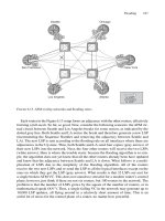
lookups. Figure 2.15 illustrates the concept in brief. The glue that holds these line cards
together is a single-stage crossbar that provides up to 80 Gbit/s I/O bandwidth. The succes-
sor of the 12000 Series is the 12400, which offers an increased crossbar bandwidth of
320 Gbit/s. The route processor and the crossbar fabric are designed redundant. If one com-
ponent breaks the other will take over. There are four different types of line cards for the
GSR Series, starting with Engine-0 line cards, which offer only software processing like the
VIP processors on the 7500 series. There are also Engine-2 line cards using custom ASIC
hardware and Engine-3 cards are the second generation of ASIC hardware. Finally, Engine-
4 line cards are targeted for the new high-speed fabric of the Cisco 12400 Series intended to
30 2. Router Architecture
•••
Route
processor
Active
line card
Active
line card
•••
Crossbar
fabric
Route
processor
Active
line card
Active
line card
FIGURE 2.15. The GSR 12000 Series concept is a crossbar fabric surrounded by active line cards
accommodate ASIC-supported high-speed lookups on four port OC-48/STM-16 (about
2.4 Gbps) and single port OC-192/STM-64 (about 10 Gbps) line cards.
Although Cisco Systems has to support a variety of hardware platforms, they offer an
easy-to-use uniform CLI across all platforms that enhance their popularity. The original
plan was to have a single code-base across all platforms, known as the Internetworking
Operating System (IOS).
2.4.4 Cisco IOS Routing Software
Unlike many other router operating systems, IOS is not based on any commercial real-
time OS. IOS is a complete new development written by Greg Satz and Kirk Lougheed,
early Cisco software engineers. There were some ideas inspired from TOPS-20, an
ancient DEC operating system, but that was about it. The biggest issue with IOS today is
its monolithic structure. IOS is not even a complete operating system in the sense of
UNIX or Windows. IOS is more like a single program that runs on a dedicated piece of
hardware. IOS does not include virtual memory protection, nor can new processes be
added at runtime. The lack of virtual memory protection is the main reason why IOS
crashes typically affect the entire machine and not just individual subsystems: there is
just a single program running and no partitioning at all. There are no demarcation points,
things like kernels, user processes and schedulers. IOS is just a single big program that
is executed from startup to shutdown.
IOS is based on a 20-year-old concept, and its main weakness is this monolithic code
structure. Until the runtime environment is changed, it will be hard if not impossible to
re-engineer the system for future requirements, such as the carrier-class availability
(known as “5 nines”) that the public infrastructure needs and deserves. Because of the
huge amount of code that needs to be carried from one product variation to the next, the
best thing to do with IOS is probably to start from scratch.
This desire to change the monolithic router OS infrastructure and to develop a second-
generation routing operating system was the genesis for newer companies like Juniper
Networks. It will come as no surprise to learn that the initial engineers writing the
JUNOS operating system were experienced engineers drafted from Cisco having the
insight (gathered from direct experience) into which design pitfalls to avoid in order to
build a stable, scalable router.
2.4.5 Juniper Networks M-Series Routers
Juniper Networks M-series routers were the first in the industry to offer a true decoupling
of the forwarding plane and control plane. Figure 2.16 shows the Juniper Networks sep-
aration between Routing Engines (RE) and a Packet Forwarding Engine (PFE). The
Routing Engine is an off-the-shelf Intel-based industry-standard PC platform with a very
small form factor. The link between the RE and the PFE is a standard Fast Ethernet link
that runs a proprietary protocol called the Trivial Network Protocol (TNP). TNP takes
care of the proper care and feeding of the lookup and queuing ASICs, and also retrieves
(for example) interface statistics from the chassis. TNP also provides a tunnelled mode
where it carries packets sourced by the RE targeted for an interface (such as routing
Router Technology Examples 31
protocol packets). The tunnel mode is necessary so that the RE can communicate with
the outside world. It is worth noting that no matter what JUNOS feature is turned on, no
transit traffic ever gets processed by the RE. The RE only needs to take care of control
traffic. Additionally, all traffic from the PFE to the RE is rate-limited in order to protect
the RE under all circumstances, even during denial-of-service attacks.
The PFE is a collection of custom ASICs interconnected by a distributed, shared mem-
ory fabric. The line cards follow a similar physical approach to the VIP adapters of Cisco.
There are Flexible PIC Concentrators (FPCs), which are carrier cards for the Physical
Interface Cards (PICs). The PIC itself can be compared to a PA in the VIP architecture.
Essentially, these are simple devices that just take care of proper physical framing, CRC
checksumming and alarm generation (SONET/SDH PICs). But in contrast to the VIP
architecture, the FPCs do not perform any route-lookup. The FPCs’ ASICs only process
a packet at Layer-2, strip all Layer-2 framing and then pass the packet to a central route
lookup chip, the Internet Processor 2 (IP2). The IP2 can only do route lookups and
packet filter lookups. Once a next-hop matching any field in the IP header (typically, but
not always, only the destination IP address) is found, the outbound FPC fetches, queues
and finally transmits the packet to the PIC. The PIC again performs only Layer-1 related
functions like checksumming and so on. The IP2 FIB table structure has been optimized
for update friendliness. In fact, a change in next-hop under full load does not cause a sin-
gle packet to drop! The FIB table size is 16 MB, providing room for about 1100K routes,
many times more than the Internet could need for years to come.
Feature-rich lookup, classification hardware, and a clear architectural avoidance of
transit traffic on the RE is the foundation for the elusive goal of true separation of the for-
warding plane and the control plane.
32 2. Router Architecture
Routing
engine
FPC
0
FPC
n
IP II
Input
Output
Packet
Forwarding
Engine
PIC 0
PIC 1
PIC 2
PIC 3
PIC 0
PIC 1
PIC 2
PIC 3
FIGURE 2.16. The M-Series encompasses a truly separated forwarding and control plane
2.4.6 JUNOS Routing Software
The JUNOS operating system is built around a FreeBSD 4.2-STABLE UNIX operating
system. The kernel is different to the usual FreeBSD kernel. Special care has been taken
to ensure scalability and the kernel is modified to support multiple routing tables, mil-
lions of routes and thousands of interfaces. Because UNIX offers full virtual memory
protection, the system is split up in many different user processes, as illustrated in Figure
2.17. The routing code is still bundled in a single process for all the routing protocols
across all routing instances, so the issue of scheduling is still present. If a large wave of
BGP updates hits the system, it is possible to miss sending IGP Hellos. But the UNIX-
based package also provides a way around this issue. There is a dedicated daemon
(server process) in JUNOS called the Periodic Packet Management Daemon (PPMD).
The IGPs register with PPMD, which sends out the IGP Hellos on their behalf. PPMD
completely offloads Hello processing from the RPD, and the RPD does not need to han-
dle periodic Hellos at all. The RPD is notified by PPMD if an important event like an
adjacency expiration occurs. PPMD runs with the highest scheduling priority in the system
and may pre-empt any process to make sure that every IGP Hello is delivered in time.
In summary, JUNOS is a true example of a second-generation router operating
System. Many lessons learned from deployment experience with Cisco IOS have been
incorporated into the software. The software is modular in order to overcome the fate-
sharing problems in monolithic designs. At the time of writing, the number of active
processes in a functioning router was 37, an extraordinary number. Partitioning the code
carefully ensures that each single subsystem becomes maintainable and protects the
overall system from avalanche effects caused by local bugs.
2.5 Conclusion
The evolution of the Internet is so fast that it is difficult for core routers to keep up.
Both forwarding user traffic and processing control traffic in a network that doubles in
speed and size every nine months is a daunting task. To tackle the problem of scaling,
Conclusion 33
Kernel
Kernel
rpd
rpd
mgd
mgd
chassid
chassid
…
ppmd
ppmd
Real-time
code pieces
FIGURE 2.17. JUNOS software is partitioned across many user level processes
one common technique is repeatedly used: partitioning. The first occurrence of parti-
tioning is the Internet routing paradigm itself. Hosts need to perform more dissimilar
functions than routers have to do. Partitioning is the tool of choice to scale router scala-
bility problems. In modern routers, the control plane has been separated from the
forwarding plane. This separation does not rely on shared resources like CPU cycles and
memory. Next, clever ways of manipulating forwarding table structures while forward-
ing traffic at full speed have been developed. Partitioning the route lookup and table
maintenance functions addressed the challenges of an ever-and-yet-never-quite converg-
ing Internet. Finally, control plane software has been partitioned twice. First, the interac-
tion and memory protection of routing software inside the system is secured via a kernel
that each process relies upon, greatly minimizing the impact of broken software. Second,
the routing protocols are split up into a real-time component and a non-real-time com-
ponent, further improving convergence time granularity as well as removing a lot of
complexity from the routing code.
All in all, partitioning is the prevailing scaling method that helps to scale the Internet
and its building block, the router.
34 2. Router Architecture
3
Introduction to the IOS and JUNOS
Command Line Interface
35
In the router world, ISPs and carriers got used to the fact that routers are configured and
managed using an ASCII-based command line interface. Even if this seems scary the first
time, especially when used to fancy graphical user interfaces (GUI), command line inter-
faces give unmatched control over the router and provide a powerful troubleshooting
tool.
The Internet is a network that is constantly under flux – somebody somewhere is always
changing something. Moreover, new protocol standards evolve, new releases of routing
software are deployed, peering policy may change as a result of business constraints or
acquisitions, and so on. All this makes for a challenging environment that, at least not up
to now, could be modelled in the form of a GUI. In this chapter we will give a basic
overview of how to interact with this kind of interface. You will learn in this chapter
how to upload a new configuration, how to query IS-IS related status and finally how to
troubleshoot and debug adjacency formation and link-state databases.
3.1 Common Properties of Command Line Interfaces (CLI)
When Cisco Systems shipped it first product called “ISH” back in 1986, no one imagined
that the company would be redefining how operators interacted with routers for the next
two decades. At first sight a command line interface might look primitive; however, there
are important aspects and elements that helped the company achieve its breathtaking
success. There are many theories about why Cisco Systems got to where they are in the
industry today. From a technical viewpoint, two key properties helped people feel com-
fortable with the Cisco router’s interface. The first is that after changing the router’s con-
figuration, everything was written into a single file that is kept in the Non-Volatile RAM
(NVRAM) of the router. Virtually everything that the router does, for example running
routing protocols, performing access control, or using static routes, is controlled by this
single file. The second important aspect is that the router’s configuration file was an
ASCII file and is therefore human-readable. Unlike other router companies who stored
their configuration file in binary form, the IOS configuration files could be read out on
the fly and everybody understood exactly what the router was supposed to do.
There are two other main advantages of single ASCII configuration files. First, support
gets easier. It is a matter of fact that a large fraction of support calls are configuration
related. An ASCII configuration file enabled operators to simply copy and paste their
router configuration into an email when requesting support. The Technical Assistance
Centre (TAC) could then very quickly see if this was a configuration issue or if the soft-
ware had a bug and further analysis of the problem was required. There are even those in
the industry who argue that ASCII-based configuration files make the support organiza-
tion scale more effectively and work most efficiently.
The second main advantage is that customers did not need to have a live router to gen-
erate configuration files. If the router’s configuration was stored in binary form, there is
no opportunity for a third-party application or a “quick-hack” script to generate a valid
configuration file. Router configurations that could be generated by standard UNIX tools
like SED, AWK and PERL were a first-generation way of eventually making a provi-
sioning API available for configuration robot tools.
Perhaps Proteon (an ancient router vendor from the 1980s) had an interface that pro-
vides the best example of how not to do router configuration:
•
Configuration was purely done using menus that never showed you where you were
in the configuration statement hierarchy.
•
Configuration and show commands had a totally different look and feel (for those who
are familiar with this, just recall the jumping between T5 and T6 command shells).
•
Everything was stored in a binary file.
•
There was no possibility to employ external provisioning tools.
Cisco overtook Proteon in the market at the end of 1980s for various reasons. But one
reason was definitely the odd command line interface of Proteon routers. Not that a sound
CLI automatically paves the way for success in the router industry, but it clearly does help.
The two ASCII-based command line interfaces of IOS and JUNOS are similar to each
other in some respects, and different in others. The following sections highlight these
common elements. Then the differences between IOS and JUNOS (and also the intended
improvements JUNOS made to IOS) will be discussed as well.
Routers are typically accessed in three ways:
•
RS232 serial console
•
In-band access via telnet or Secure Shell (SSH)
•
Out-of-band access via telnet or SSH.
Once you have logged on the router, there are two general modes of talking to the router.
The first one is called the operational mode. This mode is mainly used to explore what the
router and its environment are doing, what routes are being installed in the system and if
interfaces are carrying traffic. The other mode is the configuration mode. In the configura-
tion mode the router’s behaviour is controlled, for example, what IP address does it have,
what routing protocols parameters are used, who can access the router or network, and so on.
3.1.1 Operational Mode
Once you log into a router you usually find yourself in operational mode. The trailing
“Ͼ” sign indicates that you are working in operational mode. In JUNOS the prompt
looks like this:
hannes@New-York>
36 3. Introduction to the IOS and JUNOS Command Line Interface
And for IOS, the prompt would look like this:
London>
What you will always see is the hostname (the name of the router) followed by the
“Ͼ” sign. In JUNOS you also see the username followed by the “@” sign before the
hostname. Now you can issue commands to the router. The commands are organized in
a hierarchical fashion as shown in Figure 3.1. The more arguments a command has, the
more specific the command gets. For instance, a show isis database London
just shows a single link-state database (LSDB) entry, while show isis database
shows all LSDB entries.
hannes@Frankfurt> show isis database London
IS-IS level 2 link-state database:
LSP ID Sequence Checksum Lifetime Attributes
London.00-00 0x1af 0xa977 25314 L1 L2
1 LSPs
hannes@Frankfurt> show isis database
IS-IS level 1 link-state database:
IS-IS level 2 link-state database:
LSP ID Sequence Checksum Lifetime Attributes
London.00-00 0x1af 0xa977 25314 L1 L2
Amsterdam.00-00 0x1a7 0x3dd0 31088 L1 L2
New-York.00-00 0x1a2 0x16f5 46510 L1 L2
Penssauken.00-00 0x19a 0x3ec 5184 L1 L2
408 LSPs
The arguments for a command are separated by a simple blank. Sometimes the router
has too few arguments and this forms an unambiguous command. Typically, routers
complain about an ambiguous command with a prompt:
hannes@Frankfurt> show isis
syntax error, expecting <command>.
Common Properties of Command Line Interfaces 37
show
bgp isis chassisinterface
community detailas-path
clear help
route
FIGURE 3.1. The command line space is organized in a hierarchical fashion
This is from a router running JUNOS and
Munich>show isis
% Incomplete command.
is from an IOS-based router. However, there is an easy way to discover what kinds of
commands the router gives you: context-sensitive help.
3.1.1.1 Context-sensitive Help
At any time, you can enter a question mark (?) at the user prompt, which makes the CLI
display all the options that are available at this point in the command-line hierarchy:
hannes@Frankfurt> show isis ?
Possible completions:
adjacency Show the IS-IS adjacency database
database Show the IS-IS link-state database
hostname Show IS-IS hostname database
interface Show IS-IS interface information
route Show the IS-IS routing table
spf Show information about IS-IS SPF calculations
statistics Show IS-IS performance statistics
You will see the keywords that are available, plus a brief descriptive text about what
kind of information is displayed by the respective option.
If the question mark is keyed in the middle of an argument, the CLI shows you what
valid completions are still left. Note above that there are two keywords after show isis
starting with the letter “S”. The keywords “spf” and “statistics” both start with the same
letter. What you can do is issue a show isis s command and then type the question mark:
hannes@Frankfurt> show isis s?
Possible completions:
spf Show information about IS-IS SPF calculations
statistics Show IS-IS performance statistics
The router shows you the two possible completions. If there are no valid completions
then the router simply responds with:
hannes@Frankfurt > show isis j?
No valid completions
Sometimes the keywords available in the CLI can be very long and the command line
interfaces often offer shortcuts to the keywords. That is, it is not really a shortcut, it is
more that the command line parser looks to see if your input is unambiguous and then
accepts the keyword. So the commands do not have to be specified to the full extent:
London> sh is d
produces the same output as:
London> show isis database
38 3. Introduction to the IOS and JUNOS Command Line Interface
3.1.1.2 Auto-complete
Sometimes these shortcuts are also known as auto-complete functionality. It is not quite
the same thing, however. What auto-complete means is that you can press the ϽTABϾ key
every time you want to check if you have supplied enough characters for a keyword so
the command is unambiguous. For example, if you enter:
London> show i<TAB>
then you get:
London> show i
In other words, nothing happens if the letters supplied are ambiguous. However, if you
supply enough letters like:
London> show is<TAB>
then you get:
London> show isis
Auto-complete proved to be a powerful tool for experienced users quickly needing
output, for instance, when troubleshooting a network problem.
The second major mode of router CLI operation is the configuration mode that con-
trols the router’s behaviour.
3.1.2 Configuration Mode
You can switch from the operational mode to the configuration mode by issuing commands
like configure or configure terminal. On JUNOS routers you see that you are
now in configuration mode because the prompt has been changed from “Ͼ” to “#”
hannes@New-York> configure
Entering configuration mode
[edit]
hannes@New-York#
You also can see that you are in the configuration mode because each time you press
the ϽENTERϾ key your prompt is prepended by [EDIT], which always indicates that
you are in the configuration mode.
On IOS platforms you cannot get directly to configuration mode. You first get into
what is called the privileged enable mode.
London>enable
Password: *******
London#conf terminal
Enter configuration commands, one per line. End with CNTL/Z.
London(config)#
Just as in JUNOS there is the # indication in the prompt that tells you that you are in
configuration mode. You also see the config keyword in parentheses after the router’s
hostname and the prompt.
Common Properties of Command Line Interfaces 39
The configuration mode CLI also has a hierarchy, as described in the operational
mode, for show commands. The prompt again indicates what part of the hierarchy the
operator is configuring. For example, if you want to configure parameters that are related
to the IS-IS subsystem, you specify simply router isis and then the system puts you
in the router isis context.
London#conf t
Enter configuration commands, one per line. End with CNTL/Z.
London(config)#router isis
London(config-router)#
You see that you are working in a different context because the prompt changes. A simi-
lar thing happens to the prompt in JUNOS command line interfaces:
hannes@New-York> configure
Entering configuration mode
[edit]
hannes@New-York# edit protocols isis
[edit protocols isis]
hannes@New-York#
The information in the square brackets is called the editing context. A simple [edit]
means that you are on the top-level of the configuration hierarchy. When you move
around in the hierarchy using the edit command, the prompt changes accordingly.
3.1.3 Emacs Style Keyboard Sequences
There are people in the industry who believe that the UNIX Emacs editor is a problem
itself; there are others who believe it is a solution to all kind of problems. While the authors
generally like the highly customizable nature of what is probably the most powerful editor
around, there are others who complain that it is hard to configure and make it do what you
want . One thing about Emacs that is distinctive is the way that you move the cursor around
on the screen. Emacs has certain key-combinations that can put the cursor at the beginning
of a line or at the end of a line, and so on. Moving quickly around and editing a command
really speeds up the way of talking to the router. Figure 3.2 shows the most commonly-used
Emacs sequences. CTRL-A and CTRL-E for moving to the beginning or end of a line
are the ones used most often. IOS and JUNOS both implement the Emacs keystroke
sequences, and once you are used to it, it greatly speeds up administering the router.
3.1.4 Debugging
Modern routers give you a vast amount of debugging options where you can trace virtu-
ally everything that the router is doing. Both JUNOS and IOS have a rich tracing facility
to show what the routing software is doing. Each protocol has its very own knobs that
you can turn on. Similar to operational mode and configuration mode, there is also a hier-
archy as to what kind of feature or protocols can be debugged. The purpose of turning on
the debugging facility is to help you during the troubleshooting process. Unfortunately, the
way that the debuggers are managed in each is very different and will be discussed in the
IOS and JUNOS specific sections. The important point is that both platforms give you a
powerful debugging facility for troubleshooting complex networking problems.
40 3. Introduction to the IOS and JUNOS Command Line Interface
3.1.5 IP Troubleshooting Tools
Router operation systems like IOS and JUNOS also have standard IP troubleshooting tools
(like ping and traceroute) on board. The ping and traceroute utilities often have been
enhanced for core-routing applications. One example of such enhancements is the ability
to specify the routing table which the system should use to determine the outgoing interface.
Other examples are the ability to manually specify the source IP address or to bypass a rout-
ing table. So both the ping and traceroute utilities are available, but have some enhancements
far beyond the off-the-shelf ping and traceroute commands that are included with host
operating systems. So when you first use them, make sure to use the online help function
by keying the question mark to see what kind of additional options the system offers.
3.1.6 Routing Policy
Even if this is a book about IS-IS, there are many times when the IS-IS protocol needs to
interact with other routing protocols, or even transfer prefix reachability information
from one protocol to the other. Both JUNOS and IOS have a rich set of software features
that control the flow of routing information between protocols. The software is very ver-
satile and in the JUNOS case it even has a “language” all of its own that controls the met-
rics and properties of a routing advertisement depending on the administrative policy in
the network. In the IOS and JUNOS specific sections you will see specifics of IOS and
JUNOS routing policy implementations.
3.1.7 Logging
Sometimes during troubleshooting you are more interested in past events than current status.
So it may be important to know when a BGP session last flapped or when a SONET/SDH
link went down. Both IOS and JUNOS allow you to log events to three places:
•
Console (if there is an emergency/urgent action) that every user should know
•
Local log file
•
Central Logging Hosts (Syslog)
Common Properties of Command Line Interfaces 41
CTRL-B
CTRL-A
CTRL-F
CTRL-E
hannes@New-York> show isis database
CTRL-W
hannes@New-York> show isis database
hannes@New-York> show isis database
hannes@New-York> show isis database
hannes@New-York> show isis database
hannes@New-York> show isis
FIGURE 3.2. IOS encompasses Emacs style keystrokes for faster navigation of the cursor