Parallel Programming: for Multicore and Cluster Systems- P10 pdf
Bạn đang xem bản rút gọn của tài liệu. Xem và tải ngay bản đầy đủ của tài liệu tại đây (231.09 KB, 10 trang )
80 2 Parallel Computer Architecture
E (exclusive) means that the cache contains the only (exclusive) copy of the mem-
ory block and that this copy has not been modified. The main memory con-
tains a valid copy of the block, but no other processor is caching this block.
If a processor requests a memory block by issuing a PrRd and if no other processor
has a copy of this memory block in its local cache, then the block is marked with
E (instead of S in the MSI protocol) in the local cache after being loaded from the
main memory with a BusRd operation. If at a later time, this processor performs
a write into this memory block, a state transition from E to M is performed before
the write. In this case, no additional bus operation is necessary. If between the local
read and write operation, another processor performs a read to the same memory
block, the local state is changed from E to S. The local write would then cause the
same actions as in the MSI protocol. The resulting protocol is called MESI protocol
according to the abbreviation of the four states. A more detailed discussion and a
detailed description of several variants can be found in [35]. Variants of the MESI
protocol are supported by many processors and the protocols play an important role
in multicore processors to ensure the coherency of the local caches of the cores.
The MSI and MESI protocols are invalidation protocols. An alternative is write-
back update protocols for write-back caches. In these protocols, after an update of
a cache block with state M, all other caches which also contain a copy of the corre-
sponding memory block are updated. Therefore, the local caches always contain the
most recent values of the cache blocks. In practice, these protocols are rarely used
because they cause more traffic on the bus.
2.7.3.3 Directory-Based Cache Coherence Protocols
Snooping protocols rely on the existence of a shared broadcast medium like a bus
or a switch through which all memory accesses are transferred. This is typically the
case for multicore processors or small SMP systems. But for larger systems, such a
shared medium often does not exist and other mechanisms have to be used.
A simple solution would be not to support cache coherence at hardware level.
Using this approach, the local caches would only store memory blocks of the local
main memory. There would be no hardware support to store memory blocks from
the memory of other processors in the local cache. Instead, software support could
be provided, but this requires more support from the programmer and is typically
not as fast as a hardware solution.
An alternative to snooping protocols are directory-based protocols. These do
not rely on a shared broadcast medium. Instead, a central directory is used to store
the state of every memory block that may be held in cache. Instead of observ-
ing a shared broadcast medium, a cache controller can get the state of a memory
block by a lookup in the directory. The directory can be held shared, but it could
also be distributed among different processors to avoid bottlenecks when the direc-
tory is accessed by many processors. In the following, we give a short overview
of directory-based protocols. For a more detailed description, we refer again to
[35, 84].
2.7 Caches and Memory Hierarchy 81
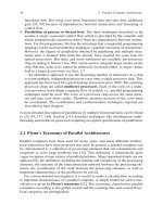
Fig. 2.36 Directory-based
cache coherency
cache
yrotceridyrotcerid
cache
interconnection network
yromemyromem
processor
processor
As example, we consider a parallel machine with a distributed memory. We
assume that for each local memory a directory is maintained that specifies for each
memory block of the local memory which caches of other processors currently store
a copy of this memory block. For a parallel machine with p processors the directory
can be implemented by maintaining a bit vector with p presence bits and a number
of state bits for each memory block. Each presence bit indicates whether a specific
processor has a valid copy of this memory block in its local cache (value 1) or
not (value 0). An additional dirty bit is used to indicate whether the local memory
contains a valid copy of the memory block (value 0) or not (value 1). Each directory
is maintained by a directory controller which updates the directory entries according
to the requests observed on the network.
Figure 2.36 illustrates the organization. In the local caches, the memory blocks
are marked with M (modified), S (shared), or I (invalid), depending on their state,
similar to the snooping protocols described above. The processors access the mem-
ory system via their local cache controllers. We assume a global address space, i.e.,
each memory block has a memory address which is unique in the entire parallel
system.
When a read miss or write miss occurs at a processor i, the associated cache
controller contacts the local directory controller to obtain information about the
accessed memory block. If this memory block belongs to the local memory and the
local memory contains a valid copy (dirty bit 0), the memory block can be loaded
into the cache with a local memory access. Otherwise, a non-local (remote) access
must be performed. A request is sent via the network to the directory controller at
the processor owning the memory block (home node). For a read miss, the receiving
directory controller reacts as follows:
• If the dirty bit of the requested memory block is 0, the directory controller
retrieves the memory block from local memory and sends it to the requesting
node via the network. The presence bit of the receiving processor i issetto1to
indicate that i has a valid copy of the memory block.
• If the dirty bit of the requested memory block is 1, there is exactly one processor
j which has a valid copy of the memory block; the presence bit of this processor
is 1. The directory controller sends a corresponding request to this processor j.
The cache controller of j sets the local state of the memory block from M to S
and sends the memory block both to the home node of the memory block and to
the processor i from which the original request came. The directory controller of
82 2 Parallel Computer Architecture
the home node stores the current value in the local memory, sets the dirty bit of
the memory block to 0, and sets the presence bit of processor i to 1. The presence
bit of j remains 1.
For a write miss, the receiving directory controller does the following:
• If the dirty bit of the requested memory block is 0, the local memory of the home
node contains a valid copy. The directory controller sends an invalidation request
to all processors j for which the presence bit is 1. The cache controllers of these
processors set the state of the memory block to I. The directory controller waits
for an acknowledgment from these cache controllers, sets the presence bit for
these processors to 0, and sends the memory block to the requesting processor i.
The presence bit of i is set to 1, the dirty bit is also set to 1. After having received
the memory block, the cache controller of i stores the block in its cache and sets
itsstatetoM.
• If the dirty bit of the requested memory block is 1, the memory block is requested
from the processor j whose presence bit is 1. Upon arrival, the memory block is
forwarded to processor i, the presence bit of i is set to 1, and the presence bit of
j is set to 0. The dirty bit remains at 1. The cache controller of j sets the state of
the memory block to I.
When a memory block with state M should be replaced by another memory block in
the cache of processor i, it must be written back into its home memory, since this is
the only valid copy of this memory block. To do so, the cache controller of i sends
the memory block to the directory controller of the home node. This one writes the
memory block back to the local memory and sets the dirty bit of the block and the
presence bit of processor i to 0.
A cache block with state S can be replaced in a local cache without sending a
notification to the responsible directory controller. Sending a notification avoids the
responsible directory controller sending an unnecessary invalidation message to the
replacing processor in case of a write miss as described above.
The directory protocol just described is kept quite simple. Directory protocols
used in practice are typically more complex and contain additional optimizations
to reduce the overhead as far as possible. Directory protocols are typically used for
distributed memory machines as described. But they can also be used for shared
memory machines. Examples are the Sun T1 and T2 processors, see [84] for more
details.
2.7.4 Memory Consistency
Cache coherence ensures that each processor of a parallel system has the same con-
sistent view of the memory through its local cache. Thus, at each point in time, each
processor gets the same value for each variable if it performs a read access. But
cache coherence does not specify in which order write accesses become visible to
the other processors. This issue is addressed by memory consistency models. These
2.7 Caches and Memory Hierarchy 83
models provide a formal specification of how the memory system will appear to
the programmer. The consistency model sets some restrictions on the values that
can be returned by a read operation in a shared address space. Intuitively, a read
operation should always return the value that has been written last. In uniprocessors,
the program order uniquely defines which value this is. In multiprocessors, different
processors execute their programs concurrently and the memory accesses may take
place in different order depending on the relative progress of the processors.
The following example illustrates the different results of a parallel program if
different execution orders of the program statements by the different processors are
considered, see also [95].
Example We consider three processors P
1
, P
2
, P
3
which execute a parallel program
with shared variables x
1
, x
2
, x
3
. The three variables x
1
, x
2
, x
3
areassumedtobe
initialized to 0. The processors execute the following programs:
processor P
1
P
2
P
3
program (1) x
1
=1; (3)x
2
=1; (5)x
3
=1;
(2) print x
2
, x
3
; (4) print x
1
, x
3
; (6) print x
1
, x
2
;
Processor P
i
sets the value of x
i
, i = 1, 2, 3, to 1 and prints the values of the
other variables x
j
for j = i. In total, six values are printed which may be 0 or 1.
Since there are no dependencies between the two statements executed by P
1
, P
2
, P
3
,
their order can be arbitrarily reversed. If we allow such a reordering and if the state-
ments of the different processors can be mixed arbitrarily, there are in total 2
6
= 64
possible output combinations consisting of 0 and 1. Different global orders may
lead to the same output. If the processors are restricted to execute their statements
in program order (e.g., P
1
must execute (1) before (2)), then output 000000 is not
possible, since at least one of the variables x
1
, x
2
, x
3
must be set to 1 before a print
operation occurs. A possible sequentialization of the statements is (1), (2), (3), (4),
(5), (6). The corresponding output is 001011.
To clearly describe the behavior of the memory system in multiprocessor envi-
ronments, the concept of consistency models has been introduced. Using a consis-
tency model, there is a clear definition of the allowable behavior of the memory
system which can be used by the programmer for the design of parallel programs.
The situation can be described as follows [165]: The input to the memory system is
a set of memory accesses (read or write) which are partially ordered by the program
order of the executing processors. The output of the memory system is a collection
of values returned by the read accesses executed. A consistency model can be seen
as a function that maps each input to a set of allowable outputs. The memory sys-
tem using a specific consistency model guarantees that for any input, only outputs
from the set of allowable outputs are produced. The programmer must write parallel
programs such that they work correctly for any output allowed by the consistency
model. The use of a consistency model also has the advantage that it abstracts
from the specific physical implementation of a memory system and provides a clear
abstract interface for the programmer.
84 2 Parallel Computer Architecture
In the following, we give a short overview of popular consistency models. For a
more detailed description, we refer to [3, 35, 84, 111, 165].
Memory consistency models can be classified according to the following two
criteria:
• Are the memory access operations of each processor executed in program order?
• Do all processors observe the memory access operations performed in the same
order?
Depending on the answer to these questions, different consistency models can be
identified.
2.7.4.1 Sequential Consistency
A popular model for memory consistency is the sequential consistency model (SC
model) [111]. This model is an intuitive extension of the uniprocessor model and
places strong restrictions on the execution order of the memory accesses. A memory
system is sequentially consistent, if the memory accesses of each single processor
are performed in the program order described by that processor’s program and if the
global result of all memory accesses of all processors appears to all processors in the
same sequential order which results from an arbitrary interleaving of the memory
accesses of the different processors. Memory accesses must be performed as atomic
operations, i.e., the effect of each memory operation must become globally visible
to all processors before the next memory operation of any processor is started.
The notion of program order leaves some room for interpretation. Program order
could be the order of the statements performing memory accesses in the source
program, but it could also be the order of the memory access operations in a
machine program generated by an optimizing compiler which could perform state-
ment reordering to obtain a better performance. In the following, we assume that the
order in the source program is used.
Using sequential consistency, the memory operations are treated as atomic oper-
ations that are executed in the order given by the source program of each processor
and that are centrally sequentialized. This leads to a total order of the memory
operations of a parallel program which is the same for all processors of the system.
In the example given above, not only output 001011 but also 111111 conforms to
the SC model. The output 011001 is not possible for sequential consistency.
The requirement of a total order of the memory operations is a stronger restriction
as has been used for the coherence of a memory system in the last section (p. 76).
For a memory system to be coherent it is required that the write operations to the
same memory location are sequentialized such that they appear to all processors
in the same order. But there is no restriction on the order of write operations to
different memory locations. On the other hand, sequential consistency requires that
all write operations (to arbitrary memory locations) appear to all processors in the
same order.
2.7 Caches and Memory Hierarchy 85
The following example illustrates that the atomicity of the write operations is
important for the definition of sequential consistency and that the requirement of a
sequentialization of the write operations alone is not sufficient.
Example Three processors P
1
, P
2
, P
3
execute the following statements:
processor P
1
P
2
P
3
program (1) x
1
= 1; (2) while(x
1
== 0); (4) while(x
2
== 0);
(3) x
2
= 1; (5) print(x
1
);
The variables x
1
and x
2
are initialized to 0. Processor P
2
waits until x
1
has value
1 and then sets x
2
to 1. Processor P
3
waits until x
2
has value 1 and then prints the
value of x
1
. Assuming atomicity of write operations, the statements are executed in
the order (1), (2), (3), (4), (5), and processor P
3
prints the value 1 for x
1
, since write
operation (1) of P
1
must become visible to P
3
before P
2
executes write operation
(3). Using a sequentialization of the write operations of a variable without requir-
ing atomicity and global sequentialization as is required for sequential consistency
would allow the execution of statement (3) before the effect of (1) becomes visible
to P
3
. Thus, (5) could print the value 0 for x
1
.
To further illustrate this behavior, we consider a directory-based protocol and
assume that the processors are connected via a network. In particular, we consider a
directory-based invalidation protocol to keep the caches of the processors coherent.
We assume that the variables x
1
and x
2
have been initialized to 0 and that they
are both stored in the local caches of P
2
and P
3
. The cache blocks are marked as
shared (S).
The operations of each processor are executed in program order and a memory
operation is started not before the preceding operations of the same processor have
been completed. Since no assumptions on the transfer of the invalidation messages
in the network are made, the following execution order is possible:
(1) P
1
executes the write operation (1) to x
1
. Since x
1
is not stored in the cache of
P
1
, a write miss occurs. The directory entry of x
1
is accessed and invalidation
messages are sent to P
2
and P
3
.
(2) P
2
executes the read operation (2) to x
1
. We assume that the invalidation mes-
sage of P
1
has already reached P
2
and that the memory block of x
1
has been
marked invalid (I) in the cache of P
2
. Thus, a read miss occurs, and P
2
obtains
the current value 1 of x
1
over the network from P
1
. The copy of x
1
in the main
memory is also updated.
After having received the current value of x
1
, P
1
leaves the while loop and
executes the write operation (3) to x
2
. Because the corresponding cache block
is marked as shared (S) in the cache of P
2
, a write miss occurs. The directory
entry of x
2
is accessed and invalidation messages are sent to P
1
and P
3
.
(3) P
3
executes the read operation (4) to x
2
. We assume that the invalidation mes-
sage of P
2
has already reached P
3
. Thus, P
3
obtains the current value 1 of x
2
over the network. After that, P
3
leaves the while loop and executes the print
operation (5). Assuming that the invalidation message of P
1
for x
1
has not yet
reached P
3
, P
3
accesses the old value 0 for x
1
from its local cache, since the
86 2 Parallel Computer Architecture
corresponding cache block is still marked with S. This behavior is possible if
the invalidation messages have different transfer times over the network.
In this example, sequential consistency is violated, since the processors observe dif-
ferent orders of the write operation: Processor P
2
observes the order x
1
= 1, x
2
= 1
whereas P
3
observes the order x
2
= 1, x
1
= 1 (since P
3
gets the new value of x
2
,
but the old value of x
1
for its read accesses).
In a parallel system, sequential consistency can be guaranteed by the following
sufficient conditions [35, 45, 157]:
(1) Every processor issues its memory operations in program order. In particular,
the compiler is not allowed to change the order of memory operations, and no
out-of-order executions of memory operations are allowed.
(2) After a processor has issued a write operation, it waits until the write operation
has been completed before it issues the next operation. This includes that for a
write miss all cache blocks which contain the memory location written must be
marked invalid (I) before the next memory operation starts.
(3) After a processor has issued a read operation, it waits until this read operation
and the write operation whose value is returned by the read operation have been
entirely completed. This includes that the value returned to the issuing processor
becomes visible to all other processors before the issuing processor submits the
next memory operation.
These conditions do not contain specific requirements concerning the interconnec-
tion network, the memory organization, or the cooperation of the processors in the
parallel system. In the example from above, condition (3) ensures that after reading
x
1
, P
2
waits until the write operation (1) has been completed before it issues the next
memory operation (3). Thus, P
3
always reads the new value of x
1
when it reaches
statement (5). Therefore, sequential consistency is ensured.
For the programmer, sequential consistency provides an easy and intuitive model.
But the model has a performance disadvantage, since all memory accesses must be
atomic and since memory accesses must be performed one after another. There-
fore, processors may have to wait for quite a long time before memory accesses
that they have issued have been completed. To improve performance, consistency
models with fewer restrictions have been proposed. We give a short overview in the
following and refer to [35, 84] for a more detailed description. The goal of the less
restricted models is to still provide a simple and intuitive model but to enable a more
efficient implementation.
2.7.4.2 Relaxed Consistency Models
Sequential consistency requires that the read and write operations issued by a pro-
cessor maintain the following orderings where X → Y means that the operation X
must be completed before operation Y is executed:
2.7 Caches and Memory Hierarchy 87
• R → R: The read accesses are performed in program order.
• R → W : A read operation followed by a write operation is executed in program
order. If both operations access the same memory location, an anti-dependence
occurs. In this case, the given order must be preserved to ensure that the read
operation accesses the correct value.
• W → W : The write accesses are performed in program order. If both operations
access the same memory location, an output dependence occurs. In this case, the
given order must be preserved to ensure that the correct value is written last.
• W → R: A write operation followed by a read operation is executed in program
order. If both operations access the same memory location, a flow dependence
(also called true dependence) occurs.
If there is a dependence between the read and write operations the given order
must be preserved to ensure the correctness of the program. If there is no such
dependence, the given order must be kept to ensure sequential consistency. Relaxed
consistency models abandon one or several of the orderings required for sequential
consistency, if the data dependencies allow this.
Processor consistency models relax the W → R ordering to be able to par-
tially hide the latency of write operations. Using this relaxation, a processor can
execute a read operation even if a preceding write operation has not yet been
completed if there are no dependencies. Thus, a read operation can be performed
even if the effect of a preceding write operation is not visible yet to all proces-
sors. Processor consistency models include total store ordering (TSO model) and
processor consistency (PC model). In contrast to the TSO model, the PC model
does not guarantee atomicity of the write operations. The differences between
sequential consistency and the TSO or PC model are illustrated in the following
example.
Example Two processors P
1
and P
2
execute the following statements:
processor P
1
P
2
program (1) x
1
=1; (3)x
2
=1;
(2) print(x
2
); (4) print(x
1
);
Both variables x
1
and x
2
are initialized to 0. Using sequential consistency, state-
ment (1) must be executed before statement (2), and statement (3) must be executed
before statement (4). Thus, it is not possible that the value 0 is printed for both x
1
and x
2
. But using TSO or PC, this output is possible, since, for example, the write
operation (3) does not need to be completed before P
2
reads the value of x
1
in (4).
Thus, both P
1
and P
2
may print the old value for x
1
and x
2
, respectively.
Partial store ordering (PSO) models relax both the W → W and the W → R
ordering required for sequential consistency. Thus in PSO models, write opera-
tions can be completed in a different order as given in the program if there is
no output dependence between the write operations. Successive write operations
can be overlapped which may lead to a faster execution, in particular when write
misses occur. The following example illustrates the differences between the different
models.
88 2 Parallel Computer Architecture
Example We assume that the variables x
1
and flag are initialized to 0. Two proces-
sors P
1
and P
2
execute the following statements:
processor P
1
P
2
program (1) x
1
= 1; (3) while(flag == 0);
(2) flag = 1; (4) print(x
1
);
Using sequential consistency, PC, or TSO, it is not possible that the value 0 is
printed for x
1
. But using the PSO model, the write operation (2) can be completed
before x
1
= 1. Thus, it is possible that the value 0 is printed for x
1
in statement (4).
This output does not conform to intuitive understanding of the program behavior in
the example, making this model less attractive for the programmer.
Weak ordering models additionally relax the R → R and R → W orderings.
Thus, no completion order of the memory operations is guaranteed. To support pro-
gramming, these models provide additional synchronization operations to ensure
the following properties:
• All read and write operations which lie in the program before the synchronization
operation are completed before the synchronization operation.
• The synchronization operation is completed before read or write operations are
started which lie in the program after the synchronization operation.
The advent of multicore processors has led to an increased availability of parallel
systems and most processors provide hardware support for a memory consistency
model. Often, relaxed consistency models are supported, as is the case for the Pow-
erPC architecture of IBM or the different Intel architectures. But different hardware
manufacturers favor different models, and there is no standardization as yet.
2.8 Exercises for Chap. 2
Exercise 2.1 Consider a two-dimensional mesh network with n rows and m columns.
What is the bisection bandwidth of this network?
Exercise 2.2 Consider a shuffle–exchange network with n = 2
k
nodes, k > 1. How
many of the 3 · 2
k−1
edges are shuffle edges and how many are exchange edges?
Draw a shuffle–exchange network for k = 4.
Exercise 2.3 In Sect. 2.5.2, p. 35, we have shown that there exist k independent
paths between any two nodes of a k-dimensional hypercube network. For k = 5,
determine all paths between the following pairs of nodes: (i) nodes 01001 and
00011; (ii) nodes 00001 and 10000.
Exercise 2.4 Write a (sequential) program that determines all paths between any
two nodes for hypercube networks of arbitrary dimension.
Exercise 2.5 The RGC sequences RGC
k
can be used to compute embeddings of dif-
ferent networks into a hypercube network of dimension k. Determine RGC
3
,RGC
4
,
2.8 Exercises for Chap. 2 89
and RGC
5
. Determine an embedding of a three-dimensional mesh with 4 × 2 × 4
nodes into a five-dimensional hypercube network.
Exercise 2.6 Show how a complete binary tree with n leaves can be embedded into
a butterfly network of dimension log n. The leaves of the trees correspond to the
butterfly nodes at level log n.
Exercise 2.7 Construct an embedding of a three-dimensional torus network with
8 × 8 × 8 nodes into a nine-dimensional hypercube network according to the con-
struction in Sect. 2.5.3, p. 39.
Exercise 2.8 A k-dimensional Bene
ˇ
s network consists of two connected k-dimen-
sional butterfly networks, leading to 2k + 1 stages, see p. 45. A Bene
ˇ
s network
is non-blocking, i.e., any permutation between input nodes and output nodes can
be realized without blocking. Consider an 8 × 8 Bene
ˇ
s network and determine the
switch positions for the following two permutations:
π
1
=
01234567
01243576
,π
2
=
01234567
27460531
.
Exercise 2.9 The cross-product G
3
= (V
3
, E
3
) = G
1
⊗ G
2
of two graphs G
1
=
(V
1
, E
1
) and G
2
= (V
2
, E
2
) can be defined as follows:
V
3
= V
1
× V
2
and E
3
={((u
1
, u
2
), (v
1
,v
2
)) | ((u
1
= v
1
) and (u
2
,v
2
) ∈ E
2
)or
((u
2
= v
2
) and (u
1
,v
1
) ∈ E
1
)}. The symbol
can be used as abbreviation with the
following meaning:
b
i=a
G
i
= ((···(G
a
⊗ G
a+1
) ⊗···) ⊗ G
b
).
Draw the following graphs and determine their network characteristics (degree,
node connectivity, edge connectivity, bisection bandwidth, and diameter):
(a) linear array of size 4 ⊗ linear array of size 2,
(b) two-dimensional mesh with 2 ×4 nodes ⊗ linear array of size 3,
(c) linear array of size 3 ⊗ complete graph with 4 nodes,
(d)
4
i=2
linear array of size i,
(e)
k
i=1
linear array of size 23. Draw the graph for k = 4, but determine the charac-
teristics for general values of k.
Exercise 2.10 Consider a three-dimensional hypercube network and prove that
E-cube routing is deadlock free for this network, see Sect. 2.6.1, p. 48.
Exercise 2.11 In the directory-based cache coherence protocol described in
Sect. 2.7.3, p. 81, in case of a read miss with dirty bit 1, the processor which has