An Encyclopedia of the History of Technology part 34 docx
Bạn đang xem bản rút gọn của tài liệu. Xem và tải ngay bản đầy đủ của tài liệu tại đây (100.28 KB, 10 trang )
PART TWO: POWER AND ENGINEERING
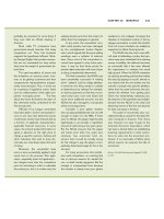
312
Figure 5.13
(a) The air-standard Diesel (modified Carnot cycle) plotted on coordinates of
pressure (P) and volume (V). The true Carnot cycle (1'), (2'), (3'), (1') was
modified by Diesel as follows: (i) expansion was terminated at point (5) in order
to provide a cylinder of reasonable dimensions (shown solid in the lower
diagram, with the dashed lines showing the cylinder dimensions required by the
true Carnot cycle); (ii) the constant temperature heat addition process (3')-(4) of
the true Carnot cycle was replaced by the constant pressure heat addition process
(3)-(4) in engines built after 1893 when it was found in the prototype to be
impossible to produce a constant temperature combustion process.
STEAM AND INTERNAL COMBUSTION ENGINES
313
(b) The air-standard compression ignition cycle plotted on coordinates of
pressure (P) and volume (V). The heat addition (combustion in the real
engine) processes tend to be different depending on the method of fuel
injection. Research by Ricardo showed that fuel injected by air is much more
finely divided than that resulting from solid injection, so burning is very fast
and the rate of combustion can be controlled by the rate of fuel admission.
Consequently, the pressure-volume diagram follows the path (2)–(3). With
solid injection there is a delay before combustion starts, this is followed by a
rapid rise in pressure (2')–(3'). At point (3') the pressure and temperature of
the cylinder contents are so high that the remaining fuel ignites on entry,
and, as with air injection, the rate of burning depends on the rate of fuel
supply (3')–(4').
divided spray, at the end of the compression process, and is ignited by contact
with the high temperature compressed air in the cylinder.
Diesel’s original proposal, made in about 1890, was for an engine working
on the Carnot cycle (see Appendix, p. 342), with a compression ratio of 50:1, a
maximum pressure of 253bar (3675psi) and temperature of 800°C (1470°F),
giving an air standard efficiency of 0.73 (Figure 5.13 (a)). However, the mean
effective pressure of the proposed cycle was very small, which meant that a
slight deviation from the design conditions would prevent the engine from
operating because it was unable to overcome the internal friction.
In 1892 the Maschinenfabrik Augsburg (later the Maschinenfabrik
Augsburg-Nürnberg or MAN) contracted with Diesel to construct an
experimental engine with a 15:1 design compression ratio in exchange for
manufacturing rights. This engine was tested between July and September
1893. It was not able to run under its own power because the friction power
exceeded the engine power, but it did demonstrate firstly that a charge of fuel
could be ignited by compression alone; and, secondly, that when the fuel is
injected it must be broken up into minute droplets, and that this was best
achieved (at that time) if the fuel was sprayed into the cylinder by
compressed air.
In spite of the problems, the engine was sufficiently promising to attract a
number of licensing agreements in 1893. In February 1897 a fourth
experimental engine (see Figure 5.13 (a)) with a compression ratio of 11:1 was
built, which, when tested, had a brake thermal efficiency of 30.7 per cent (fuel
consumption 0.44lb mass/hphr; 0.27kg/kWhr), which was substantially higher
than any contemporary heat engine. Further licences were taken up, but the
move was premature because no licensee was able to build a reliable engine.
Consequently, between 1897 and 1902 a major development programme was
carried out by MAN to produce a satisfactory engine.
During the next ten years or so, the Diesel engine gradually found its place
in the stationary engine field with engines of 15–75kW (20–100hp) that were
more convenient and more economical than gas engines. However, mobile
application did not appear practical because of the bulky air compressor
PART TWO: POWER AND ENGINEERING
314
required to produce the fuel injection ‘air blast’ and because of the low engine
speed (piston speed: 3m/s or 590ft/min).
The modern descendant of the Diesel engine is better called a compression
ignition engine because it does not operate on Diesel’s theoretical cycle.
Furthermore, beginning in the 1920s, when solid fuel injection was introduced
(see p. 322) the mode of operation differed even more from the original Diesel
concept (see Figure 5.13 (b)).
The gas engine: 1880–1986
The history of the gas engine from 1880 onwards has two phases, the first
lasting until about 1914, and the second from about 1925 to the present.
Until 1914 the history of the gas engine is very closely tied to the available
fuel. In its earliest days (1860 to 1880) coal-gas was used (LHV: 19,371kJ/m
3
or 520BTU/ft
3
), but it was expensive and restricted the engines to power
outputs of no more than 55kW (75hp). In 1878, J.E.Dowson invented the
suction gas producer which generated a gas mixture (LHV: 5029kJ/m
3
or
135BTU/ft
3
) by the partial combustion of coal with air and steam, and costing
about one-tenth the price of coal-gas. Because its lower cost more than
compensated for its smaller heating value compared to coal-gas, the use of the
gas engine increased, along with its size (up to 75kW/100hp).
In 1895, B.H.Thwaite demonstrated at the Glasgow Iron Works that blast
furnace gas (approximate composition CO 35%, N 65%; and LHV 3725kJ/m
3
or 100BTU/ft
3
) was a suitable engine fuel, and since it was otherwise a waste
product of the iron smelting process, its small heating value was no
disadvantage. The availability of large quantities of cheap gas and the need to
drive big blast furnace blowers, resulted in the construction of extremely large
gas engines for use in iron and steel works. One of the largest was a four-
stroke cycle engine of 7500kW (10,000hp) that was installed at the South
Chicago Works of the Illinois Steel Company in 1931. Nevertheless, by about
1914 it was clear that the gas engine could not compete with the compression
ignition engine or the steam turbine.
It was the commercial exploitation of natural gas (mostly methane, with
smaller quantities of other hydrocarbons; LHV: 39,113kJ/m
3
or 1050BTU/ft
3
)
in the United States, starting in the mid-1920s, that revived the fortunes of the
gas engine. This gas has to be conveyed by pipeline from its source to its point
of use, requiring compressors located at intervals. These can be driven by
reciprocating engines (sometimes gas turbines) burning as fuel the gas being
pumped. The availability of well-developed compression ignition engines,
together with a fuel in the pipeline at a high pressure, suggested that these
engines could be adapted to burn natural gas by replacing the compression
ignition cylinder head by one incorporating a fuel injector, and either a spark
STEAM AND INTERNAL COMBUSTION ENGINES
315
plug or an oil fuel injector to provide a pilot flame, as an alternative to the
electric spark. Modern forms of this engine operate with compression ratios as
high as 13:1.
Supercharging: 1909–1930
Supercharging describes any technique intended to increase the density of the
air (oxygen) supplied to an internal combustion engine. It can be accomplished
by either raising its pressure by a compressor (‘blower’) or decreasing its
temperature by the addition of volatile liquids; however the name is usually
associated with the first method. So-called charge-air cooling has also been
considered for compression ignition engines.
Supercharging was apparently first proposed by Daimler, but was not tried until
1878 when Dugald Clerk employed it on his two-stroke gas engine (see p. 307). The
first significant use of supercharging was in aircraft engines, which operate at a low
ambient pressure. This was first proposed by Auguste Rateau in 1914, and the idea
was taken up about 1918 by, among others, S.A.Moss in the United States and
A.Büchi in Switzerland. The supercharger has also been used extensively in racing
cars, since its first application by Mercedes in 1922, to increase the power output by
an engine of a given size. High power compression ignition engines have adopted
supercharging so extensively, in order to increase the power-to-weight ratio, that
supercharged engines of this type are the rule rather than the exception.
Supercharging can be provided by piston pumps, vane pumps, Roots
compressors and the centrifugal compressor. They can be driven mechanically
off the engine crankshaft, or, where space is not limited, electric motors and
even steam turbines have been used. However, it is the gas turbine, as
originally proposed by Rateau, using the exhaust gases from the engine, and
driving a centrifugal compressor that has been the most significant
development in supercharging (nowadays commonly called turbocharging).
The application of the gas turbine driven supercharger is not simple. Firstly, if
the engine is to produce power, the gas turbine-compressor combination must
have a high efficiency (more than 55 per cent) and the temperature of the
exhaust gas entering the gas turbine must be greater than about 400°C (750°F).
Secondly, difficulties can arise because of the overlap of the opening of the intake
and exhaust valves, which is required to minimize the effects of valve and gas
inertia and is, furthermore, required in the two-stroke engine to provide adequate
scavenging. If, when this situation occurs the pressure in the exhaust manifold is
higher than the intake pressure, then back flow can occur. This situation can be
overcome in two ways. In constant pressure supercharging the volume of the
exhaust system can be made large enough to keep its pressure essentially
constant and never exceeding that in the inlet manifold. This method, invented
by Rateau in 1914, is used in aircraft engines. In pulse supercharging the exhaust
PART TWO: POWER AND ENGINEERING
316
manifold is divided so that cylinders exhausting into a particular manifold do
not produce interfering pressure pulses. Büchi devised this method in about
1925 as a result of tests that he started in 1909.
The reasons for choosing a particular supercharging technique are complex,
but in general pulse supercharging is preferred in two-stroke cycle engines,
because it makes better use of the energy in the exhaust gas, thereby
compensating for the decrease in the gap temperature caused by the excess air
necessary to ensure efficient cylinder scavenging. Pulse supercharging involves
complicated exhaust manifold arrangements, so the constant pressure method
is desirable where first costs must be minimized, as in automobile applications.
The spark ignition engine
The spark ignition engine is in almost universal use for automobiles, and it is
also used as an aircraft engine when the power and speed capabilities of the
gas-turbine are not required. The modern spark ignition engine has been
subjected in its lifetime to some of the most intensive scientific study of any
thermal prime mover because of its sensitivity to the fuel used, and because it
is a potent and very widespread source of atmospheric pollutants.
1900–1920: The high speed spark ignition engine
The need to produce a simple and reliable automobile engine led to changes in
combustion chamber shape, and increase in the number of cylinders (from
1900 to 1915), improved ignition systems, decreasing gasoline volatility, better
fuel supply systems, and forced lubrication (1908).
Combustion chambers were continually changing in order to provide an
engine that was simple to manufacture and maintain, had satisfactory power
output and fuel economy, and avoided detonation (see below). The most widely
used combustion chamber was the side-valve or L-head, which, however, had a
strong tendency to produce detonation. Research conducted by H.R.Ricardo
between 1912 and 1918 showed that the compression ratio at which detonation
first occurred could be raised from 4.0 to 4.8 if the turbulence of the air-fuel charge
was increased and the spark plug was located nearer the centre of the cylinder.
1920–1945: detonation
This particular phenomenon produces an unpleasant noise, but more
importantly, it indirectly has a deleterious effect on the fuel consumption,
because it limits the maximum useable engine compression ratio.
STEAM AND INTERNAL COMBUSTION ENGINES
317
Detonation (‘knock’) was first identified and differentiated from pre-ignition
(due to hot surfaces) in 1906 by Dugald Clerk and H.R.Ricardo. It is defined
as self-ignition of the end gas (the unburnt portion of the charge) as a
consequence of its temperature and pressure having been increased by
compression resulting from the expansion of the burning portion of the charge.
This produces high frequency oscillations in pressure, and hence the
characteristic engine noise.
Detonation first became a significant consideration in 1905 as more volatile
petrol came into use, but it was not until the First World War that it became
critical as a result of its effect on aircraft engine performance. Consequently, a
group in the United States, under the direction of C.F.Kettering of the Dayton
Metal Products Company, developed a special aviation fuel consisting of a
mixture of cyclohexane and benzene which allowed aircraft engines to operate
without detonation at compression ratios up to 8:1.
Following the war, work on solving the detonation problem adopted two
approaches: firstly, the search for a chemical additive (dope) which would
suppress detonation, was undertaken by Kettering, T.A.Boyd, and Thomas
Midgley, all of General Motors. The second approach, involving the best
combination of engine design parameters and fuel to minimize detonation, was
initiated by Ricardo. Boyd, in 1919, starting from his discovery in 1916 that
iodine could suppress detonation, found that aniline was also suitable.
However, neither compound was entirely practical (iodine was corrosive and
aniline had a bad smell). Eventually in 1921, as a result of a lengthy search,
lead tetraethyl was identified as a suitable detonation suppressant. This historic
discovery made the modern high compression spark ignition engine possible
(see Figure 5.14).
In England, Ricardo formed his own company in 1917 with the objective of
finding the combination of fuel and combustion chamber form that would
eliminate detonation. As a result he decided that the detonation tendencies of
engines and of fuels must be defined in terms of standard fuels and standard
engines. In 1924 he introduced a mixture of toluene (resists detonation) and
pure heptane (readily detonates). The detonation characteristics of a candidate
fuel could then be expressed in terms of the percentage of toluene in the
standard fuel that matches the detonation characteristics of the given fuel.
Toluene was later (1927) replaced by octane, hence the now-familiar octane
number.
Since detonation depends on the engine compression ratio, as well as the
fuel, the candidate fuel must be tested in a standard engine in which the
compression ratio may be varied while the engine is running. Ricardo was first
to build such an engine (in 1919). Eventually in 1931 a committee (the
Cooperative Fuel Research Committee) of interested parties (engine
manufacturers, oil refiners) in the United States, under the leadership of
H.L.Horning of the Waukesha Engine Company, produced a standard engine
PART TWO: POWER AND ENGINEERING
318
design, known today as the CFR Fuel Research Engine, which is now a world-
wide standard for detonation research and testing.
1945–1986: power, efficiency and cleanliness
Initially, after the war ended in 1945, engines of ever increasing power, and
mean effective pressure were produced (Figure 5.14). There was also a
progressive increase in the compression ratio (Figure 5.14) and the octane
number of available petrols. This trend was arrested by the combined effects
of environmental concerns (since 1963) and the ‘energy crisis’ (1973).
Scientific investigations, particularly in southern California, in the late
1940s and early 1950s had demonstrated that hydrocarbons, carbon
monoxide, and various oxides of nitrogen, produced by automobile spark
ignition engines, were important air pollutants. It was clear that with the
anticipated increase in the number of motor vehicles, particularly in large
urban areas, control of emissions from their engines was essential. The
Figure 5.14: Historical trend of the performance parameters of four-stroke cycle
spark ignition automotive engines 1920–85. Unfortunately, the data available to
the author were limited as shown.
The curves are based on data in C.F.Taylor The Internal Combustion Engine in Theory
and Practice, vol. 2, revised edition (The MIT Press, Cambridge, Mass., 1985) and
Automotive Industries, vol. 165, no. 6 (1985), p. 521.
STEAM AND INTERNAL COMBUSTION ENGINES
319
government of the State of California, and then the United States government,
enacted legislation on automobile emissions, and comparable regulations were
imposed in many countries outside the United States.
The environmental regulations imposed by the US government on the
automobile engine were embodied in the so-called 1963 Clean Air Act, amended
in 1968, 1970 and 1977. The practical realization of the various techniques devised
to meet the legal requirements has resulted in the need to solve some of the most
challenging technical problems presented by the internal combustion engine.
There are five main emission control methods, (a) Air injection into the
exhaust manifold to burn hydrocarbons and carbon dioxide, (b) Exhaust gas
recirculation (EGR), which lowers nitrogen oxides emitted by the engine by
diluting the intake fuel-air mixture, thus decreasing the maximum cylinder gas
temperature, (c) Oxidizing catalytic converter, which is located in the exhaust
line and assists the oxidation of hydrocarbons and carbon dioxide. In 1981 a
so-called three-way catalytic converter, which additionally converts oxides of
nitrogen to nitrogen, was introduced. This has allowed the engine to operate at
conditions suitable for minimum fuel consumption, (d) Electro-mechanical
carburettor which controls the engine fuel supply by sensing the oxygen level
in the exhaust gas before it enters the three-way catalytic converter. The sensor
and the carburettor are linked through a microcomputer to provide a control
system that maintains the air-fuel ratio at 14.6±0.2. (e) Fuel injection into the
inlet manifold or at the cylinder intake ports, which allows even more precise
control of the air-fuel ratio than the electro-mechanical carburettor.
The effort to meet emission standards in mass-produced engines has resulted
in a complicated engine that has a higher first cost and is expensive to maintain.
It is possible that this situation could be avoided if the combustion processes in
the engine cylinder could be fundamentally changed. It has been known for
some time that a marked reduction in carbon monoxide and oxides of nitrogen
emissions (but not hydrocarbons) can be obtained if the fuel-air mixture was
weaker than that required by purely chemical considerations (the so-called
stoichiometric mixture): however, the engine has a low efficiency and runs very
roughly. This can be avoided by using a stratified charge (see p. 306–7), and a
substantial effort has been made by automobile manufacturers to develop an
engine of this type. Because its operation is sensitive to variations in design and
conditions of use, it has been found difficult to employ this type of engine in a
mass-produced vehicle: the only commercially available engine in the late 1980s
was the Honda Compound Vortex Controlled Combustion (CVCC) engine.
Aircraft engines
The contribution of the aircraft engine to the development of the internal
combustion engine has been particularly important in producing engines of
PART TWO: POWER AND ENGINEERING
320
low specific weight (kg/kW). Many of the features that have contributed to this
development have reappeared in the 1980s in low specific weight automobile
engines with minimum fuel consumption and pollution.
The automobile engines available to the earliest aircraft builders (c.1900)
were too heavy and of too low power, and the first practical engines produced
by the Wright brothers (see p. 622) and by C.M.Manly for Langley’s
‘Aerodrome’ of 1903, were designed specifically for use in aeroplanes. Manly’s
engine was remarkable in having a specific weight of 1.45kg/kW (2.38lb mass/
hp), which was not improved on until the American ‘Liberty’ engine of 1918.
The Manly engine was unique in its anticipation of many features that became
standard on later aircraft engines: a radial arrangement of the cylinders with a
master connecting rod, the cam and valve gear arrangement, and crankcase,
cylinders and other parts that were machined all over to carefully controlled
dimensions.
Aircraft engines following the initial period (c.1903–14) were of two
main types. The air-cooled radial engine was based on the Gnome rotary
(cylinders rotated around the crank shaft) radial engine, which was the
most popular aircraft engine up to the First World War and was used by
both sides in the conflict. It was mostly, but not exclusively, used by
civilian aircraft operators, because of its simpler cooling arrangements. The
first large radial air-cooled engine of modern design was the Pratt and
Whitney ‘Wasp’ (1927). It employed a mechanically driven centrifugal
supercharger, as well as a forged and machined aluminium crankcase and
cylinder head.
The liquid-cooled vee engine had its origins (c.1915) in the Hispano-Suiza
engine (1.9kg/kW or 3.1lb mass/hp). The basic structure consisted of a cast
aluminium crankcase with en bloc water jackets. Initially, aircraft engines used
water for cooling, but this was changed c.1932 by the Curtiss Company in the
US when they introduced a water-ethylene glycol mixture. This boiled above
the boiling point of water, so that the higher temperature difference between
the coolant and the ambient air allowed the use of a smaller, lower drag
radiator.
The Curtiss Company, starting in 1920, developed a succession of in-
line engines, based on the Hispano-Suiza engine, which had considerable
success in racing, particularly in the Schneider Trophy sea-plane races (see
p. 630). This led the Rolls-Royce Company in Britain to design the
‘Kestrel’ engine in 1927 (1.1kg/kW or 1.77lb mass/hp), followed by the ‘R’
(for racing) type, and then the ‘Merlin’ (0.78kg/kW or 1.28lb mass/hp).
This last engine, together with the Wright ‘Cyclone’ and Wright ‘Wasp’
radial engines, represent the pinnacle of the reciprocating spark ignition
aircraft engine development.
Figure 5.15 summarizes the development of the aircraft piston engine
between 1900 and 1960.
STEAM AND INTERNAL COMBUSTION ENGINES
321
The compression ignition engine
The modern compression ignition engine is the most efficient thermal prime
mover available today, and the pollutants in the exhaust are less than those
produced by spark ignition engines. It is the engine of choice in non-aircraft
transportation applications where low operating costs are more important than
the first cost. However, the compression ignition engine was not readily
adaptable to transport applications until about 1930 when engine speeds
increased and solid injection replaced air-blast fuel injection.
Figure 5.15: Historical trend of the performance parameters of aircraft spark-
ignition engines 1900–60.
Adapted with permission from: C.F.Taylor ‘Aircraft Propulsion: A Review of the
Evolution of Aircraft Power Plants’, Smithsonian Report for 1962 (Smithsonian
Institution, Washington, D.C., 1962).