An Encyclopedia of the History of Technology part 38 potx
Bạn đang xem bản rút gọn của tài liệu. Xem và tải ngay bản đầy đủ của tài liệu tại đây (228.26 KB, 10 trang )
PART TWO: POWER AND ENGINEERING
352
discovered was in the muscle; Volta showed that it was the result of contact
between the two different metals.
Volta announced his discovery in a letter to the President of the Royal
Society in London, and the letter was published. Accompanying the letter was
a drawing of pairs of metal discs interleaved with pieces of leather or card
soaked in salt water. He referred to the discs as making a ‘pile’ (colonne in the
original French of the letter), and the term Volta’s pile has remained.
The first mass-produced battery was designed by William Cruickshank, a
lecturer at the Royal Military Academy, Woolwich, soon after 1800. He
soldered together pairs of copper and zinc plates and set them in wax in
grooves across a wooden trough. The trough was then filled with acid. Michael
Faraday used Cruickshank batteries in his early electrical researches, and in his
book Chemical Manipulation, published in 1828, he went into detail about the
right acid to use. (He recommended one volume of nitric acid, three volumes
of sulphuric acid, mixed with water to make one hundred volumes.)
The availability of a steady electric current opened up new possibilities for
research. Many people studied the properties of an electric current, especially
its chemical properties. Among the first was Humphry Davy. Born in
Penzance, Davy was first apprenticed to a surgeon-apothecary, but he was
released from his apprenticeship to take a post as assistant at the Pneumatic
Institution in Bristol, a body devoted to the study of the physiological
properties of gases. Davy’s main work there was a study of the effect of
breathing nitrous oxide (‘laughing gas’), which Davy said gave him a sensation
‘similar to that produced by a small dose of wine’.
Davy’s future lay not in Bristol but at the new Royal Institution, founded in
1799 in London, where in 1801 he was offered a post as lecturer. The purpose
of the Royal Institution was ‘to encourage the diffusion of scientific knowledge
and the general introduction of useful inventions’. It was equipped with a
lecture theatre and laboratories. Davy gave lectures which attracted large
audiences from all levels of society, but as well as teaching chemistry he
advanced it. He established the science of electrochemistry, and within a few
years had isolated the metals potassium, sodium, strontium, barium, calcium
and magnesium by electrolysis of their compounds.
In the course of his work Davy discovered the brilliant light produced by an
electric arc between two pieces of carbon connected to a suitable source of
electricity. He used the arc as a source of heat, but it seems unlikely that he
really envisaged it becoming a practical source of illumination—the limited
batteries at his disposal would have made arc lighting prohibitively expensive.
Despite their expense, chemical cells were the main source of electricity until
the development of practical generators in the 1860s. Batteries such as
Cruickshank’s had two serious defects. One was the phenomenon known as
local action, in which impurities in the zinc plate reacted electrolytically with
the zinc itself, eventually destroying the plate. The initial solution was to
ELECTRICITY
353
remove the plates from the battery, or drain off the acid, whenever it was not
in use. However, it was found that if the zinc plates were ‘amalgamated’ by
rubbing them with mercury, then local action is prevented. The probable
explanation is that the surface of the plate becomes coated with a mercury-zinc
compound which acts as a perfectly acceptable electrode for the cell and does
not participate in local action but shields the particles of impurities from the
acid. The more difficult problem was polarization. With a copper-zinc cell,
bubbles of hydrogen gas are released at the copper anode, and the result is a
layer of bubbles which increases the resistance of the cell, thus reducing the
effective output voltage. The solution to this problem was to interpose between
the anode and the electrolyte a substance that removed the hydrogen but did
not impede the current. The first practical cell which did not polarize was the
Daniell cell, developed in 1836. John Frederic Daniell was Professor of
Chemistry at King’s College London. In his cell a porous pot containing
copper sulphate surrounded the copper anode, and the acid electrolyte was
between the outside of the porous pot and the zinc cathode. The hydrogen
generated then reacted with the copper sulphate solution, and that in turn
deposited copper on the anode. Other ‘two-fluid’ cells were made, using
different chemical combinations. The Grove cell devised by William Grove,
the chemist who became a High Court Judge, used a platinum electrode in
strong nitric acid and a zinc electrode in dilute sulphuric acid. The Bunsen cell
was similar, except that Bunsen replaced the expensive platinum with carbon,
which was cheap and equally effective.
By far the best known of all the primary cells was the one developed by
Georges Leclanché in 1868. It is a carbon-zinc cell with ammonium sulphate as
the electrolyte, and the depolarizing agent is manganese dioxide which is
packed around the carbon. Most modern ‘dry cells’ are Leclanché cells with
the electrolyte made into a paste.
Secondary batteries, or ‘accumulators’, which can be re-charged from an
electricity supply, may conveniently be mentioned here. Best known is the
lead-acid battery, familiar as the car starter battery. In its earliest form it is
due to the Frenchman Raimond Louis Gaston Planté, whose first
accumulator was simply two lead plates in a vessel of acid. When a current
was passed through his cell to charge it, hydrogen was released at one plate
and oxygen at the other. The hydrogen escaped, but the oxygen reacted to
form lead peroxide. When the cell was discharged, both plates became
coated with lead sulphate. Planté found that his cell became better after it
had been charged and discharged several times, a process that became
known as ‘forming’. See Figure 6.1.
Camille Faure, another Frenchman, found a better way of forming the
plates than the slow and expensive method of repeatedly charging and
discharging the cell. He coated the plates with a paste of lead oxides: Pb
3
O
4
for
the positive plate and PbO for the negative. When the cell was charged the
PART TWO: POWER AND ENGINEERING
354
PbO on the negative plate was converted into a very spongy mass of lead
which presented a very large effective surface area to the electrolyte. Lead
paste tended to fall off the plates, and Joseph Swan (see p. 366) made plates in
grid form, with the paste pressed into the holes in the grid. This kind of
construction continues to be used, although many detailed improvements have
been made. Lead-acid batteries are heavy, which is their main disadvantage.
The principal alternative is cells based on nickel and iron or nickel and
cadmium, with sodium hydroxide as the electrolyte. Such cells are more robust
than the lead-acid ones and not so heavy, but neither are they so efficient.
They are often used in electric vehicles such as milk floats, and also as stand-
by batteries for emergency lighting systems. In recent years they have also
been made in very small sizes for use in battery-powered torches, radios and
other small appliances.
MICHAEL FARADAY
Michael Faraday, who has been called ‘the father of electricity’, was born in the
Surrey village of Newington, now part of Greater London, the third child of a
blacksmith who had recently moved from Westmorland. His formal education
was minimal—in his own words ‘little more than the rudiments of reading,
writing and arithmetic at a common day school’.
Faraday’s real education began when, at the age of fourteen, he was
apprenticed to a bookseller and bookbinder. He became a competent
bookbinder, which was valuable practical training for later years when manual
skills were vital in the laboratory. Even more important was that he read many
of the books that he bound, including some dealing with electricity. The young
man impressed one of the customers in the shop with his interest in science,
and he was given tickets to hear some of Davy’s lectures at the Royal
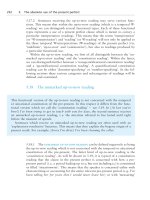
Figure 6.1: Battery of Planté cells arranged for high-voltage experiments.
From Guston Planté Recherches sur l’électricité, Paris 1883, p. 97.
ELECTRICITY
355
Institution. He took detailed notes, bound them, and sent them to Davy asking
for work in any scientific capacity. There was no work available at the time,
but later, when Davy was looking for a laboratory assistant, he remembered
Faraday and gave him the post. From 1813 to 1815, Davy was travelling in
Europe, and Faraday accompanied him as his assistant, meeting many of the
leading scientists of his day and becoming familiar with their work.
Faraday’s early scientific work was in chemistry. He conducted research into
the properties of steels of different compositions, and also into optical glass.
This work was paid for by sponsors (the finances of the Royal Institution were
such that sponsored research was essential to keep the Institution solvent). His
chief interest, however, was electricity and he was intrigued by Oersted’s
discovery that a compass needle could be deflected by an electric current. H.C.
Oersted was Professor of Physics at the University of Copenhagen. The
significance of his discovery was that it demonstrated a link, which had long
been suspected, between electricity and magnetism.
In 1821, Faraday was invited to write a historical account of electromagnetism
for the Annals of Philosophy. While preparing the article he repeated all the important
experiments and he became convinced that it ought to be possible to produce
continuous circular motion by using the circular magnetic force around a current-
carrying wire. Success came in September 1821 when he made two devices which,
with a little imagination, may be called the first electric motors. Both devices had a
basin filled with mercury. In one a bar magnet was fixed vertically and a loosely
suspended wire was hung from a point above the bar magnet so that it dipped into
the mercury. When a current was passed through the wire (and through the
mercury), the wire moved in a circular path around the magnet. In the second
device the wire was fixed centrally and the magnet (which floats in mercury) had
one end tied to the bottom of the basin. When a current flowed in the wire then
the magnet moved in a circular path around it.
Oersted’s experiment had shown that an electric current produced
magnetism. The question in Faraday’s mind was, could magnetism be made to
produce electricity? It was not until the autumn of 1831 that he had time to
pursue the matter properly, but he then succeeded in establishing the principles
that relate electricity and magnetism in a series of three crucial experiments.
The first was carried out on 29 August 1831. He had made a soft iron ring
about 2cm (1in) thick and 15cm (6in) in diameter and wound two coils on the
ring. Since the only wire available to him was bare metal, he insulated the
turns by winding a layer of calico under each layer of wire and a piece of string
between adjacent turns. The two coils were in several parts, so that he could
change the effective number of turns. He drew the arrangement in his
notebook, calling the coils A and B, and noted:
Charged a battery of 10 pr. plates 4 inches [10cm] square. Made the coil on B
side one coil and connected its extremities by a copper wire passing to a distance
PART TWO: POWER AND ENGINEERING
356
and just over a magnetic needle (3 feet [91 cm] from iron ring). Then connected
the ends of the pieces on A side with battery. Immediately a sensible effect on
needle. It oscillated & settled at last in original position. On breaking connection
of A side with Battery again a disturbance of the needle.
Faraday then showed that the iron ring was not essential—he could produce the
effect with two coils wound on a tube of cardboard. He also studied the effect
of changing the number of turns in the coils, and showed that the deflection of
the needle varied.
The experiment without the iron core was virtually the same as one he had
tried some years earlier, without success. Why had he failed then? The
important difference was that his understanding of what he was looking for had
changed. He had originally expected the mere presence of current in one wire to
produce an effect in the other, but by 1831 he was expecting another factor to be
involved. That additional factor was motion, or change. He expected an effect at
the moment he completed, or broke, the battery circuit, and because he was
looking for a transient effect he found it. His experiments continued with a
variety of coils, magnets and pieces of iron. On 24 September 1831 he described
an arrangement with two bar magnets and a piece of soft iron arranged in a
triangle. A coil connected to a galvanometer was wound on the soft iron, and he
found that when the magnets were pulled away the galvanometer recorded a
brief current in the coil. Faraday noted: ‘here distinct conversion of magnetism
into electricity’. He then arranged to use the most powerful magnet in London,
which belonged to the Royal Society. On 29 October 1831 he rotated a copper
disc between the poles of this magnet, and showed with his galvanometer that a
current was produced between the axis and the edge of the disc.
That arrangement of disc and magnet was the first generator, in the sense of
a machine which rotates conductors and magnets relative to one another and
produces electricity. Faraday himself seems not to have developed the idea
further. His next research interests were to show that the ‘magneto-electricity’
produced in his experiments was indeed the same electricity as that produced
by chemical cells, by frictional machines and also by electric fish. Having
satisfied himself on that he went on to study electro-chemistry.
GENERATORS
Faraday’s demonstration that electricity could be produced mechanically was
followed up by the Parisian instrument maker Hippolyte Pixii, who was closely
associated with the Academy of Sciences in Paris. Pixii realized that the output of
Faraday’s machine was limited because only one conductor—the radius of the
disc—was passing through the magnetic field at any one time. He made an
arrangement with two horseshoes end to end with their poles nearly touching.
ELECTRICITY
357
One was a permanent magnet and the other a piece of soft iron with a coil
wound on it. The soft iron was fixed and the permanent magnet rotated about
its axis by a handle and gearing. As it turned it magnetized the soft iron, first in
one direction then in the other, and at each change of the direction of
magnetization a current was induced in the coil. The resulting current alternated
to and fro, but at that time no one could conceive of any use for alternating
current. At the suggestion of Ampère, Pixii fitted a rocking switch, operated by a
cam on the axis, which reversed the connections to the coil at each half turn of
the magnet (see Figure 6.2). The output current was then uni-directional, and
Pixii showed that electricity from his machine could do the things that physicists
were then doing with electricity from other sources. Pixii made a number of
similar machines, which were sold with a printed leaflet describing experiments
that could be done; though only two of his machines survive.
Other scientific instrument makers were soon making similar machines, and
many designs appeared during the 1830s. See for example Figure 6.3. William
Sturgeon invented the metal commutator, used ever since on most rotating
electrical machines in place of Pixii’s rocking switch.
The first attempt to use these ‘magneto-electric machines’ (soon shortened to
‘magnetos’) for practical purposes was in the telegraph. The first practical electric
telegraph was installed by Cooke and Wheatstone in 1838, and in 1840 Wheatstone
was using a magneto for a new telegraph he was developing (see p. 714).
Figure 6.2: Hand turned magneto-electric generator made by Pixii in 1832 or
shortly after.
PART TWO: POWER AND ENGINEERING
358
In the 1840s a Birmingham chemist, J.S.Woolrich, and the firm of Elkingtons
used a large magneto for electroplating (see Figure 6.4), and in 1852 the first
electric lighting company was formed. This was the Anglo-French Société de
l’Alliance which intended to use magnetos to electrolyse water, yielding
hydrogen which would then be used in a limelight. That was not successful, but
in 1857 an electric arc lamp (see p. 362) supplied from a magneto weighing two
tonnes was demonstrated in a lighthouse. At the request of Trinity House,
Faraday supervised the demonstrations, which took place at Blackwall, and was
very pleased with the results. The machine was made by F.H. Holmes, who then
received an order for two machines for the South Foreland lighthouse. These
were working in December 1858, and several more machines were installed in
other lighthouses in subsequent years.
The output of a magneto is limited by the strength of the permanent
magnets, and until that limitation could be overcome there could be no
Figure 6.3: Magneto-electric generator by Saxton, 1833. Note that no wires come
from this machine. It was used simply to demonstrate that rotating a coil in front
of a magnet could generate electricity, which appeared as a spark when the
circuit was broken as the contact strip at the end of the shaft came out of
mercury in the small cup mounted on a pillar.
ELECTRICITY
359
large-scale generation of electricity. In 1845, Wheatstone and Cooke
patented the idea of using an electromagnet, supplied from a battery, in place
of the permanent magnet in a magneto for a telegraph. That was a step in
the right direction, and other people later made machines in which a
magneto supplied electricity to energize an electromagnet on another
machine which then gave a considerably higher current output. The real
answer to the problem, however, was the self-excited generator in which the
current for the electromagnet is supplied from the output of the machine
itself. Several people made such machines in 1866. One of them,
C.W.Siemens, expressed their advantage succinctly: ‘it is thus possible to
produce mechanically the most powerful electrical effects without the aid of
steel magnets.’
With its prospect of virtually unlimited electricity, the invention of the self-
excited generator stimulated electrical developments generally. The idea of the
Figure 6.5: An ‘A’ pattern Gramme generator, as used for small lighting
installations in the 1870s.
PART TWO: POWER AND ENGINEERING
360
electric arc light was well known, though until practical generators were
available there had been little encouragement to develop it. The first large-scale
manufacturer of practical generators was the Belgian engineer Z.T.Gramme
who worked in Paris. His machines used the ring armature, known ever since
as the Gramme ring, although similar armatures had been used earlier. This
had a toroid of iron wrapped round with a number of coils all connected in
series (see Figure 6.5). Many of these machines were sold from the 1870s,
mainly for arc lighting.
The first British generator manufacturer was R.E.B.Crompton. After
serving in the Indian army for some years he had returned to England and
bought a partnership in an agricultural and general engineering firm at
Chelmsford, in Essex. He intended to pursue a longstanding interest in steam
transport, but found himself involved in electric lighting. Crompton designed a
new foundry for relatives who owned an ironworks and sought lighting
equipment so that it could be worked day and night. He visited Paris and
bought some of Gramme’s equipment for the ironworks, then realized there
was a market for electric lighting apparatus in Britain. Initially he imported
equipment from Gramme and others in Paris, but soon decided that he could
improve upon it, and he began manufacturing his own.
The first generators Crompton made were based on the designs of the Swiss
engineer Emile Bürgin (see Figure 6.6). Burgin had improved on Gramme’s
Figure 6.5: An ‘A’ pattern Gramme generator, as used for small lighting
installations in the 1870s.
ELECTRICITY
361
machines by using a series of iron rings for the armature, arranged in parallel
along the axis, where Gramme had used a single ring. This led to a much
stronger construction, and one which was easier to cool than Gramme’s because
there were plenty of air passages through the armature coils. Crompton made
many detailed improvements in the mechanical design of generators, and jointly
with Gisbert Kapp he patented the compound field winding in 1882.
The output voltage of early generators varied considerably with the load.
As the load increased the voltage would fall, and, if the load were shed
suddenly (possibly as a result of a fault) the voltage would surge. This did not
matter when the load was arc lighting, but with filament lamps (see p. 365) it
was critical. Compound winding sought to overcome this problem: the field
magnet had two sets of windings, one carrying the main magnetizing current
and the other carrying the load current. The second, compounding, winding
would boost the magnetic field as the load current increased, thus increasing
the output voltage. Another benefit of compound winding was that the
magnetic field of the extra coils compensated for the distortion of the magnetic
field caused by the current in the armature. In the simple generator, without
compounding, the brush position had to be varied as the load changed, to
avoid excessive sparking and consequent wear of the commutator and brushes.
Compounding resulted in a machine that did not need such constant attention.
During the 1880s generator design gradually became a science rather than
an art. Gisbert Kapp, who had worked for Crompton but later became the first
Professor of Electrical Engineering at the University of Birmingham, sought to
design machines mathematically, while Crompton said that he always designed
Figure 6.6: Crompton-Burgin generator of about 1880.