An Encyclopedia of the History of Technology part 41 pptx
Bạn đang xem bản rút gọn của tài liệu. Xem và tải ngay bản đầy đủ của tài liệu tại đây (99.97 KB, 10 trang )
PART TWO: POWER AND ENGINEERING
382
The first company to exploit electric motors on a large scale was Siemens,
and their first major customer was the Prussian state mines. Electricity in
mining, however, developed fairly slowly. Although some mine winders were
electric before the First World War it was only in the 1920s that mine
electrification became widespread. A major industrial use of electric power was
the iron and steel industry. Several ironworks adopted electric lighting quickly
because it facilitated all-night working, so perhaps ironmasters were easily
alerted to the possibilities of the new power. Electric motors proved to be very
good for driving rolling mills, where the combination of power and precise
control was valuable. Thereafter electric motors were gradually introduced for
driving machine tools, and the advantages of individual drives over line-shaft
systems were readily appreciated.
The first permanent public electric railway was opened at Lichterfelde in
Germany in 1881. Built by Siemens, it ran for about three kilometres. Each
carriage had a motor under the floor connected to the wheels through a belt
drive. The first electric railway in the United Kingdom ran between Portrush
and Bushmills, in Ireland. Electric traction was chosen there because abundant
water power was available and a hydro-electric generating station was built on
the River Bush. England’s first electric railway was the Volk’s Railway which
still runs on the sea front at Brighton.
The railways just mentioned were all small systems. The first really
practical electric tramway system was built by Sprague in Richmond, Virginia,
in 1888. Forty cars powered from overhead conductors ran over 20km (12.5
miles) of streets. Frank J.Sprague trained as an engineer with the US navy,
then set up his own electrical engineering company in 1884. His most
important contribution was the multiple unit control system, which made it
possible to have motors distributed along the length of a train and supplied
from current collectors on each coach but all controlled from the driver’s cab.
He also introduced the motorized bogie construction in which one end of the
motor is pivoted on an axle and the other supported on springs.
Electric trams were introduced only slowly in Britain, partly because the
established horse-drawn tramways were approaching the date when, under the
Tramways Act, they could be purchased compulsorily by the local authorities.
New tramways after 1890 were virtually all electric.
Deep tube railways in London and other cities only became practicable with
electric traction. The first was the City and South London Railway which ran
initially from Stockwell to the Bank. The original rolling stock was fourteen
locomotives each of which could haul three carriages with thirty-four passengers
in each. Five million passengers were carried in the first year. Electricity was
generated in a specially built power station at Stockwell, and supplied through a
third rail. The service interval at periods was just under four minutes.
Most early electric traction systems used direct current because the DC
series wound motor has good operating characteristics for the purpose. In
ELECTRICITY
383
1920 the Ministry of Transport adopted 1500 volts DC as the standard for
main line railways. Technical advance soon forced a change in the standard,
however. The introduction of the mercury arc rectifier in 1928 made it possible
to transmit AC and convert to DC on the train; most of British Rail now uses
this system, with 25kV overhead lines. Since about 1960 semiconductor
rectifiers have been available for high powers, and are replacing the mercury
arc rectifiers. The Southern Region, where the traffic density is higher than in
most of the country, uses a third rail for the conductor and operates at about
700 volts DC. Other countries have used a variety of systems and frequencies.
Switzerland and Italy have some three-phase railways, with one phase earthed
to the running rails and the other two phases connected through two overhead
wire systems.
The advantages of alternating current transmission encouraged
engineers to develop AC motors. Most DC motors will in fact operate on
AC supplies, provided that the iron cores in their fields are laminated, but
they are not so efficient. Such machines are called universal motors, and
are often found in small domestic appliances such as vacuum cleaners and
food mixers.
The first practical AC motors were developed by Nicola Tesla in 1888.
He was born in Austria-Hungary but in 1884 emigrated to the USA where
he spent most of his life. He worked for a time for Edison, the leading
exponent of DC systems in the USA, then joined Westinghouse, the
leading AC man.
In his machines Tesla made use of the fact, discovered by Arago in 1824,
that a piece of magnetic material free to turn will follow a rotating magnetic
field. He created a rotating magnetic field by using two coils energized from
supplies that were in synchronism but not in phase. His first machine had two
coils with axes at 90° to each other supplied with alternating currents also 90°
out of phase. He showed that the resultant of the two oscillating magnetic
fields was a rotating field, and he performed the same analysis for a three-
phase system at 120°. Tesla’s first motor was a synchronous one—that it, the
rotating member either was or became a permanent magnet, and its poles
followed the rotating field round, keeping in synchronism. He also made
induction motors, in which the rotating member is not a permanent magnet
and turns at a speed slightly lower than the speed of the rotating field.
Currents are then induced in the rotor and these interact with the rotating field
to provide the driving force.
Other people were also working on the idea of a motor driven by a rotating
magnetic field, and Tesla’s patent claims were challenged in the US courts, but
his claims were upheld. He also showed that an induction or synchronous
motor can be run from a single phase supply if part of the field winding is
connected through a capacitor or inductor to give a second phase. Once
started, such a motor will run satisfactorily on a single phase supply. The
PART TWO: POWER AND ENGINEERING
384
Westinghouse company bought Tesla’s patents, and from 1892 they were
manufacturing AC motors and promoting AC supply systems.
In the twentieth century most of the world’s electric motor power comes
from induction motors. Their disadvantage is that they are essentially constant
speed machines, but for many applications that is perfectly satisfactory and the
inherent simplicity and robustness of induction motors, which usually have no
brush gear, make them the first choice for many applications. Most domestic
washing machines are driven by an induction motor with capacitor start.
A motor that is sometimes confused with the induction motor is the
repulsion motor, developed by Elihu Thomson and Professor J.A.Fleming.
Fleming, better known for his work on radio, studied the forces between
conductors carrying alternating currents. In 1884 he showed that a coil
carrying alternating current tries to position itself edge on to a magnetic field,
and the force produced in this way provides the basis for the repulsion motor.
A typical repulsion motor has a single field coil connected to the supply and a
wound multi-coil armature with commutator. Two brushes on opposite sides of
the commutator are connected together (but not to the supply) and short
circuit the armature coils which at that instant are across the magnetic field.
There is then a turning force which moves the armature. Repulsion motors
have been used for electric traction. They have a good starting torque and
some speed control is possible by moving the brushes.
MODERN ELECTRIC MOTORS
By the mid-twentieth century it seemed reasonable to say that electric motor
development was complete, but in 1957 Professor G.H.Rawcliffe developed the
pole amplitude modulated, or PAM, motor. This is a synchronous or induction
motor whose field coils are so arranged that by interchanging a few
connections the number of poles can be changed. Since the speed is
determined by the number of poles (as well as by the supply frequency) this
gave a motor whose speed could be switched between two distinct values. A
PAM induction motor therefore retains the reliability and robustness of the
conventional induction motor but can work at two different speeds.
The other approach to variable speed control is to change the supply
frequency. With power semiconductors that is becoming possible. By 1960
semi-conductor devices were available capable of controlling a few tens of
amperes, but progress in the following decade was so rapid that by the end of it
semi-conductor frequency convertors were available capable of supplying the
largest motors—and controlling their speed.
Another area of motor research that remains active is linear motors. Often
described as conventional motors that have been slit open and unrolled, linear
motors have been a subject of research at least since 1841, when Wheatstone
ELECTRICITY
385
made one. The idea was revived in 1901 when the Norwegian Kristian
Birkeland tried to use a linear motor as a silent gun. Their best-known modern
exponent is Professor Eric Laithwaite, who was first interested in them as a
means of driving a weaving shuttle. Linear motor research continues, and the
widespread application of these machines will probably use semiconductor
controls also.
THE STEAM TURBINE
In nearly all the early power stations the prime movers were reciprocating
steam engines. The technology was well established, and the electrical
designers made generators to be driven by the available steam engines even
though their rotational speed was less than ideal. Some stations used a belt
drive to increase the speed, though Willans and Belliss & Morcom high speed
engines were often directly coupled to the generator. The higher rotational
speed of the turbine made it the ideal prime mover for power stations.
Generators for use with turbines have usually only a single pair of field
poles, rather than the multi-polar machines used with reciprocating drives.
Initially the armature windings, in which the current was generated, were the
rotating member and the field poles were static. As machines became larger, it
became difficult to make brushes and slip rings or commutators adequate to
take the current. The solution was to ‘invert’ the machine, having the armature
static and the field rotating. The brushes then had to carry only the
magnetizing current for the field. The last large rotating armature machine was
a 1500kW set for Neptune Bank power station on Tyneside in 1901.
The first rotating field generators had salient poles built up on the rotor
shaft. The Anglo-Swiss engineer Charles Brown, of the Brown-Boveri
partnership, proposed that the rotor should be a single forging and that the
windings should be carried in slots milled in the surface. This basic design has
been used for large generators ever since.
The largest turbines and generators now used by the Central Electricity
Generating Board, serving England and Wales, are rated at 660MW. Today
the entire electricity demand of the United Kingdom could be supplied from
only one hundred generators.
ELECTRICITY TODAY
Modern life depends on electricity. Virtually every home in Britain is
connected to the public electricity supply, though that has been achieved only
since the Second World War. In 1920 the supply industry had under a million
customers in England and Wales. The figure reached 10 million by 1945 and
PART TWO: POWER AND ENGINEERING
386
15 million by 1960. Now there are 21 million, and they use about two
hundred thousand million units of electricity per year. Of this consumption 36
per cent is used at home, 38 per cent in industry, 22 per cent in commerce, and
the remaining 4 per cent in such diverse applications as farming, transport and
street lighting. Of the domestic electricity, 21 per cent is used for space heating,
18 per cent for water heating, 11 per cent for cooking and 17 per cent for
freezing and refrigeration. Everything else, including lighting, comes out of the
remaining 33 per cent.
At first electricity was only for the well-to-do. The major expansion came
during the 1920s and 1930s, and during that period the average consumption
per household fell, reflecting the fact that new consumers used electricity
mainly for lighting, and not much for other purposes. The range of domestic
electrical appliances with which we are familiar today have in fact been
available almost from the beginning. Catalogues of the 1890s include electric
cookers, kettles, saucepans, irons and fires. Early electric fires used carbon
filament lamps as the heating member because there was no metal (except
platinum) which could be heated to red heat in air without oxidizing. A great
advance came in 1906 with the alloy nichrome, a mixture of nickel and
chromium. This does not oxidize when red hot, and most electric fires since
that date have used nichrome wire elements on fireclay supports.
Storage heaters for room heating were introduced on a small scale in the
1930s. In the 1960s the Electricity Council conducted research to improve
their design, seeking longer heat retention, and modern storage heaters are
much smaller than their earlier counterparts.
Motorized appliances generally came later than lighting and heating, though
an electric table fan was on sale by 1891. The first electric vacuum cleaner was
made in 1904. Early electric washing machines had a motor fixed underneath
the tub. Usually there was a mangle fitted on top (spin driers came later) and a
gearbox that permitted the user to couple the motor either to the agitator in the
tub or to the mangle. Food mixers and refrigerators came after the First World
War, though they were rare until the 1950s (see Chapter 19).
Electric space heating and refrigerators have changed house design. Before
the mid-1930s it was normal to have a fireplace in every bedroom, and into the
1950s every house was built with a larder. Many modern houses have no fire-
place, except possibly one in the living-room for effect. Larders have become
obsolete since it is assumed that food which might go bad will be kept in the
refrigerator.
Lighting has also progressed. The carbon filament lamps that were such a
wonder in the 1880s and 1890s encouraged the gas industry to develop the
mantle, and for a time gas lighting undoubtedly had the edge over electricity.
The electric lighting industry sought a better filament material. Three metals
seemed promising: osmium, tantalum and tungsten. Osmium filament lamps
were on sale from 1899, but since 1909 all metal filament lamps have used
ELECTRICITY
387
tungsten. Carbon lamps continued to be made for some years since they were
cheaper in first cost, but the metal filament lamps were more efficient, giving
cheaper light when the cost of electricity was taken into account. The latest
development in high-power filament lamps is the inclusion of a halogen gas
(usually bromine or iodine). This reacts chemically with tungsten that
evaporates from the filament and is deposited on the glass. The resulting
tungsten halide is a gas which decomposes close to the hot filament, depositing
the tungsten back on to the filament. Such lamps can be run at a higher
temperature and are therefore more efficient.
Various gas discharge lamps were made in the 1890s, and neon lamps were
introduced about 1910. The widespread use of both mercury and sodium
discharge lamps dates from the 1930s. The low pressure sodium lamp, with its
extremely monochromatic yellow light, has been popular for street lighting
because it is the most efficient of all. Since the early 1970s, however, the high
pressure sodium lamp has been taking over. It is almost as efficient, and
although its light has a yellow-pink tinge its colour rendering ability is fairly
good.
Fluorescent lamps, developed in Britain just before the Second World War,
have an efficiency in between that of filament lamps and discharge lamps. A
low pressure mercury discharge within them produces ultra-violet light which
acts on the fluorescent coating of the tube to give visible light. The choice of
phosphor determines the colour and the efficiency of the lamp, and they are
widely used in commercial applications.
One great advantage of electricity is its easy controllability, and with time-
switches, thermostats and semi-conductor dimmers that is even more true than
before. Other technologies have done much for mankind: electricity has put
virtually unlimited power at the disposal of all.
388
7
ENGINEERING, METHODS
OF MANUFACTURE AND
PRODUCTION
A.K.CORRY
INTRODUCTION
‘Man is a tool using animal’ said Thomas Carlyle but, additionally and more
significantly, man has progressively designed and made tools for use in
meeting his developing needs and adapted his techniques and social
organization to make the best use of his skills of mind and body in
manipulating materials to his advantage. Side by side with the development of
hand tools the principles of work organization were being realized in tribal
cultures by making the best use of the special skills of individuals in making
and maintaining tools for the experts using them: the relationship between
hunter and spearmaker is an example of this division of labour. Progressively it
was also recognized that there exist three basic elements in tool design. The
first of these, the need for a cutting edge harder than the material to be
worked, is the most fundamental and delayed wider development until the
discovery of metals. The other two factors (which are also dependent to an
extent on cutting tool materials) are the need to minimize demands on human
energy and the search for substitutes for manual skill; all three are the subject
of research and development to this day.
BRONZE AND IRON AGE TOOLS
It is probable that bronze was the first metal used as a tool material although iron
was known about at an early date. There are many references to iron in the
Bible and its superiority to bronze. Goliath is described as wearing bronze
ENGINEERING AND PRODUCTION
389
armour and having a spear pointed with iron, and there are also mentions of
steel. Aeschylus, c. 480 BC, writes about the superiority of iron for weapons.
The greater difficulty of extracting and forging iron, and the effect of corrosion,
extended the use of bronze in weapons, armour and tools until the techniques of
working iron were developed to demonstrate its superior qualities in providing
and keeping a keen cutting edge. By the end of the Roman Empire virtually all
the forms of modern hand tools had been devised; the second major step in the
development of manufacturing was already under way by the introduction of
mechanical means of enhancing the force of cutting and forming to take
advantage of the high cutting speed possible with iron tools.
The first mechanically assisted cutting operation was drilling and the
earliest example is the rocking drill, the most important method being the cord
drive whereby an assistant manipulates a cord wrapped round the vertical drill
spindle to give it an alternating rotary movement. This system, applied
horizontally, was probably used to drive the lathe spindle which produced the
first extant example of turning: an Etruscan wooden bowl found in the Tomb
of the Warrior at Corneto, c. 700 BC. The earliest illustration of this type of
lathe, on a wall of the Egyptian tomb of Petosiris (third century BC), shows an
assistant holding each end of the cord to give the rotational movement to the
spindle. The Egyptian figurative convention confusingly shows the spindle
vertical, but it illustrates the provision of bearings and tool rest for accurate
positioning of the cut being made and to take the load imposed on the
workpiece by the cutting action. These requirements, for load bearing and tool
rigidity in relation to the workpiece, have continued to be principal elements in
machine tool design, together with work holding and spindle drives.
The Kimmeridge ‘pennies’ discovered at the Glastonbury Lake Village,
Somerset, were turned from soft stone c. 100 BC and show interesting methods
of attaching and driving the workpiece from the spindle. One has a roughly
drilled hole used to mount the work on a shaft or mandrel which in turn is
held between centres similar to the Egyptian lathe. Others show the use of a
squared hole to permit driving from a similarly squared spindle nose and the
small centre holes necessary for head and tail centring. Spindle driving
methods advanced slowly. Although the ability to turn in stone led to the
spindle-mounted grindstone with a turned true outer surface, for maintaining
cutting edges on tools and weapons, the cranked arm used for driving the
wheel in the earliest illustration of it on the Utrecht Psalter, AD 850, was not
used for a lathe spindle until the second half of the fifteenth century. Similarly
the bow replacement for the cord drive operated by an assistant was not used
for lathe drive until the Roman Empire. This method is still used in the Middle
East by wood turners and watchmakers in the Western world were using bow
drills in the early part of this century. The difficulty of manipulating the bow
while guiding the tool with intermittent cutting, calls for a very high degree of
manual skill and dexterity and it is only possible to make light cuts.
PART TWO: POWER AND ENGINEERING
390
EARLY MACHINES
As the size and complexity of work for the lathe increased so did the need for
increased rigidity and more power, which was met by heavier construction of
the wooden frames of lathes and the development of the pole lathe. This still
gave intermittent cutting, but freed the turner’s hand to concentrate on guiding
the tool by the use of a spring pole to which one end of the cord was attached
and the other end to a foot operated treadle after passing round the work to be
turned. When the treadle was pressed the work revolved towards the turner
for cutting, and on completion of the treadle throw the spring pole returns the
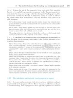
work. This type of drive probably existed in the twelfth century; the best early
illustration of the pole lathe occurs in the Bible Moralisée, c. 1250 (see Figure
7.1). The use of this type of lathe has continued in similar form until well into
the twentieth century with the ‘chair bodgers’ at work in the woods around
High Wycombe in Buckinghamshire.
The pole lathe, with its intermittent cut, was not adequate for turning metal
and, as the need for machined metal products increased, the continuous
method of driving was developed, first of all through the use of a large wheel
in separate bearings carrying round its periphery a cord which also passed
round the work spindle. The large wheel was turned by an assistant using a
cranked arm, first illustrated c. 1475 and also in Jost Amman’s Panoplia of c.
1568. The next method of continuous driving using a treadle and crankshaft,
shown by Leonardo da Vinci, c. 1500, in the Codice Atlantico and developed by
Spaichel, c. 1561, still gives a satisfactory system for the ornamental turners,
sewing machines and other machines where only human power is available;
Figure 7.1: Miniature painting of a pole lathe, c. 1250, from the Bible Moralisée.
ENGINEERING AND PRODUCTION
391
but it was the large wheel and continuous band method which was to enable
the use of other power sources: horse gins, water wheel, steam engine and
electric motor.
The development of continuous drive also made possible the control of the
cutting tool relative to the work through systems of gears, screws and guides
progressively to eliminate the skill required in holding and guiding the cutting
tool and make use of the ideas first expressed according to drawings in the
Mittelalterliche Hausbuch, c. 1480, of tool holder and cross slide with screw
cutting lathe.
MEASUREMENT
From the earliest days of man’s use of tools, measurement of the size and shape
of things produced has been of prime importance to satisfy the performance
required. The earliest standards were those designed to meet individual needs,
but these were gradually developed to use units of measurement which could
be employed to reproduce articles in a range of sizes. The first ‘standard’ was
the Egyptian Royal Cubit, equivalent to the Pharaoh’s forearm length plus
palm and made of black granite. This master standard was subdivided into
finger widths, palm, hand, large and small spans, one remen (20 finger widths)
and one small cubit, which was equivalent to six palms. The small cubit was
used for general purposes and made in granite or wood for working standards.
These were regularly checked against the master, and many Egyptian temples
and other buildings had reference measures cut into walls to check the wooden
cubit which, being much easier to handle than stone although more prone to
variation, came into more general use. These principles and the use of cubits
and their subdivisions became the basis of Roman, Greek and Middle Eastern
measures and later European measures, although the actual ‘reference factor’,
the forearm, produced some alternative cubits in different parts of the world.
All these standards were ‘line standards’ involving measuring between
engraved lines and this remained the basis of national and international
standards until 1960, when the concept of keeping a physical standard was
abandoned in favour of the wavelength of krypton 86 which is a readily
reproducible and constant reference factor.
Once standards of length were established, these were used to check parts
for accuracy and measuring tools, for use in transferring sizes for comparison
with the standard, were developed. Calipers, dividers and proportional
dividers were evolved by Greeks and Romans some 3000 years ago. These
instruments, with the cubit measuring stick, made possible accurate
calculations, by measuring the shadow cast by the sun, to determine heights of
buildings, agree the time of day, establish the calendar and navigate by
reference to the stars. From this point the development of metrology has been