Hướng dẫn sử dụng Coreldraw x5 - part 15 potx
Bạn đang xem bản rút gọn của tài liệu. Xem và tải ngay bản đầy đủ của tài liệu tại đây (983.91 KB, 10 trang )
3. Let’s say you’re not thrilled with the From and To colors in the fountain fill. To change
a color, while the Interactive Fill tool is still selected and you can still see the control
handles for the fill above the gear drawing, click the tiny From color marker—it’s
marked with the color you chose in the previous tutorial. Now the color is highlighted
and available for editing. Click a light gray color well on the Color Palette. Then click
the To color marker and click a medium to dark gray color well on the Color Palette.
If you’re careful, you can drag a color well color and drop it on the selected From
and To color markers above the object to recolor them.
4. Now let’s say that the color transition between From and To in the fountain fill isn’t
dramatic enough, but you do like the two colors. Adjust the midpoint of the fill by
dragging on the midpoint control, shown in Figure 5-3. You drag it toward the From
color marker to emphasize the To color in the fill, and vice versa.
124 CorelDRAW X5 The Official Guide
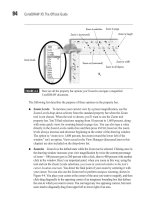
FIGURE 5-3 Use the Interactive Fill tool to embellish your illustration.
Color Palette
Midpoint control
Color well
Click to make the To
color subject to editing.
Click-drag
5. The “D” gear is looking terrific now, and it’s going to look more terrific by the end
of the chapter. To quickly add the same sort of fill to the “G” gear, choose the
Attributes Eyedropper tool from the toolbox. Click over the D gear to sample its
properties, and then click over the G gear to apply the sampled properties, as shown
next—occasionally, you luck out in Life, and some things are simple… Press
CTRL+S to save your work up to this point. In fact, just make it a practice to save
your work every 10 minutes or so; it’s only two keystrokes.
Ill 5-7
With the exception of the Text tool, pressing the SPACEBAR toggles your current tool
to the Pick tool; a second press of the
SPACEBAR toggles you back to the last tool
you were using.
Going 3D
Although CorelDRAW is a drawing program and not a modeling application such as
Autodesk 3D Studio, you can indeed get dimensional effects with the Extrude tool to make a
simple drawing such as this logo pop off the page…or off a T-shirt. The following sections
take you through a basic and then an advanced editing technique that will make your
audience wonder how on earth you accomplished this logo by reading one chapter in a
book!
Using the Interactive Extrude Tool
The Interactive Extrude tool is a basic tool for defining edges that appear to extend into the
third dimension of space, adding depth to the height and width of the object to which you
apply this tool. However, once you’ve added depth to a selected object, it might not be
apparent to you or your audience that this is a 3D shape because of the way it’s “posed” on
the drawing page. By default, the Interactive Extrude tool creates edges that appear mostly
behind the extruded shape, because of an optical principle known as a vanishing point.
CHAPTER 5: The X5 Test Drive 125
5
A vanishing point (tell your friends you know that da Vinci discovered vanishing points) is
the point in 3D space where, if you drew lines marking the angles of an object with depth,
the lines would converge. You see vanishing points all the time: say you’re standing on train
tracks (when a train isn’t coming), and you look straight down the tracks. Where the rails
converge is the vanishing point.
Similarly, to get the most out of the Extrude feature in CorelDRAW, you want to view an
extruded shape off-axis, not straight-on, because looking at objects directly face-front
removes the perspective from the object, flattening its appearance. CorelDRAW has
additional features after you’ve made a shape into an extruded shape, one of which is a
rotation feature—yes, you can rotate a 3D object on your drawing page—to show off all
three possible facing sides of the extruded shape. An object viewed in ¾ view shows off the
most visual detail (this is why portrait photographers try to get customers to point their head
off-camera), and the following tutorial takes you through object extruding, rotating, and how
to interactively adjust the depth of the object you extrude.
Extruded sides of an object by default inherit the fill from the parent object.
Therefore, because the gear in this example has a fountain fill, so do the objects
that make up the sides of the gear. Fountain fills aren’t as visible when they’re on
the 3D face of a shape that has lighting, which you’ll add in this tutorial. However,
you can modify the fill of the control object (the shape you started with), the
extrude:
CTRL-click to select it from the group of shapes that dynamically make
up the extruded object, and then modify the fill.
Making a Logo into a 3D Logo
1. With the D gear selected on the drawing page, click-hold the Effects group button
( just above the familiar-shaped Eyedropper tool) on the toolbox to reveal the flyout
that has the Extrude tool. Select the Extrude tool from the flyout.
2. Click-drag just a little, straight down on the object, as shown in Figure 5-4. Just a
little does the trick—you’re establishing an extruded object and setting a vanishing
point for the object at the same time. Stop dragging when one of the sides of the
extrude object is visible. Resist the temptation that accompanies the natural thought,
“the more I click-drag, the more extruded the gear will be.” Nope—the more you
drag, the farther the vanishing point is defined relative to the object, and it’s very
easy to set the vanishing point clear off the page, and possibly extend it to the
Theophilus crater on the moon.
Double-click the extrude group of objects while the vanishing point and other
onscreen indicators are visible. You’re now in a mode where you can rotate the
extrude objects onscreen in three dimensions. If you deselected the shape, double-
click an extrude area, and then single-click (this can be done with the Extrude or the
Pick tool). Point the D gear a little upwards by click-dragging up and just a little to
126 CorelDRAW X5 The Official Guide
the left on the face of the object, as Figure 5-5 shows. The goal here is to create a
visually dynamic logo that the audience is intimidated by, so the audience is looking
up at this goliath of a company (yeah, yeah, it’s trite, but it works). If necessary,
drag one of the markers along the green ring encircling the D gear to rotate the
object parallel to the screen; think of the ticks on a clock face, and you’re rotating
the D gear from 9 to 8 o’clock, for example.
3. Click-drag the marker shown in the following illustration toward the gear to
decrease its depth. Dragging it away from the gear makes it deeper, and although
this is illuminating advice, you will probably never need to make an extruded shape
fatter. Also note that the vanishing-point line, the light blue dotted line, extends way
off the page. This is of absolutely no consequence in your design work. The vanishing
point does not print, and if your gear illustration looks fine right now, it is fine,
regardless of onscreen guides.
Ill 5-8
CHAPTER 5: The X5 Test Drive 127
5
FIGURE 5-4 The Extrude tool is used to set a third dimension for your object. Other features
help you set an angle of rotation and the depth of the object.
Extrude tool
Click-drag just a little.
Drag toward object
to decrease depth.
At any time in the future, you can change the rotation of the extruded shape, as well
as the depth—it’s a dynamically editable object. To quickly display the property bar
options and the depth control marker on the object, and switch to the Interactive
Extrude tool, you can double-click the object with the Pick tool.
Adding Lighting and a Bevel
Let’s polish the D gear part of the logo now; the G gear can take on the same look as the D
once it’s completed by copying its properties to the G. The Extrusion Lighting feature is
available only when an object is extruded and is located on the property bar—it’s the light
bulb button. Lighting can be performed using one or up to three individual lights, and each
light can occupy one of 16 possible positions around the object.
As an embellishment, you’ll add a very small bevel edge to the front face of the D gear,
just to add a little highlight to the edge where the extrude and the object meet. Realistically,
industrial gears don’t often have beveled edges, but they also aren’t shaped in alphanumeric
characters! This is Art and not a blueprint.
Here’s how to add lighting and the bevel edge to the D gear.
Finessing the Look of the Gear
1. With the D gear selected, right-click the No Fill color well on the Color Palette to
remove the outlines. The extruded gear will take on a washed-out look, but you’re
not done yet.
2. Click the Extrusion Lighting button on the property bar.
128 CorelDRAW X5 The Official Guide
FIGURE 5-5 Use the Extrude Rotation feature onscreen to make the gear truly three-
dimensional in appearance.
Depth control
Drag on face to rotate up, down, left, and right.
Drag to rotate parallel to screen
Vanishing point
3. Click the marker labeled “1” to add lighting to the extruded object.
4. Drag the “1” light to the front right position on the lighting cage surrounding the
proxy sphere shape.
5. Click the Extrusion Bevels button, the cube with the “X” through its front.
6. Check the Use Bevel check box.
7. Put the cursor in the bevel height field and then type 0.07". Objects that feature
concave edges, as this gear shape does, do not take a bevel of a much larger
size…and still look recognizable.
8. Put the cursor in the bevel angle field, and then type 30.
9. Click anywhere in the document to apply the new bevel angle.
Ill 5-9
Because the light is facing the right side of the gear, the lighting on the gear’s teeth looks
superb and quite intricate in design. The face, conversely, looks a little dim because it’s
CHAPTER 5: The X5 Test Drive 129
5
facing away from Light 1. This is not a big design flaw; the face looks appropriate when
contrasted against its side, but if you want to lighten it:
1. Click the extrude group to select the group. Then CTRL-click the front face to select
it separately from the other objects.
2. Choose the Interactive Fill tool; the markers appear for the color stops of the Linear
fountain fill.
3. Click a color marker and then choose a different color well from the Color Palette by
clicking.
4. Alternatively, if you think a solid color would be better for the gear, deselect the gear
and then drag a color well on top of the face of the extruded object. The extruded
sides will take on this color. Press
CTRL+Z to undo if you prefer your original to your
changes.
The rotation properties of extruded objects follow the convention of 3D modeling
programs. The X axis (top to bottom rotation) runs left to right through the object,
the Y axis (rotation from left to right) runs top to bottom through the object, and the
Z axis runs around the object parallel to the page in angles of rotation like those of
an analog clock. Degrees of rotation are counterclockwise—negative values spin the
object in a clockwise direction.
Duplicating the Extrude Properties
When an extrude object is selected, a button is available on the property bar for duplicating
the properties of the extruded object to a plain, unextruded one: Copy Extrusion Properties.
This feature can change the angle and lighting of an existing extruded object, but that’s not
what you need to do right now. You want to get the G gear extruded at the same depth, with
the same lighting and bevel, but you then want to change its rotation so it’s facing away
from the D in a mirror-like fashion.
Not a big deal! Follow these steps.
Creating Another Gear with the Copy Extrusion
Properties Feature
1. Double-click the D gear’s extruded side using the Pick tool to bring up the features
on the property bar.
2. Move your cursor over to the G gear, and then click it to select it.
3. Click the Copy Extrusion Properties icon (shown next) on the property bar; because
the G object has an outline, the outline remains on all edges of all the objects. Not
what you had in mind for the finished art: right-click the No Fill color well on the
Color Palette to remove the outline.
130 CorelDRAW X5 The Official Guide
Ill 5-10
4. To precisely mirror the angle of the extruded G gear calls for a different feature than
the onscreen interactive rotation: click the Extrude Rotation button on the property
bar, the second from the left after the VP Locked To… button.
5. Click the Rotation Values button at the lower right of the “3” (shown next) to go to a
number-field view of the current object’s rotation.
6. To mirror the G gear from left to right is a Y axis rotation. Whatever value you see
in the Y field, replace it by typing in an equal negative value. In this example, the Y
aspect of the G gear (copied from the D gear) is –22, so typing in 22 rotates the G an
equal and opposite amount compared to the D gear.
Ill 5-11
CHAPTER 5: The X5 Test Drive 131
5
Extrude Rotation
Rotates from
left to right
Rotation values
7. Click the Extrusion Light button, and then drag Light 1 from its upper-right position
to the upper left. Artistically, it’s usually bad form to mix lighting sources in a single
illustration; however, this is a logo, with no real visual clue as to where the light is
shining because the scene is incomplete. You can get away with this in the world of
logos.
Ill 5-12
Adding Text to the Logo
You might call this assignment finished; you now have two stunning 3D oddly shaped gears
in the document. But this assignment is for a logo, not for an icon that really would serve an
advertising purpose only if it were painted on a shingle above a store in a hamlet in the 1600s.
You need text to accompany the graphic: a fancy artistic text title above the graphic will serve
the purpose of a logo quite well, and in smaller text Dyson Gears’ web address will lessen the
need of the viewing audience to ask the person wearing the T-shirt for contact info.
In the following sections, you’ll use another effect, the envelope feature, which can mold
a headline into any shape you can imagine, integrating into the overall design and catching
an equal amount of audience attention.
Creating an Envelope Shape
CorelDRAW’s Envelope feature is dynamic, just like Extrude and the Polygon tool, so you
can shape and reshape an object until you’re happy with the result. For this assignment, a
good visual reinforcement of the mirrored gears might be to take “Dyson Gears” and
reshape the name to look like a squared-off lozenge, larger in the middle than at either end.
To perform this Envelope maneuver, you’ll begin with a default Envelope shape and then
customize it so that its sides are straight and not curved.
132 CorelDRAW X5 The Official Guide
Making a Headline / Enveloping the Headline
1. Choose the Text tool from the toolbox.
2. Click an insertion point on the page, just above the gears.
3. Type in all caps (hold SHIFT): DYSON GEARS. Artistic text is editable as text, but
as far as the envelope effect goes, text is a malleable object, just like any object
you’d draw. It’s also by default 24 points in height and Arial, which is not an
exciting font. Select the text with the Pick tool, and then choose Futura XBlk BT
from the Font list; it should be toward the top of the list as all recently used
typefaces are ordered.
4. While holding SHIFT, drag a corner handle away from the text center until the text
width is a little narrower than the gears. Alternatively, you can type 60 in the Font
Size box to make the text 60 points in height, a little less than 1 inch; this trick is
useful, however, only if you’re familiar with how point size corresponds to inches.
See Figure 5-6.
5. One entry above the Extrude tool in the Interactive Tools group on the toolbox is the
Envelope tool; choose it and then select the text with your cursor. You’ll see a faint
dashed blue outline around the text now.
CHAPTER 5: The X5 Test Drive 133
5
FIGURE 5-6 Use the same font as you used for the gear letters to avoid typeface style clashes.
Drag and hold SHIFT
to scale from center.