Hướng dẫn sử dụng Coreldraw x5 - part 30 doc
Bạn đang xem bản rút gọn của tài liệu. Xem và tải ngay bản đầy đủ của tài liệu tại đây (911.94 KB, 10 trang )
Here’s what the Sprayer property bar options give you control over:
●
Object Spray Size/Scale These two options control the initial object size of the
sprayer style (the objects that make up a specific spray type) based on a scaled
percentage of the original spray object selected. When the Size/Scale options are
locked, you can set the scaling of successive objects to be increased or reduced in
scale relative to the size of the first object in the sprayer style.
●
Spray Order This option lets you set the ordering of the sprayer objects:
Randomly, Sequentially, or By Direction. If the sprayer style features only one
object to vary, changing this option has no effect. Try the mushrooms preset; the
Spray preset contains several different objects of different sizes, and you can get
different looks by choosing Randomly and By Direction.
●
Dabs and Spacing These two values set the number of objects to be placed along
a drawn or existing path and the distance between the centers of each object. Dabs
are the individual objects in the sprayer style; Spacing controls how many objects
appear within a given distance. Think of Spacing as “population.”
274 CorelDRAW X5 The Official Guide
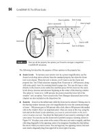
FIGURE 10-5 The Sprayer mode of the Artistic media tool offers a huge number of design
variations.
Sprayer Mode
Object Size
Scaled Size of
Successive Object
Browse
Spray
Order
Add to
Spraylist
Dabs
Open Spraylist
Dialog
Spacing
Reset
Rotation
Properties
Offset
Properties
Delete
Save
Category
Sprayer
File List
Reset
●
Rotation This option is used to set the angle for the first object of the sprayer
style. The Increment option is used to compound rotation values for each subsequent
object. Rotation angles and increment values can be based on the degree measure
relative to the page or the path to which the objects are applied. For example, if you
need a circular pattern whose objects are oriented toward the center of the circle, the
rotation option is the ticket.
●
Offset This option sets the distance between the path you click-drag and the sprayer
objects. Offset can be set to be active (the default) at settings between roughly 0.01
and 13 inches. The direction of the offset can also be set to Alternating (the default),
Left, Random, or Right. To deactivate the Offset options, uncheck the Use Offset
option in the selector, which sets the Offset measure to 0.
●
Reset Clicking this button returns all sprayer style settings in the property bar to
their original default settings.
As with other Artistic media tool modes, you can draw while applying this effect, or
apply an artistic media stroke to an existing line.
With a sprayer style applied and the line selected, you can use property bar options to
edit the effect. Doing this edits the style only as it is applied to your line and not in the
original style in the Sprayer file list. Figure 10-6 shows a sampling of the available sprayer
styles applied using default settings.
CHAPTER 10: Drawing and Editing Objects 275
10
FIGURE 10-6 These are a few of the sprayer styles available in CorelDRAW X5.
To create your own Sprayer brush, first open the Artistic media docker (Window |
Docker | Artistic Media). Create several shapes—they can be groups of objects, and
they can contain any fill you like—and then arrange them horizontally on the page.
Select them, and then click the Save button at the bottom of the docker. Saving and
choosing sprayers to use is almost identical to the way you save and use brushes.
Calligraphy Pens and Applying Media
The Calligraphy tool mode produces results similar to adjusting the nib shape with any
regular Pen tool; however, the width and angle can be conveniently changed dynamically
when you use the Calligraphy tool. Additionally, your artistic approach with this tool is
different than with drawing paths—you click-drag to produce an entire stroke instead of
click-dragging to set a node and a path segment.
You have three options on the property bar when Calligraphic is selected: the Freehand
smoothing (the degree of accuracy when you click-drag); the Stroke width, which sets the
maximum width (because calligraphic stroke are alternately thick and thin); and the
Calligraphic angle (increasing values in this field rotates the stroke evaluated from the
vertical in a counterclockwise direction).
If you use a mouse as an input device instead of a digitizing stylus, using the Calligraphy
tool to draw elegant curves and handsome signatures becomes problematic. A mouse simply
cannot express the degree of accuracy a tablet and stylus do. This doesn’t have to be an
obstacle to creating calligraphic designs, however. Follow this tutorial to learn how to apply
a Calligraphic property—and any artistic media except Pressure—to an existing path.
Defining and Applying Calligraphic Brushstrokes
1. Open the Calligraphy.cdr file. There is a thin centerline on the top, unlocked layer.
The bottom layer is just for reference. Mistral was used as the typeface and is a good
example of calligraphic swoops, curves, and turns. Keep reading this chapter to learn
how to guide a pen tool to create a similar centerline trace over a typeface.
2. With the Pick tool chosen, select the lowercase a after the initial C.
3. Choose the Artistic media tool, and then click the Calligraphic tool on the property
bar. Do not deselect anything.
276 CorelDRAW X5 The Official Guide
Freehand Smoothing
Stroke Width
Calligraphic Angle
4. Here’s the trick: click either the up or down elevator button to the right of the Width
field (or type .2 or .1 in the field instead of using the elevator buttons). What you’ve
done is get the Calligraphic pen to “recognize” that you want to change a value of
the selected path’s calligraphic width. The change isn’t important, it’s the
recognition that applies the calligraphic property to the selected stroke.
5. Continue to adjust the Width (.2" works well at the path’s scale here), and then play
with the Angle—anywhere from 35º to 55º will look good in this example.
6. Because you began with an existing stroke, the calligraphic treatment has an outline
and no fill. Click the black color well on the Color Palette, and then right-click the
No Fill color well to remove the outline.
7. Perform steps 2–6 with the initial C, and then with the brush, dot the i.
Pressure Mode
The last of the artistic media modes was created for users of digital tablets; if you own a
stylus and tablet, you can set up the drivers for the stylus to apply pressure, and CorelDRAW
will read stylus pressure to vary the width of the stroke as you drag across the page. You
have Freehand smoothing and Width controls on the property bar.
If you’re using a mouse, you can:
●
Hold the DOWN ARROW key to make the line smaller as you drag.
●
Only after using the DOWN ARROW key, press the UP ARROW key to widen the
stroke as you click-drag. The maximum width is the value in the num box, and you
cannot exceed this width, so plan ahead.
CHAPTER 10: Drawing and Editing Objects 277
10
Create a value change by clicking the elevator buttons.
Honestly, don’t expect world-class art using the mouse and arrow keys; you might run
into a design situation where you need to vary the width of a stroke, but there are other ways
to edit an existing stroke that produce more refined results.
How to Draw in CorelDRAW
Using artistic media is fun and useful, but it’s now time to learn how to build paths instead
of brushstrokes. In the same group of Curve tools, you’ll find CorelDRAW’s path and node
creation pens. They’re used for both accuracy and artistic expression, and they have varying
degrees of ease of use that correspond directly to their power.
Drawing with Freehand and Polyline Tools
The Freehand and Polyline tools share a common function, giving you the freedom to draw
as if you were sketching by freehand on a physical sketchpad, but the tools work in slightly
different ways. Sketched lines can create a single open or closed vector path. Both tools are
in the toolbox, grouped with other line-creation tools. For mouse users and stylus users
alike, click-dragging initially produces a start node for a path segment and then a path
segment that follows; a node is placed when you release the mouse (or stylus) button, setting
the end of the path segment. To use these tools:
1. Begin by selecting either the Freehand or Polyline tool. Your next step depends on
which tool you choose.
2. If you chose the Freehand tool, you can create a continuous line by click-dragging
a path shape. As soon as the mouse button is released, the line is complete, shown
next. To draw a straight line between two points, click once to define the start point
and a second time somewhere else to define the end point. As soon as you release
the mouse button, the curve is complete.
278 CorelDRAW X5 The Official Guide
Freehand tool
Begin
Click-drag
End (release
mouse button)
3. If you chose the Polyline tool, the technique is slightly different. Use a click-drag
action to create a continuous freehand-style line, but after you release the mouse
button, your cursor can continue extending the curve with path segments. You click-
drag to freehand-style extend the path, or single-click to add a straight line path
segment. A double-click action at your final point defines it as the end point.
4. Both tools produce “bare bones” paths—no fancy strokes, no elegant calligraphic
varying widths. This means you can use the property bar options to make your path
begin with an arrowhead, make the line a dashed line, and change the stroke width.
Using either of these line tools, you have control over the smoothness of path shapes
drawn using click-drag actions by adjusting the Freehand Smoothing option in the property
bar before drawing your path. You can control smoothness after drawing a path by selecting
nodes with the Shape tool and then using the Reduce Nodes spin box. Reduce Nodes has a
range between 0 and 100 percent; lower values apply less smoothing, and higher values
apply more smoothing, as shown in Figure 10-7.
CHAPTER 10: Drawing and Editing Objects 279
10
Polyline tool
Click-drag
Begin
Single click
Click-drag
End (double-click)
Line Styles on Property Bar
Drawing Arcs with the 3-Point Curve Tool
The 3-point curve tool was created for artists to build perfectly smooth arcing line segments,
with complete control over the direction and steepness of the curve between two points.
Making a smooth arc is accomplished in three steps, and you can then extend the curve by
beginning a new 3-point curve at the first curve’s end point, to then close the two curves as
a single object.
You’ll quickly discover that part of the power of the 3-point curve tool is its use in
building a series of connected arcs: you can design French curves and ornamental borders by
280 CorelDRAW X5 The Official Guide
FIGURE 10-7 Freehand Smoothing and Reduce Nodes can change a crude drawn line into
smooth curves.
Original Freehand path (no smoothing)
Path after applying Reduce Nodes
Drag, then release, to define
the end-of-arc point.
First click defines
first arc point.
Move, then click, to
define final shape.
Cursor indicates you’re in
position to extend curve.
Create joining
curve this way.
Release mouse button
over start point of first
curve segment.
Filled object
designing a 3-point curve, positioning your cursor over the end point until you see the cursor
signifying an extension of the last-drawn curve, and then building another 3-point curve.
This is how the head, eyes, and pupils of the cartoon tabby cat in Figure 10-8 were drawn.
Open Ginger tabby.cdr and take the 3-point curve tool out for a spin; Ginger tabby
finished.cdr is the completed illustration you see here. The goatee was drawn using the
artistic media Brush mode.
Using the Bézier and Pen Tools
The Bézier tool and the Pen tool are variations on the same theme of drawing connected
curves and straight segments (unlike the 3-point curve tool) through the action of first
clicking to set a path point, and then either dragging to define a curve behind the click point,
or by clicking (no dragging) to define a straight path segment behind the click point. You’ll
find these tools grouped together with other line-drawing tools.
One of the less obvious differences between the two tools is that the Pen tool offers a
“look ahead” point when you draw with it: before you click or click-drag a point, the
proposed path between the point before you click and the previous (already defined) point
on the path is shown in light blue. When you’re just beginning with CorelDRAW, the choice
between these tools might seem to be:
●
The Pen tool provides intuitive results when you want a path that has both straight
segments and curves.
●
The Bézier tool excels at creating curved segments that are joined smoothly, and
when straight segments are not your design goal.
CHAPTER 10: Drawing and Editing Objects 281
10
FIGURE 10-8 You can create smooth, connecting arcs quickly by using the 3-point curve tool.
The Science of Béziers
Bézier curves (pronounced bezz-ee-aye) were named after French engineer Pierre Bézier,
who published papers on their use after seeing the need for mathematically describing very
smooth curves that are easy to manipulate, to design automobile bodies. A Bézier curve is a
parametric curve, which means it approximates a curve through 2D space, using a convex
control hull that can be described by two points on a curve, and two points off the curve
(called control handles in CorelDRAW) for intuitively reshaping the curve. The Bézier tool
by its nature creates smooth connections between path segments, through the action of click-
dragging to set a path point while at the same time defining the slope of the curve segment
that is created behind the newly created point. When control points are on a curve, they are
called nodes in CorelDRAW. You can also create straight path segments between curves by
using the Bézier tool; it’s a matter of technique. Click-dragging creates smooth curves that
have smooth connections between segments, and the act of clicking without dragging sets a
path point that is not smooth—if you click again in a different location, a straight path
segment is the result.
Because the Bézier tool can produce both curved and straight path segments, there is
almost no distinction between the terms line and curve in the discussions in this chapter. The
shapes of Bézier lines are controlled in part by node properties and by the position of curve
handles. Two paths can have nodes in the same relative page position, but they have
completely different shapes (as shown in Figure 10-9).
282 CorelDRAW X5 The Official Guide
FIGURE 10-9 These two paths each have the same relative node positions, but node properties
make them appear completely different from each other.
Same Node Positions
Nodes can be defined as Cusp, Smooth, or Symmetrical, as shown in Figure 10-10.
Cusp nodes can be used to create a discontinuity in direction between two line segments;
in English, the two segments connect in a non-smooth fashion. Think of the moon being on
the cusp; it’s crescent shaped and this is the sort of shape you can create using cusp node
connections. Smooth nodes cause the path slope and direction to align on either side of a
node; their relationship is in 180-degree opposition, which has the effect of creating a
smooth transition at the node point itself. Control handles surrounding a smooth node may
be unequal distances from the node. Symmetrical nodes are not only smooth, but the control
CHAPTER 10: Drawing and Editing Objects 283
10
Nodes and Control Points
Depending on the type of math used to describe a vector path, nodes (points) connect
a beginning and end point, and the nodes have control handles, at the end of which are
control points, the screen element you use to manipulate curves. The number of control
handles and points depends on the segment connected by each node. For example, an
arc (a curve) connected to a straight line segment has one control handle visible, and it
controls the slope of the curve segment. When two curve segments are connected, you’ll
see two control handles if you click the connecting node with the Shape tool, and this
node can have different connection properties (cusp, smooth—described later in this
chapter). A straight path segment can be described as two nodes connecting the segment,
and the control handles for the nodes coincide in position with the node itself. For all
intents and purposes, the control handles can’t be seen; they become visible when the
segment is changed to a curved segment. The control handles appear on the segment,
and you can move them away from the launch point of the curve and then freely
manipulate the slope of the curve by dragging the control points.
FIGURE 10-10 These paths use different node connection properties.
Cusp node Control handles
Control point
Smooth node
Symmetrical node