Internetworking with TCP/IP- P15 pot
Bạn đang xem bản rút gọn của tài liệu. Xem và tải ngay bản đầy đủ của tài liệu tại đây (470 KB, 10 trang )
Internet Protocol: Connectionless
Datagram
Delivery Chap.
7
0
1 2
3
4
5
6
7
I
COPY
I
OPTION CLASS
I
OPTION NUMBER
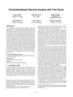
Figure
7.10 The division of the option code octet into
three
fields of length
1,
2,
and
5
bits.
The fields of the
OPTION CODE
consist of a 1-bit
COPY
flag, a 2-bit
OPTION CLASS,
and the 5-bit
OPTION NUMBER.
The
COPY
flag controls how routers treat options
during fragmentation. When the
COPY
bit is set to
I,
it specifies that the option should
be
copied into
all
fragments. When set to
0,
the
COPY
bit means that the option should
only
be
copied into the first fragment and not into all fragments.
The
OPTION CLASS
and
OPTION NUMBER
bits specify the general class of the
option and a specific option in that class. The table in Figure 7.1 1 shows how option
classes are assigned.
Option Class Meaning
0
Datagram or network control
1
Reserved for future use
2
Debugging and measurement
3
Reserved for future use
Figure
7.11 Classes of
IP
options as encoded in the
OPTION
CLASS
bits of
an option code octet.
The table in Figure 7.12 lists examples of options that can accompany an IP da-
tagram and gives their
OPTION CLASS
and
OPTION NUMBER
values. As the list
shows, most options
are
used for control purposes.
Sec.
7.8
Internet
Datagram
Options
109
Option Option
Class Number Length Description
-
-
11
var
var
4
var
4
4
4
var
var
End of option list. Used if options do
not end at end of header (see header
padding field for explanation).
No operation. Used to align octets in a
list of options.
Security and handling restrictions
(for military applications).
Loose source route. Used to request
routing that includes the specified routers.
Record route. Used to trace a route.
Stream identifier. Used to carry a
SATNET stream identifier (obsolete).
Strict source route. Used to specify
a
exact path through the internet.
MTU Probe. Used for path MTU discovery.
MTU Reply. Used for path MTU discovery.
Router Alert. Router should examine this
datagram even if not an addressee.
Internet timestamp. Used to record
timestamps along the route.
Traceroute. Used by traceroute program
to find routers along a path.
Figure
7.12
Examples of
IP
options with their numeric class
and
number
codes.
The
value
var
in the length column stands for
variable.
7.8.1
Record Route Option
The routing and timestamp options are the most interesting because they provide a
way to monitor or control how internet routers route datagram. The
record route
op-
tion allows the source to create an empty list of
IP
addresses and arrange for each router
that handles the datagram to add its
IP
address to the list. Figure
7.13
shows the format
of the record route option.
As described above, the
CODE
field contains the option class and option number
(0
and
7
for record route). The
LENGTH
field specifies the total length of the option as
it appears in the
IP
datagram, including the first three octets. The fields starting with
the one labeled
FIRST IP ADDRESS
comprise the area reserved for recording internet
addresses. The
POINTER
field specifies the offset within the option of the next avail-
able slot.
110
Internet Protocol: Connectionless Datagram Delivery Chap.
7
Figure
7.13
The format of the record route option
in
an
IP
datagram. The
option begins with three octets immediately followed by a list of
addresses. Although the diagram shows addresses in
32
bit un-
its, they are not
aligned
on any octet boundary in a datagram.
0
8
16
24
31
Whenever a machine handles a datagram that has the record route option set, the
machine adds its address to the record route list (enough space must be allocated in the
option by the original source to hold
all
entries that will be needed). To add itself to
the list, a machine first compares the pointer and length fields.
If
the pointer is greater
than the length, the list is full, so the machine forwards the datagram without inserting
its entry.
If
the list is not full, the machine inserts its Coctet
IP
address at the position
specified by the
POINTER,
and increments the
POINTER
by four.
When the datagram arrives, the destination machine can extract and process the list
of
IP
addresses. Usually, a computer that receives a datagram ignores the recorded
route. Using the record route option requires two machines that agree to cooperate; a
computer will not automatically receive recorded routes in incoming datagrams after it
turns on the record route option in outgoing datagrams. The source must agree to en-
able the record route option and the destination must agree to process the resultant list.
CODE(7)
I
LENGTH
7.8.2 Source Route Options
POINTER
Another idea that network builders find interesting is the
source route
option. The
idea behind source routing is that it provides a way for the sender to dictate a path
through the internet. For example, to test the throughput over a particular physical net-
work,
N,
system administrators can use source routing to force
IP
datagrams to traverse
network
N
even if routers would normally choose a path that did not include it. The
ability to make such tests is especially important in a production environment, because
it gives the network manager freedom to route users' datagrams over networks that are
known to operate correctly while simultaneously testing other networks. Of course,
source routing is only useful to people who understand the network topology; the aver-
age user has no need to know or use it.
FIRST IP ADDRESS
SECOND lP ADDRESS
. .
.
Sec.
7.8
Internet Datagram Options
111
IF'
supports two forms of source routing. One form, called
strict source routing,
specifies a routing path by including a sequence of
IP
addresses in the option as Figure
7.14 shows.
0
8
16
24
31
I
CODE(137)
I
LENGTH
I
POINTER
I
IP ADDRESS OF FIRST HOP
IP ADDRESS OF SECOND HOP
Figure
7.14
The strict source route option specifies
an
exact route
by
giving
a
list of
IP
addresses
the
datagram must follow.
Strict source routing means that the addresses specify the exact path the datagram must
follow to reach its destination. The path between two successive addresses
in
the list
must consist of a single physical network; an error results
if
a router cannot follow a
strict source route. The other form, called
loose source routing,
also includes a se-
quence of
IP
addresses. It specifies that the datagram must follow the sequence of IP
addresses, but allows multiple network hops between successive addresses on the list.
Both source route options require routers along the path to overwrite items in the
address list with their local network addresses. Thus, when the datagram anives at its
destination, it contains a list of all addresses visited, exactly like the list produced by
the record route option.
The format of a source route option resembles that of the record route option
shown above. Each router examines the
POINTER
and
LENGTH
fields to see
if
the list
has been exhausted. If it has, the pointer is greater than the length, and the router routes
the datagram to its destination as usual. If the list is not exhausted, the router follows
the pointer, picks up the
IP
address, replaces it with the router's address?, and routes
the datagram using the address obtained from the list.
7.8.3 Timestamp Option
The
timestamp option
works like the record route option in that the timestamp op-
tion contains an initially empty list, and each router along the path from source to desti-
nation fills in one item in the list. Each entry in the list contains two 32-bit items: the
IP
address of the router that supplied the entry and a 32-bit integer timestamp. Figure
7.15 shows the format of the timestamp option.
tA
router
has
one address for
each
interface; it records the address that corresponds to the network over
which
it routes the datagram.
112
Internet Protocol: Connectionless Datagram Delivery Chap.
7
I
FIRST IP ADDRESS
I
0
8
16
24
31
FIRST TIMESTAMP
CODE(68)
1
LENGTH
Figure
7.15
The format of the timestamp option. Bits in
the
FLAGS
field
control the exact format and rules routers use to process this op-
tion.
In the figure, the
LENGTH
and
POINTER
fields are used to specify the length of
the space reserved for the option and the location of the next unused slot (exactly as in
the record route option). The 4-bit
OFLOW
field contains
an
integer count of routers
that could not supply a timestamp because the option was too small.
The value in the 4-bit
FLAGS
field controls the exact format of the option and tells
how routers should supply timestamps. The values are:
POINTER
Flags value Meaning
0
Record timestamps only; omit IP addresses.
1
Precede each timestamp by an IP address
(this is the format shown in Figure
7.15).
3
IP addresses are specified by sender; a
router only records a timestamp if the
next IP address in the list matches the
router's IP address.
OFLOW
1
FLAGS
Figure
7.16
The interpretation of values in the
FLAGS
field of a timestamp
option.
Timestamps give the time and date at which a router handles the datagram, ex-
pressed as milliseconds since midnight, Universal Time?. If the standard representation
for time is unavailable, the router can use any representation of local time provided it
turns on the high-order bit
in
the timestamp field. Of course, timestamps issued by in-
dependent computers are not always consistent even if represented in universal time;
each machine reports time according to its local clock, and clocks may differ. Thus,
timestamp entries should always
be
treated as estimates, independent of the representa-
tion.
It may seem odd that the timestamp option includes a mechanism to have routers
record their IP addresses along with timestamps because the record route option already
provides that capability. However, recording
IP
addresses with timestamps eliminates
t
Universal Time was formerly called Greenwich Mean Time; it
is
the time of day at the prime meridian.
Sec.
7.8
Internet
Datagram
Options
113
ambiguity. Having an address recorded along with each timestamp is also useful
be-
cause it allows the receiver to know exactly which path the datagram followed.
7.8.4
Processing Options During Fragmentation
The idea behind the
COPY
bit in the option
CODE
field should now be clear.
When fragmenting a datagram, a router replicates some
IP
options in all fragments
while it places others in only one fragment. For example, consider the option used to
record the datagram route. We said that each fragment will be handled as an indepen-
dent datagram, so there is no guarantee that all fragments follow the same path to the
destination.
If
all fragments contained the record route option, the destination might re-
ceive a different list of routes from each fragment. It could not produce a single, mean-
ingful list of routes for the reassembled datagram. Therefore, the
IP
standard specifies
that the record route option should only be copied into one of the fragments.
Not all IP options can
be
restricted to one fragment. Consider the source route op-
tion, for example, that specifies how a datagram should travel through the internet.
Source routing information must
be
replicated in
all
fragment headers, or fragments will
not follow the specified route. Thus, the code field for source route specifies that the
option must be copied into all fragments.
7.9
Summary
The fundamental service provided by TCPIIP internet software is a connectionless,
unreliable, best-effort packet delivery system. The Internet Protocol
(IP)
formally speci-
fies the format of internet packets, called
ahtagrams,
and informally embodies the ideas
of connectionless delivery. This chapter concentrated on datagram fonats; later
chapters will discuss
IP
routing and error handling.
Analogous to a physical frame, the
IP
datagram is divided into header and data
areas. Among other infornlation, the datagram header contains the source and destina-
tion IP addresses, fragmentation control, precedence, and a checksum used to catch
transmission errors. Besides fixed-length fields, each datagram header can contain an
options field. The options field is variable length, depending on the number and type of
options used as well as the size of the data area allocated for each option. Intended to
help monitor and control an internet, options allow one to specify or record routing in-
formation, or
to
gather timestamps as the datagram traverses an internet.
FOR FURTHER STUDY
Postel
[I9801
discusses possible ways to approach internet protocols, addressing,
and routing.
In
later publications, Postel [RFC
7911
gives the standard for the Internet
Protocol.
Braden
[RFC
11221
further refines the standard. Hornig
[RFC
8941
specifies
114
Internet Protocol: Connectionless
Datagram
Delivery
Chap.
7
the standard for the transmission of IP datagrarns across an Ethernet. Clark
[RFC
8151
describes efficient reassembly of fragments; Kent and Mogul [I9871 discusses
the
disadvantages of fragmentation.
Nichols et.
al.
[RFC 24741 specifies the differentiated service interpretation of the
service
type
bits in datagram headers, and Blake et.
al.
[RFC 24751 discusses an archi-
tecture for differentiated services.
In
addition to the packet format, many constants
needed in the network protocols are also standardized; the values can
be
found in the
Official Internet Protocols RFC, which is issued periodically.
An
alternative internet protocol suite known as
XNS,
is given in Xerox [1981].
Boggs
et.
al.
[I9801 describes the PARC Universal Packet (PUP) protocol,
an
abstrac-
tion from
XNS
closely related to the
IP
datagram.
EXERCISES
What is the single greatest advantage of having the
IF'
checksum cover only the datagram
header and not the data? What is the disadvantage?
Is it ever necessary to use an
IP
checksum when sending packets over an Ethernet? Why
or why not?
What is the MTU size for a Frame Relay network? Hyperchannel? an
ATM
network?
Do you expect a high-speed local area network to have larger or smaller MTU size than a
wide area network?
Argue that fragments should have small, nonstandard headers.
Find out when the
IP
protocol version last changed. Is having a protocol version number
useful?
Extend the previous exercise by arguing that if the
IP
version changes, it makes more sense
to assign a new frame type than to encode the version number
in
the datagram.
Can you imagine why a one's complement checksum was chosen for
IF'
instead of a cyclic
redundancy check?
What are the advantages of doing reassembly at the ultimate destination instead of doing it
after the datagram travels across one network?
What is the minimum network MTU required to send an
IP
datagram that contains at least
one octet of data?
Suppose you are hired to implement
IP
datagram processing in hardware. Is there any rear-
rangement of fields in the header that would have made your hardware more efficient?
Easier to build?
If
you have access to an implementation of
IP,
revise it and test your locally available
im-
plementations of
IP
to see if they reject
IP
datagrarns with
an
out-of-date version number.
When a minimum-size
IF'
datagram travels across an Ethernet, how large is the frame?
The differentiated services interpretation of the
SERVICE
TYPE
field allows up to
64
separate service levels. Argue that fewer levels are needed (i.e., make a list of all possible
services that a user might access).
The differentiated service definition was chosen to make it backward compatible with the
original type-of-service priority bits. Will the backward compatibility force implementa-
tions to
be
less efficient than an alternative scheme? Explain.
lnternet Protocol: Routing IP
Datagrams
8.1
Introduction
We have seen that all internet services use an underlying, connectionless packet
delivery system, and that the basic unit of transfer in a TCP/IP internet is the
IP
da-
tagram. This chapter adds to the description of connectionless service by describing
how routers forward
IP
datagrams and deliver them to their final destinations. We
think
of the datagram format from Chapter
7
as characterizing the static aspects of the Inter-
net Protocol. The description of routing in this chapter characterizes the operational
as-
pects. The next chapter completes our basic presentation of
IP
by describing how errors
are handled. Chapter
10
then describes extensions for classless and subnet addressing,
and later chapters show how other protocols use
IP
to provide higher-level services.
8.2
Routing In An lnternet
In a packet switching system,
routing
refers to the process of choosing a path over
which to send packets, and
router
refers to a computer making the choice. Routing
oc-
curs at several levels. For example, within a wide area network that has multiple physi-
cal connections between packet switches, the network itself is responsible for routing
packets from the time they enter until they leave. Such internal routing is completely
self-contained inside the wide area network. Machines on the outside cannot participate
in
decisions; they merely view the network as an entity that delivers packets.
116
Internet Protocol: Routing
IP
Datagram Chap.
8
Remember that the goal of
IP
is to provide a virtual network that encompasses
multiple physical networks and offers a connectionless datagram delivery service.
Thus, we will focus on
IP
forwarding,
which is also called
internet routing
or
IP
rout-
ingf.
The information used to make routing decisions is known as
IP
routing informa-
tion.
Like routing within a single physical network,
IP
routing chooses
a
path over
which a datagram should
be
sent. Unlike routing within a single network, the
IP
rout-
ing algorithm must choose how to send a datagram across multiple physical networks.
Routing in
an
internet can
be
difficult, especially among computers that have mul-
tiple physical network connections. Ideally, the routing software would examine net-
work load, datagram length, or the type of service specified in the datagram header
when selecting the best path. Most internet routing software is much less sophisticated,
however, and selects routes based on fixed assumptions about shortest paths.
To understand
IP
routing completely, we must review the architecture of a TCP/IP
internet. First, recall that an internet is composed of multiple physical networks inter-
connected by computers called
routers.
Each router has direct connections to two or
more networks. By contrast, a host computer usually connects directly to one physical
network. We know that it is possible, however, to have a multi-homed host connected
directly to multiple networks.
Both hosts and routers participate in routing an
IP
datagram to its destination.
When an application program on a host attempts to communicate, the TCPJIP protocols
eventually generate one or more
IP
datagram. The host must make an initial routing
decision when it chooses where to send the datagrams. As Figure
8.1
shows, hosts
must make routing decisions even
if
they have only one network connection.
A
path to some
pinations
path to other
4
destinations
L
Figure
8.1
An
example of a singly-homed host that must route datagram.
The host must choose to send a datagram either to router
R,
or to
router
%,
because each router provides the best path to some des-
tinations.
The primary purpose of routers is to make IP routing decisions. What about
multi-homed hosts? Any computer with multiple network connections can act as a
router, and as we will see, multi-homed hosts running TCPJIP have all the software
TChapter
18
describes a related topic known
as
layer
3
switching
or
IP
switching.
Sec.
8.2
Routing
In
An
Internet
117
needed for routing. Furthermore, sites that cannot afford separate routers sometimes use
general-purpose timesharing machines as both hosts and routers. However, the TCPDP
standards draw a sharp distinction between the functions of a host and those of a router,
and sites that
try
to mix host and router functions on a single machine sometimes find
that their multi-homed hosts engage in unexpected interactions. For now, we will dis-
tinguish hosts from routers, and assume that hosts do not perform the router's function
of transferring packets from one network to another.
8.3
Direct And Indirect Delivery
Loosely speaking, we can divide routing into two forms:
direct delivery
and
in-
direct delivery.
Direct delivery, the transmission of a datagram from one machine
across a single physical network directly to another, is the basis on which all internet
communication rests. Two machines can engage in direct delivery only if they both at-
tach directly to the same underlying physical transmission system (e.g., a single Ether-
net).
Indirect delivery
occurs when the destination is not on a directly attached net-
work, forcing the sender to pass the datagram to a router for delivery.
8.3.1
Datagram Delivery Over
A
Single Network
We know that one machine on a given physical network can send a physical frame
directly to another machine on the same network. To transfer an
IP
datagram, the
sender encapsulates the datagram in a physical frame, maps the destination
IP
address
into a physical address, and uses the network hardware to deliver it. Chapter
5
present-
ed
two possible mechanisms for address resolution, including using the
ARP
protocol
for dynamic address binding on Ethernet-like networks. Chapter
7
discussed datagram
encapsulation. Thus, we have reviewed all the pieces needed to understand direct
delivery. To summarize:
Transmission of an
IP
datagram between two machines on a single
physical network does not involve routers. The sender encapsulates
the datagram in a physical frame, binds the destination
ZP
address to
a physical hardware address, and sends the resulting frame directly to
the destination.
How does the sender know whether the destination lies on a directly connected net-
work? The test is straightforward. We know that
IP
addresses are divided into a
network-specific prefix and a host-specific suffix. To see
if
a destination lies on one of
the directly connected networks, the sender extracts the network portion of the destina-
tion
IP
address and compares it to the network portion of its own
IP
address(es).
A
match means the datagram can
be
sent directly. Here we see one of the advantages of
the Internet address scheme, namely: