Database Modeling & Design Fourth Edition- P4 ppsx
Bạn đang xem bản rút gọn của tài liệu. Xem và tải ngay bản đầy đủ của tài liệu tại đây (165.87 KB, 5 trang )
2CHAPTER 1Introduction
In this chapter, we review the basic concepts of database manage-
ment and introduce the role of data modeling and database design in
the database life cycle.
1.1 Data and Database Management
The basic component of a file in a file system is a data item, which is the
smallest named unit of data that has meaning in the real world—for
example, last name, first name, street address, ID number, or political
party. A group of related data items treated as a single unit by an applica-
tion is called a record. Examples of types of records are order, salesperson,
customer, product, and department. A file is a collection of records of a
single type. Database systems have built upon and expanded these defi-
nitions: In a relational database, a data item is called a column or
attribute; a record is called a row or tuple; and a file is called a table.
A database is a more complex object; it is a collection of interrelated
stored data that serves the needs of multiple users within one or more
organizations, that is, interrelated collections of many different types of
tables. The motivations for using databases rather than files include
greater availability to a diverse set of users, integration of data for easier
access to and updating of complex transactions, and less redundancy of
data.
A database management system (DBMS) is a generalized software sys-
tem for manipulating databases. A DBMS supports a logical view
(schema, subschema); physical view (access methods, data clustering);
data definition language; data manipulation language; and important
utilities, such as transaction management and concurrency control, data
integrity, crash recovery, and security. Relational database systems, the
dominant type of systems for well-formatted business databases, also
provide a greater degree of data independence than the earlier hierarchi-
cal and network (CODASYL) database management systems. Data inde-
pendence is the ability to make changes in either the logical or physical
structure of the database without requiring reprogramming of applica-
tion programs. It also makes database conversion and reorganization
much easier. Relational DBMSs provide a much higher degree of data
independence than previous systems; they are the focus of our discus-
sion on data modeling.
Teorey.book Page 2 Saturday, July 16, 2005 12:57 PM
1.2 The Database Life Cycle 3
1.2 The Database Life Cycle
The database life cycle incorporates the basic steps involved in designing
a global schema of the logical database, allocating data across a com-
puter network, and defining local DBMS-specific schemas. Once the
design is completed, the life cycle continues with database implementa-
tion and maintenance. This chapter contains an overview of the data-
base life cycle, as shown in Figure 1.1. In succeeding chapters, we will
focus on the database design process from the modeling of requirements
through logical design (steps I and II below). The result of each step of
the life cycle is illustrated with a series of diagrams in Figure 1.2. Each
diagram shows a possible form of the output of each step, so the reader
can see the progression of the design process from an idea to actual data-
base implementation. These forms are discussed in much more detail in
Chapters 2 through 6.
I. Requirements analysis. The database requirements are deter-
mined by interviewing both the producers and users of data and
using the information to produce a formal requirements specifi-
cation. That specification includes the data required for process-
ing, the natural data relationships, and the software platform for
the database implementation. As an example, Figure 1.2 (step I)
shows the concepts of products, customers, salespersons, and
orders being formulated in the mind of the end user during the
interview process.
II. Logical design. The global schema, a conceptual data model dia-
gram that shows all the data and their relationships, is devel-
oped using techniques such as ER or UML. The data model
constructs must ultimately be transformed into normalized (glo-
bal) relations, or tables. The global schema development meth-
odology is the same for either a distributed or centralized
database.
a.Conceptual data modeling. The data requirements are analyzed
and modeled using an ER or UML diagram that includes, for
example, semantics for optional relationships, ternary rela-
tionships, supertypes, and subtypes (categories). Processing
requirements are typically specified using natural language
Teorey.book Page 3 Saturday, July 16, 2005 12:57 PM
4CHAPTER 1Introduction
expressions or SQL commands, along with the frequency of
occurrence. Figure 1.2 [step II(a)] shows a possible ER model
representation of the product/customer database in the mind
of the end user.
Figure 1.1 The database life cycle
Determine requirements
Model
Information requirements
Integrate views
Transform to SQL tables
[multiple views]
[else]
[else]
[defunct]
[special requirements]
[single view]
Normalize
Select indexes
Denormalize
Implement
Monitor and detect changing requirements
Physical design
Logical design
Implementation
Teorey.book Page 4 Saturday, July 16, 2005 12:57 PM
1.2 The Database Life Cycle 5
b.View integration. Usually, when the design is large and more
than one person is involved in requirements analysis, multi-
ple views of data and relationships result. To eliminate redun-
dancy and inconsistency from the model, these views must
eventually be “rationalized” (resolving inconsistencies due to
variance in taxonomy, context, or perception) and then con-
solidated into a single global view. View integration requires
the use of ER semantic tools such as identification of syn-
onyms, aggregation, and generalization. In Figure 1.2 [step
Figure 1.2 Life cycle results, step-by-step
Step I Requirements Analysis (reality)
Step II Logical design
Products
Customers
Salespersons
Order
s
Step II(a) Conceptual data modeling
Step II(b) View integration
Integration
of retail
salesperson’s
and customer’s
views
Retail
salesperson
view
N
NN
N
N
1
customer
served-by
orders
salesperson
product
sold-by
Customer
view
N
N
N
N
N
1
11
customer
places
served-by
salesperson
fills-out
product
for
order
N1
customer
places
order
Teorey.book Page 5 Saturday, July 16, 2005 12:57 PM
6CHAPTER 1Introduction
II(b)], two possible views of the product/customer database
are merged into a single global view based on common data
for customer and order. View integration is also important for
application integration.
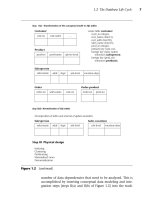
c.Transformation of the conceptual data model to SQL tables. Based
on a categorization of data modeling constructs and a set of
mapping rules, each relationship and its associated entities
are transformed into a set of DBMS-specific candidate rela-
tional tables. We will show these transformations in stan-
dard SQL in Chapter 5. Redundant tables are eliminated as
part of this process. In our example, the tables in step II(c) of
Figure 1.2 are the result of transformation of the integrated
ER model in step II(b).
d.Normalization of tables. Functional dependencies (FDs) are
derived from the conceptual data model diagram and the
semantics of data relationships in the requirements analysis.
They represent the dependencies among data elements that
are unique identifiers (keys) of entities. Additional FDs that
represent the dependencies among key and nonkey attributes
within entities can be derived from the requirements specifi-
cation. Candidate relational tables associated with all derived
FDs are normalized (i.e., modified by decomposing or split-
ting tables into smaller tables) using standard techniques.
Finally, redundancies in the data in normalized candidate
tables are analyzed further for possible elimination, with the
constraint that data integrity must be preserved. An example
of normalization of the Salesperson table into the new
Salesperson and SalesVacations tables is shown in Figure
1.2 from step II(c) to step II(d).
We note here that database tool vendors tend to use the
term logical model to refer to the conceptual data model, and
they use the term physical model to refer to the DBMS-specific
implementation model (e.g., SQL tables). Note also that many
conceptual data models are obtained not from scratch, but
from the process of reverse engineering from an existing DBMS-
specific schema [Silberschatz, Korth, and Sudarshan, 2002].
III. Physical design. The physical design step involves the selec-
tion of indexes (access methods), partitioning, and clustering of
data. The logical design methodology in step II simplifies the
approach to designing large relational databases by reducing the
Teorey.book Page 6 Saturday, July 16, 2005 12:57 PM