Database Modeling & Design Fourth Edition- P7 ppsx
Bạn đang xem bản rút gọn của tài liệu. Xem và tải ngay bản đầy đủ của tài liệu tại đây (155.95 KB, 5 trang )
2.1 Fundamental ER Constructs 17
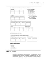
Figure 2.2 Degrees, connectivity, and attributes of a relationship
Representation & Example
D
egree
recursive
binary
binary
ternary
one-to-one
one-to-many
many-to-many
optional
mandatory
E
xistence
Connectivity
Department
Department
Department
Office
Employee
Employee
Employee
Employee
Employee
Project
is-
managed-
by
has
is-
managed-
by
is-
occupied-
by
works-on
1
1
1
1
1
N
N
N
N
1
Concept
Employee
Department
Division
Project
Skill
Employee
N
N
N
N
manages
manager
subordinate
is-
subunit-
of
uses
1
1
N
task-assignment
start-date
Teorey.book Page 17 Saturday, July 16, 2005 12:57 PM
18 CHAPTER 2 The Entity-Relationship Model
2.1.3 Connectivity of a Relationship
The connectivity of a relationship describes a constraint on the connec-
tion of the associated entity occurrences in the relationship. Values for
connectivity are either “one” or “many.” For a relationship between the
entities Department and Employee, a connectivity of one for Depart-
ment and many for Employee means that there is at most one entity
occurrence of Department associated with many occurrences of
Employee. The actual count of elements associated with the connectiv-
ity is called the cardinality of the relationship connectivity; it is used
much less frequently than the connectivity constraint because the actual
values are usually variable across instances of relationships. Note that
there are no standard terms for the connectivity concept, so the reader is
admonished to consider the definition of these terms carefully when
using a particular database design methodology.
Figure 2.2 shows the basic constructs for connectivity for binary rela-
tionships: one-to-one, one-to-many, and many-to-many. On the “one”
side, the number one is shown on the connection between the relation-
ship and one of the entities, and on the “many” side, the letter N is used
on the connection between the relationship and the entity to designate
the concept of many.
In the one-to-one case, the entity Department is managed by exactly
one Employee, and each Employee manages exactly one Department.
Therefore, the minimum and maximum connectivities on the “is-man-
aged-by” relationship are exactly one for both Department and
Employee.
In the one-to-many case, the entity Department is associated with
(“has”) many Employees. The maximum connectivity is given on the
Employee (many) side as the unknown value N, but the minimum con-
nectivity is known as one. On the Department side the minimum and
maximum connectivities are both one, that is, each Employee works
within exactly one Department.
In the many-to-many case, a particular Employee may work on
many Projects and each Project may have many Employees. We see that
the maximum connectivity for Employee and Project is N in both direc-
tions, and the minimum connectivities are each defined (implied) as
one.
Some situations, though rare, are such that the actual maximum
connectivity is known. For example, a professional basketball team may
be limited by conference rules to 12 players. In such a case, the number
Teorey.book Page 18 Saturday, July 16, 2005 12:57 PM
2.1 Fundamental ER Constructs 19
12 could be placed next to an entity called “team members” on the
many side of a relationship with an entity “team.” Most situations, how-
ever, have variable connectivity on the many side, as shown in all the
examples of Figure 2.2.
2.1.4 Attributes of a Relationship
Attributes can be assigned to certain types of relationships as well as to
entities. An attribute of a many-to-many relationship, such as the
“works-on” relationship between the entities Employee and Project (Fig-
ure 2.2), could be “task-assignment” or “start-date.” In this case, a given
task assignment or start date only has meaning when it is common to an
instance of the assignment of a particular Employee to a particular
Project via the relationship “works-on.”
Attributes of relationships are typically assigned only to binary
many-to-many relationships and to ternary relationships. They are not
normally assigned to one-to-one or one-to-many relationships, because
of potential ambiguities. For example, in the one-to-one binary relation-
ship “is-managed-by” between Department and Employee, an attribute
“start-date” could be applied to Department to designate the start date
for that department. Alternatively, it could be applied to Employee as an
attribute for each Employee instance, to designate the employee’s start
date as the manager of that department. If, instead, the relationship is
many-to-many, so that an employee can manage many departments
over time, then the attribute “start-date” must shift to the relationship,
so each instance of the relationship that matches one employee with
one department can have a unique start date for that employee as man-
ager of that department.
2.1.5 Existence of an Entity in a Relationship
Existence of an entity occurrence in a relationship is defined as either
mandatory or optional. If an occurrence of either the “one” or “many”
side entity must always exist for the entity to be included in the relation-
ship, then it is mandatory. When an occurrence of that entity need not
always exist, it is considered optional. For example, in Figure 2.2 the
entity Employee may or may not be the manager of any Department,
thus making the entity Department in the “is-managed-by” relationship
between Employee and Department optional.
Teorey.book Page 19 Saturday, July 16, 2005 12:57 PM
20 CHAPTER 2 The Entity-Relationship Model
Optional existence, defined by a zero on the connection line between
an entity and a relationship, defines a minimum connectivity of zero.
Mandatory existence defines a minimum connectivity of one. When exist-
ence is unknown, we assume the minimum connectivity is one (that is,
mandatory).
Maximum connectivities are defined explicitly on the ER diagram
as a constant (if a number is shown on the ER diagram next to an
entity) or a variable (by default if no number is shown on the ER dia-
gram next to an entity). For example, in Figure 2.2, the relationship
“is-occupied-by” between the entity Office and Employee implies that
an Office may house from zero to some variable maximum (N) number
of Employees, but an Employee must be housed in exactly one Office,
that is, mandatory.
Existence is often implicit in the real world. For example, an entity
Employee associated with a dependent (weak) entity, Dependent, can-
not be optional, but the weak entity is usually optional. Using the con-
cept of optional existence, an entity instance may be able to exist in
other relationships even though it is not participating in this particular
relationship.
The term existence is also associated with identification of a data
object. Many DBMSs provide unique identifiers for rows (Oracle ROW-
IDs, for example). Identifying an object such as a row can be done in an
existence-based way. It can also be done in a value-based way by identi-
fying the object (row) with the values of one or more attributes or col-
umns of the table.
2.1.6 Alternative Conceptual Data Modeling Notations
At this point we need to digress briefly to look at other conceptual data
modeling notations that are commonly used today and compare them
with the Chen approach. A popular alternative form for one-to-many
and many-to-many relationships uses “crow’s-foot” notation for the
“many” side (see Figure 2.3a). This form is used by some CASE tools,
such as Knowledgeware’s Information Engineering Workbench (IEW).
Relationships have no explicit construct but are implied by the connec-
tion line between entities and a relationship name on the connection
line. Minimum connectivity is specified by either a 0 (for zero) or perpen-
dicular line (for one) on the connection lines between entities. The term
intersection entity is used to designate a weak entity, especially an entity
that is equivalent to a many-to-many relationship. Another popular form
Teorey.book Page 20 Saturday, July 16, 2005 12:57 PM
2.1 Fundamental ER Constructs 21
used today is the IDEFIX notation [IDEF1X, 2005], conceived by Robert
G. Brown [Bruce, 1992]. The similarities with the Chen notation are
obvious in Figure 2.3b. Fortunately, any of these forms is reasonably easy
to learn and read, and their equivalence with the basic ER concepts is
obvious from the diagrams. Without a clear standard for the ER model,
however, many other constructs are being used today in addition to the
three types shown here.
(a)
Figure 2.3 Conceptual data modeling notations
ER model constructs
using the
Chen notation
ER model constructs using the
"crow's-foot” approach
[Knowledgeware]
Department
Division has Department
Department
Division
Office Employee
Employee
Recursive binary relationship
Recursive entity
Project
Department
Employee
is-
managed-
by
is-
occupied-
by
is-
occupied-
by
works-
on
works-
on
11
1
Office
Employee
Employee
1
Employee-
job-history
weak entity
Project
N
N
N
N
Employee
Employee-
job-history
intersection entity
is-group-leader-of
has
max = 1
min = 0
min = 1
max = 1
is-
managed-
by
Employee
Employee
1N
is-
group-leader-
of
Teorey.book Page 21 Saturday, July 16, 2005 12:57 PM