Chapter 8: Advanced Design Techniques and Recent Design Examples of CMOS OP AMPs doc
Bạn đang xem bản rút gọn của tài liệu. Xem và tải ngay bản đầy đủ của tài liệu tại đây (786.54 KB, 42 trang )
Chapter 8 Advanced Design Techniques and Recent
Design Examples of CMOS OP AMPs
§8-1 Advanced Design Techniques of CMOS OP AMPs
§8-1.1 Improved PSRR and frequency compensation
ss
o
mI
gd
ss
GS
mss
o
I
gs
ss
out
V
I
gC
C
V
V
gV
I
C
C
V
V
∂
∂
+
∂
+
∂
∂
≈
∂
∂
3
1
1
2
1
2
1
DD
o
mI
gs
mDD
o
I
gd
DD
out
V
I
gC
C
gV
I
C
C
V
V
∂
∂
+
∂
∂
−≈
∂
∂
13
2
1
2
1
1
Where
o
I represents the input stage bias current.
If
o
I is independent of
ss
V and
DD
V
and the input devices have no body effect.
==> 0→
∂
∂
ss
out
V
V
I
gd
DD
out
C
C
V
V
−→
∂
∂
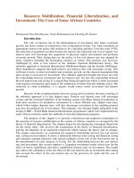
Ref.: IEEE JSSC, vol. SC-15, pp.929-938, Dec. 1980
*
REF
I is generated by using the power supply independent current source.
*
BIAS
V is nearly independent of
DD
V and
ss
V .
*It is better to use separate p-wells for
1
M and
2
M to avoid the body effect.
P.6-26
+V
DD
M
3
M
4
M
6
OP AMP
V
o
M
7
M
8
V
+
V
-
M
1
M
2
M
5
Io
V
BIAS
M
9
M
10
M
11
M
12
I
REF
BIAS GENERATOR
-V
SS
8 - 1
CHUNG-YU WU
*Tracking RC compensation
Conceptual circuits :
In the quiescent case ,Vin2=VOS2
The requires Rc is ]/)[(/1]/)(1[/1
22 CLmLdm
CCCcgCcCCgRc +≈++=
Thus LHP zero=LHP pole P2
and P3 becomes the second pole.
The stability considerations,
13
PAP
do
≥
or
L
m
m
cc
g
g
Cc
1
2
1
≥
allows a smaller gm2 and larger
L
C
* RcR
dsA
≈ indep of temperature, process , and supply variations.
=>Tracking design to make sure that z=P
2
=>No pole-zero doublet problem!
Vos2
+VDD
g
m1
V
IN
V
IN2
Mc
(M10)
I
M
B
(M6)
C
L
KI
M
A
(M8)
C
C
(R
C
)
+
-
-
+
Voltage
source
-VSS
Rc
Ccg
CCc
R
CCc
Cc
KLWLWLW
m
L
dsA
L
CBA
≈
+
≈=>
+
••≈
2
2/1
])/()/[()/( If
8 - 2
CHUNG-YU WU
CMOS Design
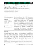
* M17,Cc : Tracking RC compensation.
* M9,M11:Sharing the separate n-well.
* V
BIAS
is not strictly independent of V
DD
and V
SS.
§8-1.2 Improved frequency compensation technique.
Ref.: IEEE JSSC ,vol.sc-18, pp 629-633, Dec.1983
Grounded gate cascode compensation
+VDD
-VSS
M1
M3
M2
M4
M5
M6
M7
M8
M9
M11
M10
M12
M14
M16
M15
M13
M17
Cc
+
-
VBIAS
Vout
+VDD
M12 M11
M13
I
BIAS
M14 M15
M16
V
BIAS1
V
BIAS2
V
BIAS1
M3
M4
M2 M1
+ -
M5 M9
M7
M6
M10
Vo
Cc
5pF
M8
3x
2x
3x
M
C1
M
C2
3x
8 - 3
CHUNG-YU WU
MB
MB,Cgs7:low pass filter for high frequency noises.
M8,M9,M10:new compensation circuit.
M11~M16:Bias generator.
Conceptual circuits:
Net current in C
C
)(
oc
V
dt
d
C enters the second stage.
The input voltage Vi can’t reach the node A
è * Better PSRR (∵ no low-freq. zero ) , especially PSRR
* Allow larger capacitive loads.
* Slight increase in complexity , random offset and noise.
§ 8-1.3 Improved cascode structure
1. To improve gain:
Ref: IEEE JSSC , vol. SC-17, pp. 969-982, Dec. 1982 ☆☆
8 - 4
CHUNG-YU WU
_
+
gm1
2Io
+V
DD
I
1
Cc
-gm2
CS1
I
1
CS2
R
1
R
2
Vo
-V
SS
A
Vi
Vo
+V
DD
Cc
Rc
M6
M7
M8
M2
M9
M1
M1A
M2A
M3A
M4A
-V
SS
M4
M3
* Substantial reduction in input-stage common-mode range.
* Improved wilson current source is used as the load to improve the balance of the
first stage.
2. Single-stage push-pull class AB CMOS OP AMP
Ref: IEEE JSSC , vol.sc-17, pp.969-982, Dec. 1982
* Inverting mode only. (+ grounded)
* Capable of high current driving and
high voltage gain.
* Not a differential-amplifier-based
OP AMP.
3. Cascoded CMOS OP AMP with high ac PSRR
Ref: (1) IEEE JSSC , vol. SC-19, pp.55-61, Feb. 1984
(2) IEEE JSSC , vol SC-19, pp. 919-925, Dec. 1984
1) Original version
Chrarcteristics:
V
DD
=V
SS
=2.5V
Input offset voltage 5mV
Supply current 100ìA
Output voltage range -V
SS
~V
DD
Input common mode range -V
SS
+1.47V ~ V
DD
CMRR @ 1KHz 99dB
Unity-gain frequency 1.0MHz
Slew rate 1.8 V/ìsec
_
+
M5
M6
M7
M2 M4
M1 M3
M8
M9
M10
OUT
IN
BIAS
Cc
+VDD
-VSS
+VDD
Mp2
200/10
200/10
Mp3
Mp4
25/10
1125/10
Mp5
C
L
Vout
Cc
Mp7
100/10
M
N8
500/10
M
N7
42.5/10
M
N6
42.5/10
M
N5
100/10
Mp5
100/10
M
N1
M
N2
50/10
50/10
M
N4
200/10
M
N3
M
N9
100/10
100/10
I
BIAS
5µA
-VSS
+ -
A
8 - 5
CHUNG-YU WU
* Better input common-mode range.
* Vic↓è V
DSN4
↓è I
DSN4
↓è V
A
↑è M
N8
is turned on è V
out
→-V
SS
voltage spike at V
out
.
* The possible spike in the settling period.
2) Improved version
*
1312
,MM and
14
M : Let the drain bias currents of
10
M and
11
M follow
the change of
7D
I under positive input common mode voltage.
⇒
No voltage spike at
out
V
Also serves as CMFB
* Better PSRR and input common-mode range.
*
c
C is decoupled from the gate of the driver
8
M .
4.Simple cascoded CMOS OP AMP
Ref.:IEEE JSSC , vol.SC-19 , pp.919~925 , Dec. 1984
+VDD
V
BIAS1
M7
M1
M2
M12
M5
M6
M8
M9
M11
M10
M14
V
BIAS2
V
BIAS3
Cc
Vout
-VSS
M13
-
+
M3
M4
+VDD
M5
M6
-VSS
M8
M3
M4
M1 M2
M5
M9
Cc
Vout
V
BIAS1
V
BIAS2
-
+
* Good PSRR
* Reduced input common
range.
⇒
restrict its applications
to those which use a virtual
ground.
8 - 6
CHUNG-YU WU
5.Single-stage cascode OTA
Ref.: IEEE JSSC , vol. SC-20 , pp.657~665 , June 1985 ☆☆
109
,TT : Cascode structure
* Output conductance ↓ without any noise penalty and with only a very small
reduction of phase margin.
⇒
Gain↑ no any compensation is necessary.
* Maximum output swing↓
§ 8-2 Advanced Design Techniques on High-frequency Non-differential-type CMOS
OP AMPs
1. Single-ended push-pull CMOS OP AMP
*Current-gain-based design
T6
T1
T3
T4
T2
T5
T11
I
BIAS
T13
T7
T9
T10
T8
In-
In+
1
A
T12
T14
T17
T15
Io
Out
C
L
-
+
8 - 7
CHUNG-YU WU
TABLE I
Parameter Measured Value
DC-Open Circuit Gain
Unity0Gain Bandwidth
Phase Margin
Slew Rate
PSRR (DC
+
)
PSRR (DC
-
)
Input Offset Voltage
CMRR (DC)
Output Voltage Swing
Output Resistance
Input Referred Noise (@1KHz)
DC-Power Dissipation
69dB
70MHz
40
o
200 sec/
µ
V
68dB
66dB
10mV
62dB
1.5V
P
3
Ω
M
0.54 HzV /
µ
1.1mWatt
VV
DD
3+= ; VV
CC
3−= ; AI
B
µ
50
1
= ; CL=1pF
TABLE II
Bias Current Unity-Gain
Bandwidth
DC-Open Circuit
Voltage Gain
DC-Power
Dissipation
25 A
µ
50 A
µ
100 A
µ
50MHz
70MHz
100MHz
70dB
69dB
66dB
0.55mW
1.1mW
2.2mW
M5
M8
M9
M14
M13
M15
M1 M2
M3
M4
M10
M11
M12 M16
M7
M6
+VDD
-Vcc
OUTPUT
CL
IB1
INPUT
8 - 8
CHUNG-YU WU
VV
DD
3+= ; VV
CC
3−= ; CL=1pF
2.Low output resistance CMOS OP AMP
*
L
C is a compensation capacitor
*For low-resistance load
*Smaller maximum output voltage swing.
* pFCAI
LB
1,50
1
==
µ
, MHzf
u
60=
§ 8-3 Advanced Design Techniques on High-drive MOS Power or Buffer OP AMPs
§ 8-3.1 Efficient Output Stages.
A. CMOS output stage using a biplar emitter follower and a low-threshold PMOS
source follower.
+ V
DD
- V
SS
V
BIAS
V
in
V
out
M5
M8
M9
M14
M13
M15
M1 M2
M3
M4
M10
M11
M12
M16
M7
M6
+VDD
-Vcc
OUTPUT
CL
IB1
INPUT
M17
M22
M21
M20
M19
M18
8 - 9
CHUNG-YU WU
B. Complementary class B output stage using compound devices with
common-source output MOS.
V
out
+ V
DD
- V
SS
V
i
M
P
M
N
A
A
§ 8-3.2 High-drive power or buffer CMOS OP AMPs
1. Large swing CMOS power amplifier (National Semiconductor)
+
-
+
-
+
-
+ V
DD
-V
SS
V
IN
V
OUT
M
9
M
10
M
11
M
12
M
6
M
6A
M
13
M
8
M
8A
M
17
M
16
C
0
V
BIASN
V
BIASN
A
1
A
2
8 - 10
CHUNG-YU WU
* Noninverting unity gain amplifier
+
-
~
V
out
+ V
DD
V
i
M
6
A
1
outin
VV ≅
6
M provides the negative feedback
*
1
A ,
6
M and
2
A ,
A
M
6
form a class AB push-pull output stage.
* Full swing from
DD
V
+
to
SS
V−
* ,,,
11109
MMM and
12
M form a current feedback to stablize the bias current
of
6
M and
A
M
6
.
Offset in
1
A ,e.g. ↑↓⇒↑⇒
−
611 DMoutAinA
IVV and ↑↑⇒
119 DMDM
II
and ↑↑⇒
AGSMDM
VI
812
and ↓
+
2inA
V ,↑⇒
out
V i.e.
↓↓⇒↑⇒
−+
11 inAoutinA
VVV (virtual short between + and -) ↓⇒
−
2inA
V
througt
8
M
⇒
All the bias voltage and current are restored to the normal
values and the offset is absorbed by
A
M
8
.
Since the current feedback is not unity gain ,some current variation in
transistors
6
M and
A
M
6
still exists.
V
CC
V
SS
V
SS
V
OUT
V
IN
V
BIASN
M
3
M
4
M
6
MPC
C
C
M
2
M
1
M
5
8 - 11
CHUNG-YU WU
Large positive common mode range allows
6
M to source large amount of
current to the load. (because
outin
VV ≅ )
The maximum
6GS
V which
1
M and
2
M still in the saturation region is
)VVV())VVV(V(V
1THINCC1DSAT1GSINDDmax6GS
+
−
−
=
+
−
−
−
=
↑↑⇒↑⇒⇒
6DMmax6GS1TH
IVV
(1). Threshold implant to increase
1THO
V
(2). Negative substrate bias
SS
V− to increase
1TH
V
+
-
+ V
CC
- V
SS
V
OUT
V
BIASP
V
BIASN
V
IN
M
16
C
0
M
8
M
17
M
3H
M
4H
M
3
M
4
M
1
M
2
M
5
M
P4
M
P3
M
N3
M
N4
M
P5
C
C
M
6
M
8A
M
RC
M
5A
M
13
M
12
M
11
M
RF
C
F
M
10
M
9
M
N5A
M
N4A
M
P4A
M
P3A
M
N3A
M
4HA
M
3HA
M
4A
M
3A
M
2A
M
1A
M
5A
* The input stage is not shown in the diagram.
*
17816
,, MMM form the second stage with
D
C the Miller compensation
capacitor.
* If 0,
5
→−→
DSMSSout
VVV and .0
5
→
DSM
I
321
,, MMM⇒ and
4
M are off
H
M
3
⇒ and
H
M
4
are still on to keep .0
6
VV
GS
≅
Otherwise ,
6
M will be turned on.
Similarly,
HA
M
3
and
HA
M
4
turn off
A
M
6
in the positive voltage swing
*
4433
,,,
PNNP
MMMM and
5P
M are output short-circuit protection circuitry.
Normally,
5P
M is off.
8 - 12
CHUNG-YU WU
When ,60
6
mAI
DM
≅ .
543
↑↑⇒↑⇒
GSMPDMNDMP
VII
6DM
I⇒ is limited to approximately 60 mA.
Table I
POWER AMPLIFIER PREFORMANCE
Parameter Simulation Measured
Results
Power dissipation( V5
±
)
A
vol
F
u
V
offset
PSRR+(dc)
(1KHz)
PSRR-(dc)
(1KHz)
THD V
IN
=3.3V
p
R
L
=300Ω
C
L
=1000 pF
V
IN
=4.0V
p
R
L
=15 kΩ
C
L
=200 pF
T
settling
(0.1%)
Slew rate
1/f noise at 1KHz
Broad-band noise
Die area
7.0mW
82dB
500KHz
0.4mV
85dB
81dB
104dB
98dB
0.03%
0.08%
0.05%
0.16%
3.0us
0.8V/us
N/A
N/A
5.0mW
83dB
420KHz
1mV
86dB
80dB
106dB
98dB
0.13%(1KHz)
0.32%(4KHz)
0.13%(1KHz)
0.20%(4KHz)
<5.0us
0.6V/us
130nV/Hz
49nV/Hz
1500mils
2
TABLE II
COMPONENT SIZES ( µm, pF )
8 - 13
CHUNG-YU WU
8 - 14
CHUNG-YU WU
MI6
MI7
M8
M1,M2
M3,M4
M3H,M4H
M5
M6
MRC
CC
M1A,M2A
M3A,M4A
M3HA,M4HA
M5A
M6A
MRF
CF
184/9
66/12
184/6
36/10
194/6
16/12
145/12
2647/6
48/10
11.0
88/12
196/6
10/12
229/12
2420/6
25/12
10.0
M8A
M13
M9
M10
M11
M12
MP3
MN3
MP4
MN4
MP5
MN3A
MP3A
MN4A
MP4A
MN5A
481/6
66/12
27/6
6/22
14/6
140/6
8/6
244/6
43/12
12/6
6/6
6/6
337/6
24/12
20/12
6/6
Maximum loads :
Ω
300 and 1000pF to ground.
Ref.:IEEE JSSC , vol.SC-18 , pp.624-629 , Dec.1983
2. High-performance CMOS power amplifier (Siemens AG)
(1). New input stage : 3 gain stages.
+ V
DD
- V
SS
BIAS
+ -M
1
M
2
M
3
M
4
M
5
M
6
M
7
M
8
M
9
M
10
M
11
M
13
M
12
C
C
* Cc is connected to the source of M
9
to improve PSRR
* Three poles and one zero :
1281136
1386
2
mmmmc
mmm
ggCggC
ggg
Z
+
−
= LHP.
cm
ods
Cg
gg
P
13
10
1
−
≅
2/1
2
8
1
1388
32
2
)(
2
)(
,
+
−±
+−
≅
cO
COm
O
mm
cO
Ocm
CC
CCg
CC
gg
j
CC
CCg
PP
where
1312 dsdso
ggg +≡
1312 dbdbLO
CCCC ++=
9911131 gddbdbgs
CCCCC +++=
Design guidelines for stability :
8m
g large ,
613 mm
gg >>
(2). Output stage
+ V
DD
- V
SS
V
BIAS
V
in
V
out
Class AB source follower
* One pole and one zero at high frequencies.
* Not full swing
8 - 15
CHUNG-YU WU
+
-
+
-
+ V
DD
- V
SS
V
out
V
in
M
1
M
2
A
1
A
2
Pseudo source follower
* The quiescent current in M
1
and M
2
will vary widely with variations in
Vos1 and Vos2.
* Suitable common-mode range of the two amplifiers A
1
and A
2
are
required.
* Large phase shift at high frequencies due to A
1
and A
2
⇒ stability
problem.
Combined output stage:
* M
1
and M
2
are turned off in the quiescent state by building a small offset
voltage into A
1
and A
2
⇒ M
3
-M
6
control the output quiescent currents.
* M
2
(M
1
) sinks (sources) approximately 95% of the required currents.
* M
1
and M
2
provide a high-frequency feed-forward path.
+
-
+
-
+ V
DD
- V
SS
BIAS
V
IN
M
3
M
4
V
os
V
os
AMP 1
AMP 2
M
5
M
6
M
15
M
17
error amp.
error amp.
Still has a smaller swing limited by M
5
, M
6
.
8 - 16
CHUNG-YU WU
8 - 17
CHUNG-YU WU
+ V
DD
- V
SS
M
1
M
2
M
4
M
5
M
15
M
14
M
13
M
6
M
15
M
7
M
8
C
C
V
out
* M
13
, M
14
and M
15
form a circuit to turn off M
15
when V
out
< V
TP13
(negative)
* C
c
: compensation.
* Three poles and one zeros.
7
77
1
gsc
mbsm
CC
gg
Z
+
+
−≈
6
15
1
ds
m
CL
L
g
g
CC
g
P
+
−
≈
2
1
2
7
1
6
15
67
7
32
2
)(
)(
2
)(
,
+
−
+
±
+
−≈
Lc
Lcm
Lc
ds
m
cLdsm
Lc
Lcm
CC
CCg
CCC
g
g
CCgg
j
CC
CCg
PP
where
77691 gddbdbgs
CCCCC
+
+
+
=
8 - 18
CHUNG-YU WU
M
3
M
4
M
6
M
8
M
2
M
1
M
5
BIAS4
M
10
M
11
M
9
C
C1
M
7
M
12
M
14
M
16
M
13
M
H10
BIAS1
M
H9
M
L9
M
L10
M
H4
M
H1
M
H2
BIAS2
M
H3
M
H11
M
H7
C
C2
M
H6
M
H5
BIAS3
M
L3
M
L1
M
L2
M
L4
M
L5
M
L6
M
L11
M
L7
C
C3
M
H8
M
L8
M
17
M
15
+ V
DD
- V
SS
TABLE I Component Sizes
M1 400/15
MH1 48/10 ML1 48/6
M2 400/15 MH2 50/10 ML2 50/6
M3 150/10 MH3 500/15 ML3 300/15
M4 150/10 MH4 300/6 ML4 150/5
M5 100/15 MH5 300/6 ML5 100/5
M6 150/10 MH6 200/5 ML6 300/6
M7 150/10 MH7 250/15 ML7 100/15
M8 300/5 MH8 700/6 ML8 400/5
M9 300/5 MH9 15/6 ML9 5/5
M10 300/10 MH10 10/15 ML10 5/15
M11 300/10 MH11 20/15 ML11 15/15
M12 1200/10 Cc1 20pf
M13 600/10 Cc2 4pf
M14 200/5 Cc3 4pf
M15 200/5
M16 600/6
M17 600/6
8 - 19
CHUNG-YU WU
TABLE II
POWER AMPLIFIER PERFORMANCE SUMMARY
(First Revision)
parameter Measured Results
Supplies ±5V
Open-Loop Gain 93dB
Bandwidth 1.2MHz
Power Dissipation x
12.7 mW
ó 1.76mW
Output Swing (R
L
=200Ù) ±3.1V
PSRR+ at DC 93dB
1 kHz 91dB
10 kHz 76dB
100 kHz 60dB
PSRR- at DC 102dB
1 kHz 89dB
10 kHz 75dB
100 kHz 53dB
Slew Rate 1.5V/ìs
Input Common Mode Range +3.3V
-5.5V
Die Area (5ìm CMOS) 1000 mils
2
Harmonic Distortion (3 kHz)
V
in
=3 V
p
R
L
=200Ù
HD2 -73dB
HD3 -78dB
Maximum Loads : 1000pF and 200Ù to ground.
Ref.: IEEE JSSC , vol. sc-20, pp.1200-1205, Dec. 1985.
8 - 20
CHUNG-YU WU
3. Efficient Unity-gain CMOS buffer for driving large C
L
.
High-drive OTA buffer Bias stage
V
DD
V
SS
V
B3
V
B1
V
B2
V
in+
V
in-
V
out
M
A1
M
A4
M
A2
M
A3
M
A5
M
X5
M
X6
M
X1
M
X7
M
X2
M
X3
M
X4
M
X8
M
R1
C
L
A
B
+ V
DD
- V
SS
M
B1
M
B2
M
B3
M
B4
V
B3
V
B2
V
B1
M
R1
TABLE I
TRANSISTORS’ DIMENSIONS
TRANSISTOR
W (µm) L (µm)
MX1, MX5 225 3
MX2 75 3
MX3 30 3
MX4, MX6 90 3
MR1 6 21
MA1, MA4 45 3
MA2, MA3 450 3
MA5 36 3
MX7 600 3
MX8 240 3
* M
R1
has a low W/L and is operated in the linear region
⇒ like a linear resistor.
* M
X2
and M
X3
Quiescent operation:
² M
X2
and M
X3
are on.
⇒ Keep V
GSMX7
and V
GSMX8
low to reduce dc power.
8 - 21
CHUNG-YU WU
⇒ Provide a low-impedance level at node A and B.
The low-order poles created by the Miller cap. of M
X7
and M
X8
can be
avoid
* If V
in
<< 0
M
X3
-M
X6
are turned off and M
X1
and M
X2
are on
⇒ Node A has a high voltage ⇒ M
X7
off.
V
B
= V
A
because of M
R1
⇒ M
X8
on.
* In the bias circuit, M
R2
↔ M
R1
, M
B1
↔ M
X1
, M
B2
↔ M
X2
, M
B3
↔ M
X3
, M
B4
↔
M
X4
.
In the quiescent case, V
GSMX1
≈ V
GSMX7
and V
GSMX4
≈ V
GSMX8
⇒ The current in M
B1
and M
B4
controls that in M
X1
and M
X4
and M
X7
and M
X8
.
* R
BIAS
controls the current through M
B2
and M
B3
.
⇒ i.e. the current through M
X2
and M
X3
.
Characteristics:
3 µm CMOS area: 100mils
2
.
C
L
≥ 100pF and R
L
≥ 10 kΩ : stable.
C
L
=5000pF ⇒ f ≈ 100kHz.
TABLE II
BUFFER’S PERFORMANCE
PARAMETER MEASURED VALUE SPICE
Supply Voltage
± 2.5 V ± 2.5 V
Supply Current
285 µA 270 µA
Voffset < 10 mV 5 mV
Voltage Gain + 1.00 V/V + 1.00 V/V
F
3dB
(C
L
=100pF) 6 MHz 8 MHz
Gain Peaking 0.4 dB 0
R
oCL
330 Ω 270 Ω
CMRR 80 dB 84 dB
Input CM Range
± 1.8 V ± 1.7 V
SR (CL=5nF)
± 0.9 V/µs ± 1.0 V/µs
T
settling
(to 1%)
3.9 µs 4 µs
8 - 22
CHUNG-YU WU
Input Noise Density
F = 1 kHz
270
Z
H/V
NA
F = 50 kHz
70
Z
H/V
NA
Ref.: IEEE JSSC, vol. sc-21, pp.464-469, June 1986.
§ 8-4 Advanced Design Techniques on Fully differential type CMOS OP AMPs
1. Low-noise chopper-stabilized OP AMP
Techniques for the reduction of 1/f noise:
1) Use large device geometries.
Possibly too large chip area.
2) Use buried channel devices
Not a standard technology.
3) Transform the noise to a higher frequency range
So that it does not contarninate the signal.
a. The correlated double sampling (CDS) method
b. The chopper stabilization method
a. CDS method
S/H
∑
a
V
IN
V
n
2
V
OUT
+
-
a
V
IN
V
neq1
2
V
OUT
V
n
2
V
neq1
2
f
f
⇒ Noise reduction
b. Chopper stabilization method
8 - 23
CHUNG-YU WU
+
-
+
-
V
IN
V
n
2
V
OUT
a
1
a
2
V
n
2
S
IN
f f -1
+1
ff
Signal
f
f
Noise
+
-
+
-
V
IN
V
neq
2
V
OUT
a
1
a
2
f
V
neq
2
* If the chopper frequency is much higher than the signal bandwidth, the 1/f
noise in the signal band will be greatly reduced.
Example: Fully differential class AB chopper stabilized OP AMP with DCMFB circuit.
Major advantage of fully differential OP AMPs:
1. Improvement of PSRR
2. Improvement of dynamic range
3. double the output swing
4. Reduction on the sensitivity to clock and supply noise.
Disadvantage:
8 - 24
CHUNG-YU WU
1. Larger area, mainly due to interconnection
2. Additional design complexity
3. Increase power dissipation.
M
41
C
1
+ V
DD
- V
SS
M
37
C
3
C
2
C
4
M
31
M
15
M
19
M
53
M
51
M
49
M
47
M
35
M
33
M
39
M
45
M
43
M
17
M
13
M
29
M
25
M
23
M
27
M
21
M
5
M
7
M
55
M
11
M
12
M
3
M
4
M
1
M
2
M
9
M
10
M
6
M
8
M
56
M
28
M
22
M
26
M
24
M
16
M
20
M
32
M
38
M
42
M
52
M
54
M
48
M
50 M
36
M
34
M
40
M
46
M
44
M
18
M
14
M
30
V
o-
V
o+
V
cm-
V
df
V
-
V
+
V
cm+
M43-M46, M47-M54: the input chopper and the output chopper.
M29-M42, C1-C4 : DCMFB circuit
Device W(um) L(um) Device W(um) L(um)
M1 25 3 M19 7 3.5
M2 25 3 M20 7 3.5
M3 25 3 M21 17.5 3.5
M4 25 3 M22 17.5 3.5
M5 25 3 M23 7 3.5
M6 25 3 M24 7 3.5
M7 25 3 M25 3.5 3.5
M8
25
3
M26
3.5
3.5
8 - 25
CHUNG-YU WU
M9 10 3.5 M27 3 7
M10 10 3.5 M28 3 7
M11 4 3.5 M29 12 3.5
M12 4 3.5 M30 12 3.5
M13 17.5 3.5 M31 16 3.5
M14 17.5 3.5 M32 18 3.5
M15 7 3.5 M33-M34 7 3
M16 7 3.5 M55 7 3
M17 17.5 3.5 M56 7 3
M18 17.5 3.5
Ref: IEEE JSSC vol.sc-21, pp.57-64 Feb.1986
2. Fully differential folded cascode amplifier(National Semiconductor)
For internal OP AMPs, high output impedance is O.K.
⇒ simple 2-stage or single-stage OP AMP.
M
1
M
2
M
1
M
2
C
L
C
P
C
GS
C
L
C
C
+
-
I
O
I
O
V
in
V
O
+V
DD
-V
SS
-V
SS
+V
DD
I
O
V
BIAS
V
in
TWO-STAGE SINGLE-STAGE
CASCODE
DOMINANT AND NONDOMINANT POLE LOCATIONS
FOR THE TWO-AND SINGLE-STAGE AMPLIFIERS
Dominant Nondominant
pole location pole location
Two-stage
amplifier
omco
rgCr
1
L
m
C
g
One-stage
amplifier
omLo
rgCr
1
p
m
C
g
In general, the higher the 2
nd
pole frequency, the faster the settling response.
⇒ Single-stage cascode amp. has a faster settling behavior.
8 - 26
CHUNG-YU WU