administering cisco qos ip networks - chapter 9
Bạn đang xem bản rút gọn của tài liệu. Xem và tải ngay bản đầy đủ của tài liệu tại đây (251.01 KB, 54 trang )
Configuring
Advanced QoS
Solutions in this chapter:
■
Enabling, Verifying, and Troubleshooting
RSVP
■
Enabling, Verifying, and Troubleshooting
CBWFQ
■
Configuring, Verifying, and
Troubleshooting LLQ
■
Configuring, Verifying, and
Troubleshooting WRED
■
Configuring and Verifying GTS and FRTS
■
Understanding Distributed Technologies
■
Configuring, Verifying, and
Troubleshooting Link Fragmentation and
Interleaving
■
Configuring, Verifying, and
Troubleshooting RTP Header Compression
Chapter 9
321
110_QoS_09 2/13/01 11:50 AM Page 321
322 Chapter 9 • Configuring Advanced QoS
Introduction
This chapter demonstrates how to properly configure the advanced technologies
introduced in chapter 8. It will become a great reference tool to use when you
are ready to configure these technologies on your network, and thus, as far as
possible, every effort has been made to afford complete coverage of advanced
technologies configurations. It is not feasible, however, to show all of the options
available with these mechanisms.
In the last chapter, we introduced these advanced mechanisms and mentioned
that they are typically far more versatile when used in combination with other
QoS techniques. In this chapter, we show you how these mechanisms can be
used alone, as well as how powerful they can be when combined with other
techniques.
There will be things that you want to do with these QoS mechanisms that we
do not show you.Thus, you should become familiar with Cisco’s Web site
(www.cisco.com).The pages of CCO (Cisco Connection Online) contain more
information than any book could ever hope to have, and this resource is kept up to
date with the most cutting edge technologies and uses for existing technologies.
Enabling, Verifying, and
Troubleshooting Resource
Reservation Protocol (RSVP)
In Chapter 8, we learned that RSVP guarantees QoS to applications by reserving
resources on the router. Specifically, two types of services can be guaranteed.To
provide controlled-load service to applications, RSVP uses WRED on the output
interface in the downstream direction of the reservation.To provide guaranteed-rate
service, RSVP uses WFQ on the output interface in the downstream direction of
the reservation.WRED helps to emulate an unloaded network by making sure
that congestion never really starts.WFQ gives a rate guarantee and low packet
drop rate to applications by giving the RSVP session priority over other flows.
It is important to remember that RSVP works in one direction only (sim-
plex). If a two-way (full duplex) reservation is needed, RSVP reservations must
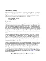
be made in each direction independently. Figure 9.1 shows how reservations for
the RSVP session are enforced on the output interfaces of the routers in the
direction of the session stream.Though the router keeps a stateful database of all
reservations, it is at these interfaces that WFQ,WRED, or both act to implement
the reservation.
www.syngress.com
110_QoS_09 2/13/01 11:50 AM Page 322
www.syngress.com
We also saw in Chapter 8 that RSVP is transparent to non-RSVP enabled
nodes so that they can tunnel over non-RSVP aware networks (as shown in the
Figure). However, notice that no reservations are made in the cloud or at its
egress; therefore, there can be no bandwidth guarantees here.
Enabling RSVP is much easier than trying to explain the mechanics of how
it works. However, even though it is simple to enable, do not be tempted to
enable it carelessly on all interfaces in your router network. It does take planning
to ensure that RSVP reservations do not run rampant and take bandwidth from
other applications.
You will want to refer to Figure 9.1 throughout this section.We will refer-
ence it in relation to enabling RSVP, and to illustrate particular show commands.
Configuring Advanced QoS • Chapter 9 323
Figure 9.1 RSVP on the Network
Client A
(Sender)
10.0.6.2
Client B
(Receiver)
10.0.1.2
Reservations are
enforced on these
interfaces in
direction of flow.
Non-RSVP aware
IP Network
Downstream
10.0.6.0/24
10.0.1.0/24
Router 1
Router 2
Router 3
Router 4
e2/0
10.0.6.1
s5/0:0
10.0.101.6
s4/0/0:0
10.0.101.5
110_QoS_09 2/13/01 11:50 AM Page 323
324 Chapter 9 • Configuring Advanced QoS
Enabling RSVP
Because WRED and WFQ act to implement RSVP reservations on the output
interfaces of routers, RSVP must be enabled on a per interface basis.To do this,
use the ip rsvp bandwidth command in the interface configuration context:
Router1 #config t
Enter configuration commands, one per line. End with CNTL/Z.
Router1 (config)#int s5:0/0
Router1 (config-if)#bandwidth 1152
Router1 (config-if)#ip rsvp bandwidth 768 128
The first argument on the ip rsvp bandwidth command is the total amount
of bandwidth that can be reserved on the interface.The second argument is the
maximum bandwidth of a single reservation.Thus, the interface can set aside no
more than 768 Kbps for RSVP reservations, with each reservation being no
larger than 128 Kbps.
Notice that the bandwidth command was entered first to tell the router the
value of the total link speed. Many serial interfaces will default to 1544 Kbps
unless otherwise specified.This is important since RSVP uses the bandwidth of
the serial interface to calculate how much of the total can be reserved. RSVP
will not allow more than 75 per cent of the total bandwidth to be reserved.
Remember that you have to enable RSVP on each interface that you would
like to participate in RSVP. Specifically, enable it on interfaces on which you
expect QoS implementation mechanisms like WRED and WFQ to act to deliver
QoS.
Verifying Your RSVP Configuration
You can confirm that your RSVP configuration is entered properly with the
show run command, but there are other commands that you will find useful to
monitor the status of RSVP.
With the show ip rsvp installed command, all the current reservations can
be displayed for each interface:
Router1#show ip rsvp installed
RSVP: Ethernet2/0 has no installed reservations
RSVP: Serial5/0:0
BPS To From Protoc DPort Sport Weight Conversation
128K 10.0.1.2 10.0.6.2 TCP 0 0 6 271
64K 10.0.1.3 10.0.6.3 TCP 0 0 12 272
www.syngress.com
110_QoS_09 2/13/01 11:50 AM Page 324
Configuring Advanced QoS • Chapter 9 325
In this example, there are two reservations going out Serial5/0:0 from the
senders 10.0.1.2 and 10.0.1.3 to the receivers 10.0.6.2 and 10.0.6.3 (the second
pair of senders and receivers are not shown in Figure 9.1).The first reservation is
for 128 Kbps, and the second is for 64 Kbps.The weight listed is the weighting
factor used by WFQ.The conversation is the number assigned to that flow.Take a
look at Figure 9.1 again, and remember that since the session flow is towards
Client B from Client A, and because WFQ and WRED work on output inter-
faces, there is no reservation on the Ethernet 2/0, even though the session is
flowing in to the router through this interface.
To see interface specific information, such as how much total bandwidth has
been set aside for RSVP (i/f max) and the amount currently being used (allo-
cated), issue the show ip rsvp interface command:
Router1#show ip rsvp interface
interface allocated i/f max flow max pct UDP IP UDP_IP UDP M/C
Et2/0 0M 7500K 7500K 0 0 2 0 0
Se5/0:0 192K 1152K 1152K 16 0 1 0 0
Sometimes it is helpful to see all neighboring nodes that are participating in
RSVP.To do this, use the show ip rsvp neighbor command:
Router1#show ip rsvp neighbor
Interfac Neighbor Encapsulation
Et2/0 10.0.6.3 RSVP
Et2/0 10.0.6.2 RSVP
Se5/0:0 10.0.101.5 RSVP
This tells us that there are two RSVP neighbors out the Ethernet 2/0 inter-
face and another one out the Se5/0:0 interface.These neighbors can be any
nodes that are currently using RSVP.They could be end-stations (10.0.6.3 and
10.0.6.2) or RSVP participating router interfaces (10.0.101.5).
To display RSVP information such as requests flowing upstream and receiver
and sender information currently in the database, use the following commands,
respectively:
www.syngress.com
110_QoS_09 2/13/01 11:50 AM Page 325
326 Chapter 9 • Configuring Advanced QoS
Router1#show ip rsvp request
To From Pro DPort Sport Next Hop I/F Fi Serv BPS Bytes
10.0.1.2 10.0.6.2 TCP 0 0 10.0.6.2 Et2/0 FF LOAD 128K 64K
10.0.1.3 10.0.6.3 TCP 0 0 10.0.6.3 Et2/0 FF RATE 64K 1K
Router1#show ip rsvp reservation
To From Pro DPort Sport Next Hop I/F Fi Serv BPS Bytes
10.0.1.2 10.0.6.2 TCP 0 0 10.0.101.5 Se5/0 FF LOAD 128K 64K
10.0.1.3 10.0.6.3 TCP 0 0 10.0.101.5 Se5/0 FF RATE 64K 1K
Router1#show ip rsvp sender
To From Pro DPort Sport Prev Hop I/F BPS Bytes
10.0.1.2 10.0.6.2 TCP 0 0 10.0.6.2 Et2/0 128K 1K
10.0.1.3 10.0.6.3 TCP 0 0 10.0.6.3 Et2/0 64K 1K
The request and reservation show commands also indicate the type of service
desired, either controlled-load (LOAD) or guaranteed-rate (RATE).
www.syngress.com
To capture the outputs shown above, a network similar to the one in
Figure 9.1 can be set up in the lab. Because of the lack of RSVP-enabled
clients, a feature called RSVP proxy is used to generate the Send and
Resv messages. RSVP proxy is available on Cisco routers and allows the
manual configuration of reservations. These are statically entered and
remain in place until removed. Because they are not dynamic, it is not
recommended that they be used for anything but testing, since the
bandwidth remains “nailed-up” and cannot be used by packets outside
of the reservation. Nonetheless, with these reservations up, QoS can be
provided to packets matching the criteria set up with the proxy com-
mands. For reference, here are the necessary commands.
Router1:
ip rsvp sender 10.0.1.2 10.0.6.2 TCP 0 0 10.0.6.2
Ethernet2/0 128 1
ip rsvp sender 10.0.1.3 10.0.6.3 TCP 0 0 10.0.6.3
Ethernet2/0 64 1
RSVP Proxy
Continued
110_QoS_09 2/13/01 11:50 AM Page 326
Configuring Advanced QoS • Chapter 9 327
Troubleshooting RSVP
The first step in troubleshooting an RSVP configuration is to use the show com-
mands discussed. A good understanding of the session start-up process is required
in order to determine where things might be going wrong.To help figure it out,
you can use debugging commands.To turn on RSVP debugging, issue the
debug ip rsvp command from the privileged exec command mode (enable
mode). After enabling debugging, check your log with the show log command.
Alternatively, you can enable terminal monitoring (if you are using Telnet) with
terminal monitor to copy debug commands to the terminal window.
WARNING
Debugging is a privileged command that can be frustrating at times. If
there is a lot of output from the debugging, you could swamp the pro-
cessor and your terminal session, essentially locking you out of the
router. If you expect large amounts of output, consider debugging with
an access list. For example, use debug ip rsvp 100 detail, where 100 is
an access list to select the addresses or protocols you are interested in.
www.syngress.com
Router4:
ip rsvp reservation 10.0.1.2 10.0.6.2 TCP 0 0 10.0.1.2
Ethernet0/1 FF LOAD 128 64
ip rsvp reservation 10.0.1.3 10.0.6.3 TCP 0 0 10.0.1.3
Ethernet0/1 FF RATE 64 1
The ip rsvp sender command emulates a sender and generates
RSVP Path packets. The ip rsvp reservation command emulates a
receiver and generates RSVP Resv packets. Refer to Chapter 8 for a
refresher on how these two packet types work to make a reservation,
and see the Cisco documentation for the exact syntax of these com-
mands if you want to use them to test your RSVP network.
110_QoS_09 2/13/01 11:50 AM Page 327
328 Chapter 9 • Configuring Advanced QoS
Enabling, Verifying, and
Troubleshooting Class-Based
Weighted Fair Queuing (CBWFQ)
CBWFQ allows the guarantee of bandwidth to classes defined by criteria such as
protocol, Access Control Lists (ACLs), IP precedence, or input interfaces.
CBWFQ is available on most Cisco router platforms, starting with IOS code ver-
sion 12.0(5)T.
To get up and running with CBWFQ, you first have to determine how many
classes you need in order to categorize all your traffic.You also need to know
what criteria you are going to use to map traffic into those classes, and what
bandwidth guarantees you will give to each class. If you have already classified
your traffic at the edge of the network, IP precedence may the only criterion you
need. If you are configuring a more modest, point-to-point implementation of
CBWFQ, you will probably use extended ACLs to categorize incoming traffic
into classes.
Enabling CBWFQ
There are three major steps in configuring CBWFQ:
1. Defining class maps
2. Creating policy maps
3. Attaching policies to interfaces
Class maps determine what traffic goes into what class and can be used in
one or more policy maps. Policy maps determine how that traffic is handled. But
no QoS is delivered until the policy map is applied to the interfaces. Let us see
how this is done.
Defining Class Maps
The class-map statements in the router configuration determine how traffic is
classified.The configured class must have a name that you can reference later.
Within the class map, you set your match criteria. Consider this example:
router1#config t
Enter configuration commands, one per line. End with CNTL/Z.
router1(config)#class-map Gold
router1(config-cmap)#match access-group name Gold
www.syngress.com
110_QoS_09 2/13/01 11:50 AM Page 328
Configuring Advanced QoS • Chapter 9 329
In this example, we created a class map with the name Gold.This could be a
premium service offered to applications that guarantees a certain bandwidth.
Furthermore, while in the class-map (config-cmap) command mode, we
entered a match criterion, namely, the ACL named Gold.Thus, all traffic that
matches the ACL will be part of the Gold class map.We have used the same
name, Gold, for both the class map and the ACL name for consistency. It is neces-
sary to configure the ACLs if you want the class maps to use them. In this case,
the ACL might be configured like this:
router1(config)#ip access-list extended Gold
router1(config-ext-nacl)#permit ip any any precedence flash-override
An extended access list is used so we can specify a match for any IP packet
with a precedence of 4 (the fourth level of precedence is traditionally given the
name flash-override). If it could not be expected that packets were marked at the
edge of the network with IP precedence, then you would probably use an ACL
that classifies traffic based on criteria like protocol and port number. If you are
not already familiar with Access Control Lists, you should take some time to
learn more about them.They are used frequently in many Cisco router features
and are essential if you want fine control over what kinds of traffic end up in
your QoS classes.
NOTE
In the previous example, we used an access list to specify the traffic. But
if your match criteria are a little simpler, you may be able to match all
your traffic with commands in the class map alone. With IOS 12.0(5)T,
you can match all packets corresponding to a particular protocol with
the match protocol command, or all packets arriving on a particular
interface with the match input-interface command. With more recent
versions of IOS, you can match according to criteria such as source
address, destination address, protocol, IP precedence, and DSCP levels—
all without using ACLs. Furthermore, you can place logical “AND” or
“OR” statements between each of these criteria by specifying the class
map with the class-map match-all or class-map match-any commands,
respectively.
www.syngress.com
110_QoS_09 2/13/01 11:50 AM Page 329
330 Chapter 9 • Configuring Advanced QoS
Now that the Gold class has been configured, we can configure more class
maps the same way:
router1(config)#class-map Silver
router1(config-cmap)#match access-group name Silver
router1(config-cmap)#class-map Bronze
router1(config-cmap)#match access-group name Bronze
The extended access lists would be defined as follows:
router1(config)#ip access-list extended Bronze
router1(config-ext-nacl)#permit ip any any precedence immediate
router1(config-ext-nacl)#ip access-list extended Silver
router1(config-ext-nacl)#permit ip any any precedence flash
This gives us three classes, Gold, Bronze, and Silver, mapped to the IP prece-
dence levels 4, 3, and 2, respectively.
Creating Policies
Now that we have defined class maps, we can continue on to the second step to
create the policy maps that specify the QoS the classes will ultimately have. Let us
configure the policy for the Gold class configured in the last example:
router1(config)#policy-map PPP-T1
router1(config-pmap)#class Gold
router1(config-pmap-c)#bandwidth 216
We have given the name “PPP-T1” to the policy-map.You should use a name
that will be descriptive, such as what kind of circuit bandwidth it was meant to
run on.This leads us into the policy map command context (config-pmap).We
now enter the class that we want to specify parameters for, in this case, Gold.
Under this new context (config-pmap-c), we specify the bandwidth reserved for
this class in Kbps.You can enter the following commands to configure the QoS
the class will be given:
■
bandwidth Bandwidth (in Kbps)
■
queue-limit Maximum queue threshold for tail drop
■
random-detect Enable WRED as drop policy
www.syngress.com
110_QoS_09 2/13/01 11:50 AM Page 330
Configuring Advanced QoS • Chapter 9 331
The bandwidth is the rate guaranteed to this class in Kbps. By default, the sum
of all bandwidth rates for a policy cannot exceed 75 percent of the interface’s total
bandwidth.This leaves room for Layer 2 keepalives, routing updates, and so on.
NOTE
The maximum value that you can allocate to all classes can be changed
from the default value of 75 percent using the max-reserved-bandwidth
command while in the interface configuration mode. Although Cisco dis-
courages changing this value, you can increase it in aggressive situations
if you know the composition of your traffic. It is even possible to raise it
to 100 percent if you create an explicit class for IP precedence levels 6 and
7 (internet and network) and ensure that no other traffic gets marked
into these precedence levels. In the case of routing protocols like EIGRP
and OSPF, leave the router IP precedence set automatically.
You should choose the bandwidth for each class carefully, based on your
needs. Remember that since the bandwidth you give to a class is measured at the
interface, it must be large enough to accommodate Layer 2 overhead.
NOTE
In IOS version 12.1 and later, the bandwidth command for the class can
be entered in Kbps or as a percentage of the total bandwidth. However,
all classes must be configured consistently in either Kbps rates or per-
centages. The exception is for LLQ. The priority class inside LLQ can have
bandwidth specified only in Kbps.
The last two configurable parameters, queue-limit and random-detect, specify
the drop policy for the class. By default, the drop policy is tail drop with a queue
limit of 64 for that class.You may use the queue-limit command to change it to
a value between 1 and 64. A shorter queue will drop packets quicker in times of
congestion.WRED can be configured with the random-detect command.
Additionally the random-detect exponential-weighting-constant command
can be used to adjust how adaptive WRED is to bursts. See the discussion on
WRED in Chapter 8 for an overview and a later section in this chapter for con-
figuration specifics.
www.syngress.com
110_QoS_09 2/13/01 11:50 AM Page 331
332 Chapter 9 • Configuring Advanced QoS
Unclassified traffic, that is, traffic that is not matched into any of the user-
defined classes, gets put into a special class called class-default. This class does not
appear explicitly in the router configuration unless you configure it. By default,
unclassified traffic will be flow-classified and queued by WFQ. However, if you
configure this class specifically, you can give it a bandwidth guarantee too. Let us
configure the default-class:
router1(config)#policy-map PPP-T1
router1(config-pmap)#class class-default
router1(config-pmap-c)#bandwidth 31
www.syngress.com
The treatment of the default class in CBWFQ varies depending on the IOS
revision and platform. This is because of enhancements in the router
code. For IOS releases before 12.1(2)E1 on the 7500 platform and all
other platforms before release 12.1(5), if left unconfigured, the default
class is flow-classified and given best-effort treatment by WFQ. If the
user-defined classes exceed their bandwidth, they will use the non-guar-
anteed bandwidth proportionately among themselves, but at the detri-
ment of the default class. This has the effect in high congestion
situations of dropping default traffic if the link is filled with classified
traffic.
To illustrate this, consider an example of two defined classes.
Class A is guaranteed 20 percent of the bandwidth, and class B is guar-
anteed 10 percent of the bandwidth. The maximum reserved bandwidth
is left at its default value of 75 percent of the link speed. In a congested
situation, after the two classes get their guaranteed bandwidth, the
remaining bandwidth (45 percent) is divided proportionately between
these two classes at a 2:1 ratio. The default class will not receive any
bandwidth if there is enough classified traffic to fill the remaining 45
percent.
After the router code levels listed above, the default class is
treated exactly like the user-defined classes. Considering the same
example, the default class gets a guarantee of 45 percent of the band-
width. After all classes reach their guarantees, the remaining bandwidth
(25 percent) is divided among Class A, Class B, and the default class with
a 20:10:45 weighting, respectively.
Treatment of the Default Class in CBWFQ
Continued
110_QoS_09 2/13/01 11:50 AM Page 332
Configuring Advanced QoS • Chapter 9 333
Instead of being fair-queued, the default class, consisting of unclassified traffic,
will now be guaranteed at least 31 Kbps of bandwidth.
We can thus configure the policy map (PPP-T1) with the other classes we
are interested in so that the entire policy looks as follows in the router’s configu-
ration:
class-map Gold
match access-group Gold
class-map Bronze
match access-group Bronze
class-map Silver
match access-group Silver
!
policy-map PPP-T1
class Gold
bandwidth 216
class Silver
bandwidth 169
class Bronze
bandwidth 108
class class-default
bandwidth 31
!
. . .
!
ip access-list extended Gold
permit ip any any precedence flash-override
ip access-list extended Bronze
permit ip any any precedence immediate
www.syngress.com
To make the earlier code revisions act like the new versions, you
should configure the default class. That is, set the bandwidth statement
in the default-class to the value you want to guarantee to unclassified
traffic. Setting the bandwidth statement for the default class is not
allowed under the newer code, because it is already guaranteed the
remaining bandwidth.
110_QoS_09 2/13/01 11:50 AM Page 333
334 Chapter 9 • Configuring Advanced QoS
ip access-list extended Silver
permit ip any any precedence flash
Attaching Policies to Interfaces
The final step required to enable CBWFQ is to attach the service policy to an
interface:
router1(config)#interface serial 0/0
router1(config-if)#service-policy output PPP-T1
After a service policy is defined, it can be enabled on multiple interfaces,
assuming the interface has enough bandwidth to support all the guarantees. In
contrast to this, only one policy can be attached to a single interface.
Furthermore, after the policy is attached, certain commands relating to queuing
and WRED are disabled, since the policy now controls these functions.
The preceding three-step approach to enabling CBWFQ is a demonstration
of Cisco’s Modular QoS Command Line Interface. It is this modular approach
that allows you not only to modify policies without disturbing interfaces and to
attach policies to multiple interfaces, but also to copy a policy to like routers,
thereby making network-wide configuration of QoS easier.
Verifying Your CBWFQ Configuration
The first step in assuring that your policies are configured correctly is to look at
the configuration with the show running-config command. After that, you can
view a particular policy with the show policy-map command:
router1#show policy-map
Policy Map PPP-T1
Weighted Fair Queueing
Class Gold
Bandwidth 216 (kbps) Max Thresh 64 (packets)
Class Silver
Bandwidth 169 (kbps) Max Thresh 64 (packets)
Class Bronze
Bandwidth 108 (kbps) Max Thresh 64 (packets)
Class class-default
Bandwidth 31 (kbps) Max Thresh 64 (packets)
www.syngress.com
110_QoS_09 2/13/01 11:50 AM Page 334
Configuring Advanced QoS • Chapter 9 335
This shows the configured bandwidth for each class within the policy, and the
maximum threshold for the queue before tail drop is enacted. If you have mul-
tiple policies configured, you can specify the name of the policy with the same
command show policy-map policy-map-name, and even the specific class
within the policy:
router1#show policy-map PPP-T1 class Gold
Class Gold
Bandwidth 216 (kbps) Max Thresh 64 (packets)
To view the statistics of how the policy has been functioning on the inter-
face, use the show policy-map interface command:
router1#show policy-map interface serial 0/0
Serial0/0 output : PPP-T1
Weighted Fair Queueing
Class Gold
Output Queue: Conversation 265
Bandwidth 216 (kbps) Packets Matched 248318 Max Threshold 64
(packets)
(discards/tail drops) 95418/84680
Class Silver
Output Queue: Conversation 266
Bandwidth 169 (kbps) Packets Matched 248305 Max Threshold 64
(packets)
(discards/tail drops) 119558/109829
Class Bronze
Output Queue: Conversation 267
Bandwidth 108 (kbps) Packets Matched 248292 Max Threshold 64
(packets)
(discards/tail drops) 156598/148956
Class class-default
Output Queue: Conversation 268
Bandwidth 31 (kbps) Packets Matched 428362 Max Threshold 64
(packets)
(discards/tail drops) 234720/222514
www.syngress.com
110_QoS_09 2/13/01 11:50 AM Page 335
336 Chapter 9 • Configuring Advanced QoS
You can use this command to see what your class composition is with respect
to the number of packets matched into the classes and the effect of tail drop (or
WRED) on each class.You can always see the overall performance of the inter-
face to which the policy is applied by using the show interface or show queue
command:
router1#show queue serial 0/0
Input queue: 0/75/0 (size/max/drops); Total output drops: 778978
Queueing strategy: weighted fair
Output queue: 0/1000/64/778978 (size/max total/threshold/drops)
Conversations 0/4/256 (active/max active/max total)
Reserved Conversations 4/4 (allocated/max allocated)
This shows the current state of the input and output queues, including cur-
rent size, maximum size, and number of drops. It also shows the specifics of
WFQ. As usual, the total number of conversations is 256. However, note that
there are four reserved conversations corresponding to the four classes (including
the default class) configured on the interface by the policy.
Troubleshooting CBWFQ
Because CBWFQ is not a network QoS mechanism per se, but rather a queuing
mechanism that operates individually on a router, troubleshooting faulty configu-
rations always starts with the router in question. If you have problems with
CBWFQ, the first step is to use the show commands to verify that the policies
are configured properly and attached to the appropriate interfaces.
Usually, the ultimate question with CBWFQ is,“Is it working?”Though you
may be able to see from commands like show policy interface that it does
seem to be working, the real test lies in your applications’ performance. Are they
getting the bandwidth guarantees that you expect? This is not always easy to
answer. Besides the router show commands, you may want to consider doing
some formalized testing of your applications in congestion situations, with and
without the policy, to determine the effect.You can also use tools such as packet
decoders and packet generators to emulate a production environment. A product
such as Cisco Internetwork Performance Monitor (IPM) can also be of use in
monitoring the status of your network.
www.syngress.com
110_QoS_09 2/13/01 11:50 AM Page 336
Configuring Advanced QoS • Chapter 9 337
Configuring, Verifying, and
Troubleshooting Low Latency
Queuing (LLQ)
As discussed in chapter 8, low latency queuing (LLQ) extends CBWFQ to
include the option of creating a strict priority queue. Strict priority queuing
delivers low latency transmission to constant bit rate (CBR) applications such as
voice. It has wide platform availability starting with IOS release 12.0(7)T.
Configuring LLQ
After you understand how to configure CBWFQ, configuring LLQ is easy. A low
latency class is configured very much like other user-defined classes. Let us add to
the example in the last section and configure another class with a guarantee of
bandwidth and low latency transmission.We first must define a class map:
router1(config)#class-map Platinum
router1(config-cmap)#match access-group name Platinum
Again, we use an ACL to match traffic into this class. If you imagine that, like
the other classes in our example, we already have marked traffic into granular IP
precedence levels, then our access list for this class might be configured like this:
router1(config)#ip access-list extended Platinum
router1(config-ext-nacl)#permit ip any any precedence critical
In this configuration, incoming packets matching IP precedence 5 (critical)
are mapped into this priority class. IP precedence 5 is the normal level for VoIP
traffic, which is what we can imagine would comprise this class exclusively.
Now we must add the class to a policy map:
router1(config)#policy-map PPP-T1
router1(config-pmap)#class Platinum
router1(config-pmap-c)#priority 384
This is where we denote that this class should have low latency queuing. By
using the priority command, we have specified that the Platinum class will
receive priority treatment in an exhaustive queue.The priority command is used
instead of the bandwidth command to specify the guarantee of bandwidth.This
is the only major difference in configuring LLQ.
www.syngress.com
110_QoS_09 2/13/01 11:50 AM Page 337
338 Chapter 9 • Configuring Advanced QoS
After using the priority command on a class within a policy, the command to
enable WRED, random-detect, is disabled.The priority queue does not support
WRED because of the nature of the priority queue and the type of traffic that
should be placed in it, notably voice.Voice packets are UDP-based and therefore
not responsive to congestion notifications through packet drops. Furthermore,
drops do not occur at the priority queue unless the bandwidth set with the pri-
ority command has been exceeded and there is congestion on the line. In the
event of congestion, all packets in excess of the guaranteed bandwidth are
dropped from the priority queue.
Verifying Your LLQ Configuration
We use the same commands to examine the function of LLQ as we used for
CBWFQ.The output for the priority class does look a little different. Notice that
the class shows that it is being given strict priority treatment:
router1#show policy PPP-T1 class Platinum
Class Platinum
Strict Priority
Bandwidth 384 (kbps) Max Threshold 64 (packets)
Similarly, the policy statistics for the interface shows strict priority for the
Platinum class:
router1#show policy-map interface serial 0/0
Serial0/0 output : PPP-T1
Weighted Fair Queueing
Class Platinum
Strict Priority
Output Queue: Conversation 264
Bandwidth 384 (kbps) Packets Matched 0 248368 Max Threshold 64
(packets)
(discards/tail drops) 0/0
Class Gold
Output Queue: Conversation 265
Bandwidth 216 (kbps) Packets Matched 248318 Max Threshold 64
(packets)
(discards/tail drops) 95418/84680
Class Silver
www.syngress.com
110_QoS_09 2/13/01 11:50 AM Page 338
Configuring Advanced QoS • Chapter 9 339
Output Queue: Conversation 266
Bandwidth 169 (kbps) Packets Matched 248305 Max Threshold 64
(packets)
(discards/tail drops) 119558/109829
Class Bronze
Output Queue: Conversation 267
Bandwidth 108 (kbps) Packets Matched 248292 Max Threshold 64
(packets)
(discards/tail drops) 156598/148956
Class class-default
Output Queue: Conversation 268
Bandwidth 31 (kbps) Packets Matched 428362 Max Threshold 64
(packets)
(discards/tail drops) 234720/222514
Troubleshooting LLQ
Like CBWFQ, troubleshooting LLQ starts with knowing what to expect from
the router configuration and how your applications are performing. If it seems
that your applications are not getting low latency priority queuing, you can use
the debug priority command to troubleshoot.This command will notify you of
drops in the priority queue, which should happen only when the subscribed
bandwidth has been exceeded and the link is congested. Here is a sample output
when a T1 link was filled to capacity and the priority queue was overflowing:
Jan 30 22:42:45: WFQ: dropping a packet from the priority queue 0
Jan 30 22:42:45: WFQ: dropping a packet from the priority queue 0
Jan 30 22:42:45: WFQ: dropping a packet from the priority queue 0
Jan 30 22:42:45: WFQ: dropping a packet from the priority queue 0
Jan 30 22:42:45: WFQ: dropping a packet from the priority queue 0
Jan 30 22:42:46: WFQ: dropping a packet from the priority queue 0
Each packet that is dropped is logged.This debug command also works with
other priority queuing schemes besides LLQ, such as RTP priority queuing.
www.syngress.com
110_QoS_09 2/13/01 11:50 AM Page 339
340 Chapter 9 • Configuring Advanced QoS
Configuring, Verifying, and
Troubleshooting Weighted
Random Early Detection (WRED)
In the last chapter, we saw that WRED is a congestion avoidance mechanism that
takes advantage of TCP’s congestion control by randomly dropping packets from
flows before congestion occurs. It gives differential treatment to packets of dif-
ferent IP precedence levels by assigning different drop thresholds. Because of this,
and because it can be enabled on a variety of interfaces, it is often used in high-
speed backbones where packets are marked with IP precedence at the edge of the
network. It is not necessary to have packets marked with different levels of IP
precedence for WRED to function, but without differing levels of IP precedence,
you are using regular RED, because all packets of a given weight (all packets have
a weight of zero, by default) are treated equally.
Configuring WRED
To enable WRED on an interface, use the random-detect command while in
interface configuration mode:
router1(config)#interface serial 0/0
router1(config-if)#random-detect
This is the typical way to configure WRED on an interface.The exception is,
as we saw in a previous section, for CBWFQ policies. In this case, the random-
detect command is issued in the policy itself, not the interface.
Using the random-detect command is all that is normally necessary to enable
WRED on an interface.The default operation of WRED has been optimized for
typical use. However, you can modify WRED from its default behavior in a
couple of ways, as we will demonstrate.
The average queue length is the moving average used in the WRED algo-
rithm to determine with what probability to drop packets (see chapter 8 for
more information). Although Cisco does not recommend it, the weighting factor
of this average can be changed from the default (9) to make WRED more or less
adaptive to traffic bursts.To change this weighting factor, perform the following
command while in interface configuration mode:
router1(config)#interface serial 0/0
router1(config-if)#random-detect exponential-weighting-constant 10
www.syngress.com
110_QoS_09 2/13/01 11:50 AM Page 340
Configuring Advanced QoS • Chapter 9 341
A higher factor will make the average queue length “heavier” and more resis-
tant to changes in traffic speed, whereas a lower factor will make the queue
length “lighter” and more sensitive to traffic changes. If the value is too high, the
algorithm may not be reactive to congestion situations. If the value is too low, a
burst of packets may be dropped unnecessarily.
Another aspect of WRED that you can configure away from the defaults is
how each IP precedence level is weighted.Again, the default values are usually
fine, but you can modify the configuration if you need to. By using the
random-detect precedence command, you can set the following values for
each precedence level:
■
Minimum threshold
■
Maximum threshold
■
Mark probability denominator
Table 9.1
Default WRED and DWRED Threshold Values
WRED Threshold Values DWRED Threshold Values
IP Precedence Minimum Maximum Minimum Maximum
0 20 40 95 190
1 22 40 106 190
2 24 40 117 190
3 26 40 128 190
4 28 40 139 190
5 31 40 150 190
6 33 40 161 190
7 35 40 172 190
RSVP 37 40 N/A N/A
Table 9.1 shows the default values of the minimum and maximum thresholds
for each precedence.The minimum threshold for IP precedence 0 is one half the
maximum.The value of the minimum threshold for the remaining precedences
falls between half the maximum threshold and the maximum threshold at evenly
spaced intervals.The mark probability denominator is the fraction of packets dropped
when the average queue depth is at the maximum threshold. By default, this
value is set to 10 for all precedences.This means that when the average queue is
at the maximum threshold, one out of every 10 packets is dropped. Over this
maximum, all packets are dropped.
www.syngress.com
110_QoS_09 2/13/01 11:50 AM Page 341
342 Chapter 9 • Configuring Advanced QoS
To change these values, use the following syntax while in interface configura-
tion mode:
random-detect precedence precedence min-threshold max-threshold mark-
prob-denominator
This configuration can be repeated for each precedence level. If the values are
configured to be the same for each precedence,WRED essentially becomes RED
(unweighted).
www.syngress.com
Flow-based WRED (FRED) was developed to overcome the problem
occurring when non-adaptive flows such as UDP were taking bandwidth
away from congestion-responsive flows like TCP. The problem occurs
when the average queue depth rises above the maximum threshold for
WRED. When this happens, packets are dropped across all flows, which
discriminates unfairly against smaller congestion-responsive flows. FRED
works by categorizing incoming data into flows, keeping track of the
state of these flows, and dropping packets from non-responsive flows
when they exceed a multiple of their average flow depth. In this way,
FRED ensures that packets that reduce their transmission because of
WRED packet drops are protected from flows that do not respond to
WRED packet drops. It also guarantees that a non-responsive flow will
not monopolize the entire link.
To enable FRED, after configuring WRED on the interface, use the
random-detect flow command. You can change the default behavior
by modifying the flow threshold multiplier and the maximum flow count
using the random-detect flow average-depth-factor and random-
detect flow count commands, respectively. By default, the flow
threshold multiplier is 4, whereas the maximum flow count is 256.
Increasing the flow threshold multiplier will configure FRED to tolerate
higher amounts of non-responsive traffic.
Flow-Based WRED
110_QoS_09 2/13/01 11:50 AM Page 342
Configuring Advanced QoS • Chapter 9 343
Verifying Your WRED Configuration
After enabling WRED, check the configured parameters and the number of drops
per class (IP precedence) using the show queueing random-detect command:
router2#show queueing random-detect
Current random-detect configuration:
Serial5/0:0
Queueing strategy: random early detection (WRED)
Exp-weight-constant: 9 (1/512)
Mean queue depth: 0
Class Random drop Tail drop Minimum Maximum Mark
pkts/bytes pkts/bytes threshold threshold probability
0 4914/560382 18964/2161896 20 40 1/10
1 4786/545604 18834/2147076 22 40 1/10
2 4705/536370 18853/2149242 24 40 1/10
3 4700/535800 18938/2158932 26 40 1/10
4 4612/525768 18830/2146620 28 40 1/10
5 4543/517902 18857/2149698 31 40 1/10
6 4494/512282 18928/2157622 33 40 1/10
7 4380/499320 18851/2149014 35 40 1/10
rsvp 0/0 0/0 37 40 1/10
This provides good information on what kind of traffic, with respect to IP
precedence (or Class), is flowing through the router, and what kind of drop treat-
ment it is getting—random drop or tail drop.We can see from this output that
each IP precedence level (0 to 7) dropped approximately the same number of
packets. For congestion notification responsive flows such as TCP traffic, you
should not see a lot of tail drop.Tail drop occurs when the upper threshold has
been exceeded.When this occurs, packets are dropped wholesale. In this example,
there is a high amount of tail drop because the traffic was created with a packet
generator that did not throttle down when packets were dropped.
The same information can be shown a little differently on the VIP-based RSP
platform for DWRED by using the show interfaces [interface-type interface-
number] random-detect command:
router3#show queueing random-detect
Current random-detect configuration:
www.syngress.com
110_QoS_09 2/13/01 11:50 AM Page 343
344 Chapter 9 • Configuring Advanced QoS
Serial4/0/0:0
Queueing strategy: fifo
Packet drop strategy: VIP-based random early detection (DWRED)
Exp-weight-constant: 9 (1/512)
Mean queue depth: 192
Queue size: 194 Maximum available buffers: 384
Output packets: 150838 WRED drops: 10434 No buffer: 0
Class Random Tail Minimum Maximum Mark Output
drop drop threshold threshold probability Packets
0 1067 543 96 192 1/10 21456
1 0 0 108 192 1/10 0
2 1054 546 120 192 1/10 21412
3 1049 535 132 192 1/10 21428
4 1042 530 144 192 1/10 21439
5 836 517 156 192 1/10 21658
6 831 531 168 192 1/10 21649
7 808 545 180 192 1/10 21658
Here we can see the number of packets of each precedence that were output
from the interface, and the number of drops, both random and tail drop.The
number of packets sent was approximately equal for each class, except that there
were no packets sent with an IP precedence of 1.
If CBWFQ is configured with WRED, these commands will not work to
show WRED statistics; however, the show policy-map interface command
includes WRED information for each class.Take a look at the following output,
paying special attention to the “random-detect” information:
router3#show policy int s4/0/0:0
Serial4/0/0:0
service-policy output: PPP-T1
queue stats for all priority classes:
queue size 0, queue limit 96
packets output 22418, packet drops 0
www.syngress.com
110_QoS_09 2/13/01 11:50 AM Page 344
Configuring Advanced QoS • Chapter 9 345
tail/random drops 0, no buffer drops 0, other drops 0
class-map: Network (match-all)
22751 packets, 11375500 bytes
30 second offered rate 203000 bps, drop rate 0 bps
match: access-group name Network
queue size 0, queue limit 84
packets output 22417, packet drops 1
tail/random drops 1, no buffer drops 0, other drops 0
bandwidth: kbps 338, weight 29
random-detect:
Exp-weight-constant: 10 (1/1024)
Mean queue depth: 0
Class Random Tail Minimum Maximum Mark Output
drop drop threshold threshold probability packets
0 0 0 21 42 1/10 0
1 0 0 23 42 1/10 0
2 0 0 25 42 1/10 0
3 0 0 27 42 1/10 0
4 0 0 29 42 1/10 0
5 0 0 31 42 1/10 0
6 0 0 33 42 1/10 0
7 0 1 35 42 1/10 22417
class-map: Internet (match-all)
22751 packets, 11375500 bytes
30 second offered rate 203000 bps, drop rate 0 bps
match: access-group name Internet
queue size 0, queue limit 69
packets output 22099, packet drops 319
tail/random drops 319, no buffer drops 0, other drops 0
bandwidth: kbps 277, weight 24
random-detect:
Exp-weight-constant: 10 (1/1024)
Mean queue depth: 0
www.syngress.com
110_QoS_09 2/13/01 11:50 AM Page 345