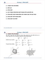
cơ học vật liệu -combined loads & transformations
Bạn đang xem bản rút gọn của tài liệu. Xem và tải ngay bản đầy đủ của tài liệu tại đây (20.13 MB, 299 trang )
To the Instructor iv
1 Stress 1
2 Strain 73
3 Mechanical Properties of Materials 92
4 Axial Load 122
5 Torsion 214
6 Bending 329
7 Transverse Shear 472
8 Combined Loadings 532
9 Stress Transformation 619
10 Strain Transformation 738
11 Design of Beams and Shafts 830
12 Deflection of Beams and Shafts 883
13 Buckling of Columns 1038
14 Energy Methods 1159
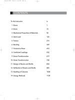
CONTENTS
FM_TOC 46060 6/22/10 11:26 AM Page iii
532
© 2010 Pearson Education, Inc., Upper Saddle River, NJ. All rights reserved.This material is protected under all copyright laws as they currently
exist. No portion of this material may be reproduced, in any form or by any means, without permission in writing from the publisher.
Ans.t = 0.0188 m = 18.8 mm
s
allow
=
p r
2 t
;
12(10
6
) =
300(10
3
)(1.5)
2 t
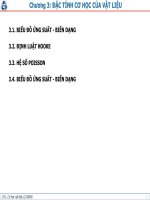
8–1. A spherical gas tank has an inner radius of
If it is subjected to an internal pressure of
determine its required thickness if the maximum normal
stress is not to exceed 12 MPa.
p = 300 kPa,
r = 1.5 m.
Ans.r
o
= 75 in. + 0.5 in. = 75.5 in.
r
i
= 75 in.
s
allow
=
p r
2 t
;
15(10
3
) =
200 r
i
2(0.5)
8–2. A pressurized spherical tank is to be made of
0.5-in thick steel. If it is subjected to an internal pressure
of determine its outer radius if the maximum
normal stress is not to exceed 15 ksi.
p = 200 psi,
Case (a):
Ans.
Ans.
Case (b):
Ans.
Ans.s
2
=
pr
2t
;
s
2
=
65(4)
2(0.25)
= 520 psi
s
1
=
pr
t
;
s
1
=
65(4)
0.25
= 1.04 ksi
s
2
= 0
s
1
=
pr
t
;
s
1
=
65(4)
0.25
= 1.04 ksi
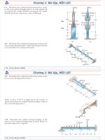
8–3. The thin-walled cylinder can be supported in one of
two ways as shown. Determine the state of stress in the wall
of the cylinder for both cases if the piston P causes the
internal pressure to be 65 psi. The wall has a thickness of
0.25 in. and the inner diameter of the cylinder is 8 in.
P
(
a
)(
b
)
P
8 in. 8 in.
08 Solutions 46060 5/28/10 8:34 AM Page 532
533
© 2010 Pearson Education, Inc., Upper Saddle River, NJ. All rights reserved.This material is protected under all copyright laws as they currently
exist. No portion of this material may be reproduced, in any form or by any means, without permission in writing from the publisher.
Normal Stress: Since , thin-wall analysis is valid. For the
spherical tank’s wall,
Ans.
Referring to the free-body diagram shown in Fig. a,
.Thus,
The normal stress developed in each bolt is then
Ans.s
b
=
P
b
A
b
=
35.56
A
10
3
B
p
p
4
A
0.025
2
B
= 228 MPa
P
b
= 35.56
A
10
3
B
p N
+
c
©F
y
= 0;
32p
A
10
6
B
- 450P
b
- 450P
b
= 0
P = pA = 2
A
10
6
B
c
p
4
A
8
2
B
d= 32p
A
10
6
B
N
s =
pr
2t
=
2(4)
2(0.03)
= 133 MPa
r
t
=
4
0.03
= 133.33 7 10
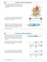
•8–5. Thesphericalgas tankisfabricated byboltingtogether
two hemispherical thin shells of thickness 30 mm. If the gas
contained in the tank is under a gauge pressure of 2 MPa,
determine the normal stress developed in the wall of the tank
and in each of the bolts.The tank has an inner diameter of 8 m
and is sealed with 900 bolts each 25 mm in diameter.
Hoop Stress for Cylindrical Vessels: Since , then thin wall
analysis can be used.Applying Eq. 8–1
Ans.
Longitudinal Stress for Cylindrical Vessels: Applying Eq. 8–2
Ans.s
2
=
pr
2t
=
90(11)
2(0.25)
= 1980 psi = 1.98 ksi
s
1
=
pr
t
=
90(11)
0.25
= 3960 psi = 3.96 ksi
r
t
=
11
0.25
= 44 7 10
*8–4. The tank of the air compressor is subjected to an
internal pressure of 90 psi. If the internal diameter of
the tank is 22 in., and the wall thickness is 0.25 in.,
determine the stress components acting at point A. Draw a
volume element of the material at this point, and show the
results on the element.
A
08 Solutions 46060 5/28/10 8:34 AM Page 533
534
© 2010 Pearson Education, Inc., Upper Saddle River, NJ. All rights reserved.This material is protected under all copyright laws as they currently
exist. No portion of this material may be reproduced, in any form or by any means, without permission in writing from the publisher.
Normal Stress: For the spherical tank’s wall,
Ans.
Since , thin-wall analysis is valid.
Referring to the free-body diagram shown in Fig. a,
.Thus,
(1)
The allowable tensile force for each bolt is
Substituting this result into Eq. (1),
Ans.n =
32p
A
10
6
B
39.0625p
A
10
3
B
= 819.2 = 820
(P
b
)
allow
= s
allow
A
b
= 250
A
10
6
B
c
p
4
A
0.025
2
B
d= 39.0625
A
10
3
B
pN
n =
32p
A
10
6
B
(P
b
)
allow
+
c
©F
y
= 0;
32p
A
10
6
B
-
n
2
(P
b
)
allow
-
n
2
(P
b
)
allow
= 0
P = pA = 2
A
10
6
B
c
p
4
A
8
2
B
d= 32p
A
10
6
B
N
r
t
=
4
0.02667
= 150 7 10
t = 0.02667 m = 26.7 mm
150
A
10
6
B
=
2
A
10
6
B
(4)
2t
s
allow
=
pr
2t
8–6. The spherical gas tank is fabricated by bolting
together two hemispherical thin shells. If the 8-m inner
diameter tank is to be designed to withstand a gauge pressure
of 2 MPa, determine the minimum wall thickness of the
tank and the minimum number of 25-mm diameter bolts
that must be used to seal it.The tank and the bolts are made
from material having an allowable normal stress of 150 MPa
and 250 MPa, respectively.
08 Solutions 46060 5/28/10 8:34 AM Page 534
535
© 2010 Pearson Education, Inc., Upper Saddle River, NJ. All rights reserved.This material is protected under all copyright laws as they currently
exist. No portion of this material may be reproduced, in any form or by any means, without permission in writing from the publisher.
a) Ans.
b)
Ans.
c) From FBD(a)
Ans.(t
avg
)
b
=
F
b
A
-
25312.5
p
4
(0.01)
2
= 322 MPa
F
b
= 25.3 kN
+
c
©F
y
= 0;
F
b
- 79.1(10
6
)[(0.008)(0.04)] = 0
s
1
¿=79.1 MPa
126.56 (10
6
)(0.05)(0.008) = s
1
¿(2)(0.04)(0.008)
s
1
=
pr
t
=
1.35(10
6
)(0.75)
0.008
= 126.56(10
6
) = 127 MPa
8–7. A boiler is constructed of 8-mm thick steel plates that
are fastened together at their ends using a butt joint
consisting of two 8-mm cover plates and rivets having a
diameter of 10 mm and spaced 50 mm apart as shown. If the
steam pressure in the boiler is 1.35 MPa, determine (a) the
circumferential stress in the boiler’s plate apart from
the seam,(b)the circumferential stress in the outer cover plate
along the rivet line a–a,and (c) the shear stress in the rivets.
a
8 mm
50 mm
a
0.75 m
08 Solutions 46060 5/28/10 8:34 AM Page 535
536
© 2010 Pearson Education, Inc., Upper Saddle River, NJ. All rights reserved.This material is protected under all copyright laws as they currently
exist. No portion of this material may be reproduced, in any form or by any means, without permission in writing from the publisher.
Normal Stress: For the cylindrical portion of the tank, the hoop stress is twice as
large as the longitudinal stress.
Ans.
For the hemispherical cap,
Ans.
Since , thin-wall analysis is valid.
Referring to the free-body diagram of the per meter length of the cylindrical
portion, Fig. a, where , we have
(1)
The allowable tensile force for each bolt is
Substituting this result into Eq. (1),
Ans.n
c
= 48.89 = 49 bolts>meter
(P
b
)
allow
= s
allow
A
b
= 250
A
10
6
B
c
p
4
A
0.025
2
B
d= 122.72
A
10
3
B
N
n
c
=
6
A
10
6
B
(P
b
)
allow
+
c
©F
y
= 0;
12
A
10
6
B
- n
c
(P
b
)
allow
- n
c
(P
b
)
allow
= 0
P = pA = 3
A
10
6
B
[4(1)] = 12
A
10
6
B
N
r
t
6 10
t
s
= 0.02 m = 20 mm
s
allow
=
pr
t
;
150
A
10
6
B
=
3
A
10
6
B
(2)
2t
s
t
c
= 0.04 m = 40 mm
s
allow
=
pr
t
;
150
A
10
6
B
=
3
A
10
6
B
(2)
t
c
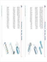
*8–8. The gas storage tank is fabricated by bolting together
two half cylindrical thin shells and two hemispherical shells
as shown. If the tank is designed to withstand a pressure
of 3 MPa, determine the required minimum thickness of
the cylindrical and hemispherical shells and the minimum
required number of longitudinal bolts per meter length at
each side of the cylindrical shell. The tank and the 25 mm
diameter bolts are made from material having an allowable
normal stress of 150 MPa and 250 MPa, respectively. The
tank has an inner diameter of 4 m.
08 Solutions 46060 5/28/10 8:34 AM Page 536
537
© 2010 Pearson Education, Inc., Upper Saddle River, NJ. All rights reserved.This material is protected under all copyright laws as they currently
exist. No portion of this material may be reproduced, in any form or by any means, without permission in writing from the publisher.
Normal Stress: For the cylindrical portion of the tank, the hoop stress is twice as
large as the longitudinal stress.
Ans.
For the hemispherical cap,
Ans.
Since , thin-wall analysis is valid.
The allowable tensile force for each bolt is
Referring to the free-body diagram of the hemispherical cap, Fig. b, where
,
(1)
Substituting this result into Eq. (1),
Ans.n
s
= 307.2 = 308 bolts
n
s
=
12p
A
10
6
B
(P
b
)
allow
:
+
©F
x
= 0;
12p
A
10
6
B
-
n
s
2
(P
b
)
allow
-
n
s
2
(P
b
)
allow
= 0
P = pA = 3
A
10
6
B
c
p
4
A
4
2
B
d= 12p
A
10
6
B
N
(P
b
)
allow
= s
allow
A
b
= 250
A
10
6
B
c
p
4
A
0.025
2
B
d= 122.72
A
10
3
B
N
r
t
6 10
t
s
= 0.02 m = 20 mm
s
allow
=
pr
t
;
150
A
10
6
B
=
3
A
10
6
B
(2)
2t
s
t
c
= 0.04 m = 40 mm
s
allow
=
pr
t
;
150
A
10
6
B
=
3
A
10
6
B
(2)
t
c
•8–9. The gas storage tank is fabricated by bolting together
two half cylindrical thin shells and two hemispherical shells
as shown. If the tank is designed to withstand a pressure of
3 MPa, determine the required minimum thickness of the
cylindrical and hemispherical shells and the minimum
required number of bolts for each hemispherical cap. The
tank and the 25 mm diameter bolts are made from material
having an allowable normal stress of 150 MPa and 250 MPa,
respectively.The tank has an inner diameter of 4 m.
08 Solutions 46060 5/28/10 8:34 AM Page 537
538
© 2010 Pearson Education, Inc., Upper Saddle River, NJ. All rights reserved.This material is protected under all copyright laws as they currently
exist. No portion of this material may be reproduced, in any form or by any means, without permission in writing from the publisher.
Ans.
Ans.s
b
=
F
A
b
=
432
p
4
(0.25)
2
= 8801 psi = 8.80 ksi
s
h
=
F
A
h
=
432
0.5(2)
= 432 psi
©F = 0;
864 - 2F = 0; F = 432 lb
F
R
= 2(36)(12) = 864 lb
8–11. The staves or vertical members of the wooden tank
are held together using semicircular hoops having a
thickness of 0.5 in. and a width of 2 in.Determine the normal
stress in hoop AB if the tank is subjected to an internal
gauge pressure of 2 psi and this loading is transmitted
directly to the hoops.Also, if 0.25-in diameter bolts are used
to connect each hoop together, determine the tensile stress
in each bolt at A and B. Assume hoop AB supports the
pressure loading within a 12-in. length of the tank as shown.
Equilibrium for the steel Hoop: From the FBD
Hoop Stress for the Steel Hoop:
Ans. s = 33.3 in.
12(10
3
) =
72.0s
0.2
s
1
= s
allow
=
P
A
:
+
©F
x
= 0;
2P - 4(36s) = 0
P = 72.0s
8–10. A wood pipe having an inner diameter of 3 ft is
bound together using steel hoops each having a cross-
sectional area of If the allowable stress for the hoops
is determine their maximum spacing s along
the section of pipe so that the pipe can resist an internal
gauge pressure of 4 psi. Assume each hoop supports the
pressure loading acting along the length s of the pipe.
s
allow
= 12 ksi,
0.2 in
2
.
s
ss
4 psi
4 psi
6 in.
12 in.
18 in.
12 in.
6 in.
AB
08 Solutions 46060 5/28/10 8:34 AM Page 538
539
© 2010 Pearson Education, Inc., Upper Saddle River, NJ. All rights reserved.This material is protected under all copyright laws as they currently
exist. No portion of this material may be reproduced, in any form or by any means, without permission in writing from the publisher.
Compatibility: Since the band is fixed to a rigid cylinder (it does not deform under
load), then
Ans. = 10(9.60)
A
10
-6
B
28.0
A
10
3
B
= 2.69 ksi
s
c
= 10aE
2p
E
s
c
= 10a
L
2p
0
(1 - cos 2u)du
2pr
E
a
P
A
b= 20ar
L
2p
0
sin
2
udu
however,
P
A
= s
c
P(2pr)
AE
-
L
2p
0
a¢Trdu = 0
d
F
- d
T
= 0
•8–13. The 304 stainless steel band initially fits snugly around
the smooth rigid cylinder. If the band is then subjected to a
nonlinear temperature drop of where is
in radians, determine the circumferential stress in the band.
u¢T = 20 sin
2
u °F,
Normal Pressure: Vertical force equilibrium for FBD(a).
The Friction Force: Applying friction formula
a) The Required Torque: In order to initiate rotation of the two hemispheres
relative to each other, the torque must overcome the moment produced by the
friction force about the center of the sphere.
Ans.
b) The Required Vertical Force: In order to just pull the two hemispheres apart, the
vertical force P must overcome the normal force.
Ans.
c) The Required Horizontal Force: In order to just cause the two hemispheres to
slide relative to each other, the horizontal force F must overcome the friction force.
Ans.F = F
f
= 2880p = 9048 lb = 9.05 kip
P = N = 5760p = 18096 lb = 18.1 kip
T = F
f
r = 2880p(2 + 0.125>12) = 18190 lb
#
ft = 18.2 kip
#
ft
F
f
= m
s
N = 0.5(5760p) = 2880p lb
+
c
©F
y
= 0;
10
C
p(24
2
)
D
- N = 0
N = 5760p lb
*8–12. Two hemispheres having an inner radius of 2 ft and
wall thickness of 0.25 in. are fitted together, and the inside
gauge pressure is reduced to psi. If the coefficient
of static friction is between the hemispheres,
determine (a) the torque T needed to initiate the rotation
of the top hemisphere relative to the bottom one, (b) the
vertical force needed to pull the top hemisphere off
the bottom one, and (c) the horizontal force needed to slide
the top hemisphere off the bottom one.
m
s
= 0.5
-10
2 ft
0.25 in.
10 in.
u
in.
1 in.
1
64
08 Solutions 46060 5/28/10 8:34 AM Page 539
540
© 2010 Pearson Education, Inc., Upper Saddle River, NJ. All rights reserved.This material is protected under all copyright laws as they currently
exist. No portion of this material may be reproduced, in any form or by any means, without permission in writing from the publisher.
Equilibrium for the Ring: Form the FBD
Hoop Stress and Strain for the Ring:
Using Hooke’s Law
[1]
However, .
Then, from Eq. [1]
Ans.dr
i
=
pr
i
2
E(r
s
- r
i
)
dr
i
r
i
=
pr
i
E(r
s
- r
i
)
e
1
=
2p(r
i
)
1
- 2pr
i
2pr
=
(r
i
)
1
- r
i
r
i
=
dr
i
r
i
e
1
=
s
1
E
=
pr
i
E(r
s
- r
i
)
s
1
=
P
A
=
pr
i
w
(r
s
- r
i
)w
=
pr
i
r
s
- r
i
:
+
©F
x
= 0;
2P - 2pr
i
w = 0
P = pr
i
w
8–14. The ring, having the dimensions shown, is placed
over a flexible membrane which is pumped up with a
pressure p. Determine the change in the internal radius of
the ring after this pressure is applied. The modulus of
elasticity for the ring is E.
p
r
o
w
r
i
08 Solutions 46060 5/28/10 8:34 AM Page 540
541
© 2010 Pearson Education, Inc., Upper Saddle River, NJ. All rights reserved.This material is protected under all copyright laws as they currently
exist. No portion of this material may be reproduced, in any form or by any means, without permission in writing from the publisher.
Equilibrium for the Ring: From the FBD
Hoop Stress and Strain for the Ring:
Using Hooke’s law
[1]
However, .
Then, from Eq. [1]
Compatibility: The pressure between the rings requires
[2]
From the result obtained above
Substitute into Eq. [2]
Ans. p =
E(r
2
- r
3
)
r
2
2
r
2
- r
1
+
r
3
2
r
4
- r
3
pr
2
2
E(r
2
- r
1
)
+
pr
3
2
E(r
4
- r
3
)
= r
2
- r
3
dr
2
=
pr
2
2
E(r
2
- r
1
)
dr
3
=
pr
3
2
E(r
4
- r
3
)
dr
2
+ dr
3
= r
2
- r
3
dr
i
=
pr
i
2
E(r
o
- r
i
)
dr
i
r
i
=
pr
i
E(r
o
- r
i
)
e
1
=
2p(r
i
)
1
- 2pr
i
2pr
=
(r
i
)
1
- r
i
r
i
=
dr
i
r
i
e
1
=
s
1
E
=
pr
i
E(r
o
- r
i
)
s
1
=
P
A
=
pr
i
w
(r
o
- r
i
)w
=
pr
i
r
o
- r
i
:
+
©F
x
= 0;
2P - 2pr
i
w = 0
P = pr
i
w
8–15. The inner ring A has an inner radius and outer
radius . Before heating, the outer ring B has an inner
radius and an outer radius , and . If the outer ring
is heated and then fitted over the inner ring, determine the
pressure between the two rings when ring B reaches the
temperature of the inner ring.The material has a modulus of
elasticity of E and a coefficient of thermal expansion of .a
r
2
7 r
3
r
4
r
3
r
2
r
1
r
1
r
2
r
3
A
B
r
4
08 Solutions 46060 5/28/10 8:34 AM Page 541
542
© 2010 Pearson Education, Inc., Upper Saddle River, NJ. All rights reserved.This material is protected under all copyright laws as they currently
exist. No portion of this material may be reproduced, in any form or by any means, without permission in writing from the publisher.
Normal Stress:
Equilibrium: We will consider the triangular element cut from the strip
shown in Fig. a. Here,
s
l
= s
2
=
pr
2t
=
p(d>2)
2t
=
pd
4t
s
h
= s
1
=
pr
t
=
p(d>2)
t
=
pd
2t
*8–16. The cylindrical tank is fabricated by welding a
strip of thin plate helically, making an angle with the
longitudinal axis of the tank. If the strip has a width w and
thickness t, and the gas within the tank of diameter d is
pressured to p, show that the normal stress developed along
the strip is given by .s
u
= (pd>8t)(3 - cos 2u)
u
w
u
and . Thus,
and
.
Writing the force equation of equilibrium along the axis,
However, .This equation becomes
Also, , so that
Since , then
(Q.E.D.)s
u
=
pd
8t
(3 - cos 2u)
s
u
=
N
u
A
u
=
pwd
8
(3 - cos 2u)
wt
A
u
= wt
N
u
=
pwd
8
(3 - cos 2u)
sin
2
u =
1
2
(1 - cos 2u)
N
u
=
pwd
4
A
sin
2
u + 1
B
sin
2
u + cos
2
u = 1
N
u
=
pwd
4
A
2 sin
2
u + cos
2
u
B
©F
x¿
= 0;
c
pwd
2
sin u d sin u + c
pwd
4
cos u d cos u - N
u
= u
x¿
F
l
= s
l
A
l
=
pd
4t
(w cos u)t =
pwd
4
cos u
F
h
= s
h
A
h
=
pd
2t
(w sin u)t =
pwd
2
sin u
A
l
= (w cos u)tA
h
= (w sin u)t
08 Solutions 46060 5/28/10 8:34 AM Page 542
543
© 2010 Pearson Education, Inc., Upper Saddle River, NJ. All rights reserved.This material is protected under all copyright laws as they currently
exist. No portion of this material may be reproduced, in any form or by any means, without permission in writing from the publisher.
Normal Stress in the Wall and Filament Before the Internal Pressure is Applied:
The entire length w of wall is subjected to pretension filament force T. Hence, from
equilibrium, the normal stress in the wall at this state is
and for the filament the normal stress is
Normal Stress in the Wall and Filament After the Internal Pressure is Applied:The
stress in the filament becomes
Ans.
And for the wall,
Ans.s
w
= s
l
- (s
l
¿)
w
=
p r
(t + t¿)
-
T
wt
s
fil
= s
l
+ (s
l
¿)
fil
=
pr
(t + t¿)
+
T
wt¿
(s
l
¿)
fil
=
T
wt¿
2T - (s
l
¿)
w
(2wt) = 0
(s
l
¿)
w
=
T
wt
8–17. In order to increase the strength of the pressure vessel,
filament winding of the same material is wrapped around the
circumference of the vessel as shown. If the pretension in the
filament is T and the vessel is subjected to an internal pressure
p, determine the hoop stresses in the filament and in the wall
of the vessel. Use the free-body diagram shown, and assume
the filament winding has a thickness tЈ and width w for a
corresponding length of the vessel.
T
p
w
t¿
L
t
T
s
1
s
1
Ans. d = 0.0667 m = 66.7 mm
P(-1000 + 15000 d) = 0
0 =
P
(0.2)(0.01)
-
P(0.1 - d)(0.1)
1
12
(0.01)(0.2
3
)
0 =
P
A
-
M c
I
s
A
= 0 = s
a
- s
b
8–18. The vertical force P acts on the bottom of the plate
having a negligible weight. Determine the shortest distance
d to the edge of the plate at which it can be applied so that
it produces no compressive stresses on the plate at section
a–a. The plate has a thickness of 10 mm and P acts along the
center line of this thickness.
a
500 mm
P
a
300 mm
200 mm
d
08 Solutions 46060 5/28/10 8:34 AM Page 543
544
© 2010 Pearson Education, Inc., Upper Saddle River, NJ. All rights reserved.This material is protected under all copyright laws as they currently
exist. No portion of this material may be reproduced, in any form or by any means, without permission in writing from the publisher.
Consider the equilibrium of the FBD of the top cut segment in Fig. a,
a
The normal stress developed is the combination of axial and bending stress. Thus,
For the left edge fiber, .Then
Ans.
For the right edge fiber, .Then
Ans.s
R
=-
100 (10
3
)
0.006
+
10(10
3
)(0.1)
20.0(10
-6
)
= 33.3 MPa (T)
y = 0.1 m
=-66.67(10
6
) Pa = 66.7 MPa (C) (Max)
s
L
=-
100(10
3
)
0.006
-
10(10
3
)(0.1)
20.0(10
-6
)
y = C = 0.1 m
s =
N
A
;
M
y
I
A = 0.2(0.03) = 0.006 m
2
I =
1
12
(0.03)(0.2
3
) = 20.0(10
-6
) m
4
+©M
C
= 0;
100(0.1) - M = 0
M = 10 kN
#
m
+
c
©F
y
= 0;
N - 100 = 0
N = 100 kN
8–19. Determine the maximum and minimum normal
stress in the bracket at section a–a when the load is applied
at x = 0.
100 kN
x
200 mm
150 mm
15 mm
15 mm
a
a
08 Solutions 46060 5/28/10 8:34 AM Page 544
545
© 2010 Pearson Education, Inc., Upper Saddle River, NJ. All rights reserved.This material is protected under all copyright laws as they currently
exist. No portion of this material may be reproduced, in any form or by any means, without permission in writing from the publisher.
Consider the equilibrium of the FBD of the top cut segment in Fig. a,
a
The normal stress developed is the combination of axial and bending stress. Thus,
For the left edge fiber, .Then
Ans.
For the right edge fiber, .Thus
Ans. = 117 MPa
s
R
=-
100(10
3
)
0.006
-
20.0(10
3
)(0.1)
20.0(10
-6
)
y = C = 0.1 m
= 83.33(10
6
) Pa = 83.3 MPa (T)(Min)
s
C
=-
100(10
3
)
0.006
+
20.0(10
3
)(0.1)
20.0(10
-6
)
y = C = 0.1 m
s =
N
A
;
M
y
I
A = 0.2 (0.03) = 0.006 m
2
I =
1
12
(0.03)(0.2
3
) = 20.0(10
-6
) m
4
+©M
C
= 0;
M - 100(0.2) = 0
M = 20 kN
#
m
+
c
©F
y
= 0;
N - 100 = 0
N = 100 kN
*8–20. Determine the maximum and minimum normal
stress in the bracket at section a–a when the load is applied
at x = 300 mm.
100 kN
x
200 mm
150 mm
15 mm
15 mm
a
a
08 Solutions 46060 5/28/10 8:34 AM Page 545
Ans.
Ans.s
B
=
Mc
I
=
2(0.004)
1
12
(0.003)(0.008)
3
= 62.5 MPa
s
A
=-
P
A
+
Mc
I
=-
40
(0.008)(0.003)
+
4(0.004)
1
12
(0.003)(0.008)
3
= 123 MPa
•8–21. The coping saw has an adjustable blade that is
tightened with a tension of 40 N. Determine the state of
stress in the frame at points A and B.
546
© 2010 Pearson Education, Inc., Upper Saddle River, NJ. All rights reserved.This material is protected under all copyright laws as they currently
exist. No portion of this material may be reproduced, in any form or by any means, without permission in writing from the publisher.
75 mm
50 mm
8 mm
3 mm
3 mm
8 mm
A
B
100 mm
There is no moment in this problem. Therefore, the compressive stress is produced
by axial force only.
Ans.s
max
=
P
A
=
240
(0.015)(0.015)
= 1.07 MPa
8–22. The clamp is made from members AB and AC,
which are pin connected at A. If it exerts a compressive
force at C and B of 180 N, determine the maximum
compressive stress in the clamp at section a–a.The screw EF
is subjected only to a tensile force along its axis.
180 N
180 N
B
C
F
E
A
aa
30 mm 40 mm
15 mm
15 mm
Sectiona – a
08 Solutions 46060 5/28/10 8:34 AM Page 546
547
© 2010 Pearson Education, Inc., Upper Saddle River, NJ. All rights reserved.This material is protected under all copyright laws as they currently
exist. No portion of this material may be reproduced, in any form or by any means, without permission in writing from the publisher.
There is moment in this problem. Therefore, the compressive stress is produced by
axial force only.
s
max
=
P
A
=
240
(0.015)(0.015)
= 1.07 MPa
8–23. The clamp is made from members AB and AC,
which are pin connected at A. If it exerts a compressive
force at C and B of 180 N, sketch the stress distribution
acting over section a–a. The screw EF is subjected only to
a tensile force along its axis.
180 N
180 N
B
C
F
E
A
aa
30 mm 40 mm
15 mm
15 mm
Sectiona – a
a
Ans.
Ans. t
A
= 0
(since Q
A
= 0)
s
A
=-2.12 ksi
s
A
=
N
A
-
Mc
I
=
606.218
(0.75)(0.5)
-
(175)(0.375)
1
12
(0.5)(0.75)
3
+©M = 0;
M - 700(1.25 - 2 sin 30°) = 0;
M = 175 lb
#
in.
©F
y
= 0;
V - 700 sin 30° = 0;
V = 350 lb
©F
x
= 0;
N - 700 cos 30° = 0;
N = 606.218 lb
*8–24. The bearing pin supports the load of 700 lb.
Determine the stress components in the support member
at point A. The support is 0.5 in. thick.
30Њ
2 in.
A
A
B
B
3 in.
1.25 in.
700 lb
0.75 in.
0.5 in.
08 Solutions 46060 5/28/10 8:34 AM Page 547
548
© 2010 Pearson Education, Inc., Upper Saddle River, NJ. All rights reserved.This material is protected under all copyright laws as they currently
exist. No portion of this material may be reproduced, in any form or by any means, without permission in writing from the publisher.
a
Ans.
Ans. t
B
= 0
(since Q
B
= 0)
s
B
= 5.35 ksi
s
B
=
N
A
+
Mc
I
=
606.218
(0.75)(0.5)
+
175(0.375)
1
12
(0.5)(0.75)
3
+©M = 0;
M - 700(1.25 - 2 sin 30°) = 0;
M = 175 lb
#
in.
©F
y
= 0;
V - 700 sin 30° = 0;
V = 350 lb
©F
x
= 0;
N - 700 cos 30° = 0;
N = 606.218 lb
•8–25. The bearing pin supports the load of 700 lb.
Determine the stress components in the support member
at point B. The support is 0.5 in. thick.
30Њ
2 in.
A
A
B
B
3 in.
1.25 in.
700 lb
0.75 in.
0.5 in.
due to axial force:
due to bending:
Ans. w = 0.0797 m = 79.7 mm
73 w
2
- 3 w - 0.225 = 0
73 w
2
= 0.75 w + 0.225 + 2.25 w
73(10
6
) =
750(10
3
)
w
+
4500(10
3
)(0.05 +
w
2
)
w
2
s
max
= s
allow
= s
a
+ s
b
=
4500 (10
3
)(0.05 +
w
2
)
w
2
s
b
=
Mc
I
=
30(10
3
)(0.05 +
w
2
)(
w
2
)
1
12
(0.04)(w)
3
s
s
a
=
P
A
=
30(10
3
)
(w)(0.04)
=
750(10
3
)
w
s
8–26. The offset link supports the loading of
Determine its required width w if the allowable normal
stress is The link has a thickness of 40 mm.s
allow
= 73 MPa.
P = 30
kN.
P
P
w
50 mm
08 Solutions 46060 5/28/10 8:34 AM Page 548
549
© 2010 Pearson Education, Inc., Upper Saddle River, NJ. All rights reserved.This material is protected under all copyright laws as they currently
exist. No portion of this material may be reproduced, in any form or by any means, without permission in writing from the publisher.
Ans.P = 109 kN
75(10
6
) =
P
0.008
+
0.150 P(0.1)
26.6667(10
-6
)
s =
P
A
+
Mc
I
I =
1
12
(0.04)(0.2)
3
= 26.6667(10
-6
) m
4
A = 0.2(0.04) = 0.008 m
2
8–27. The offset link has a width of and a
thickness of 40 mm. If the allowable normal stress is
determine the maximum load P that can
be applied to the cables.
s
allow
= 75 MPa,
w = 200
mm
P
P
w
50 mm
due to axial force:
due to bending:
Ans.
Ans.
y = 0.267 in.
y
1.28
=
(0.5 - y)
1.12
( s
max
)
c
= 1200 - 80 = 1120 psi = 1.12 ksi
( s
max
)
t
= 80 + 1200 = 1280 psi = 1.28 ksi
s =
Mc
I
=
100(0.25)
1
12
(2)(0.5)
3
= 1200 psi
s
s =
P
A
=
80
(0.5)(2)
= 80 psi
s
*8–28. The joint is subjected to a force of P ϭ 80 lb and
F ϭ 0. Sketch the normal-stress distribution acting over
section a–a if the member has a rectangular cross-sectional
area of width 2 in. and thickness 0.5 in.
a
2 in.
a
A
P
F
1.25 in.
0.5 in.
B
08 Solutions 46060 5/28/10 8:34 AM Page 549
550
© 2010 Pearson Education, Inc., Upper Saddle River, NJ. All rights reserved.This material is protected under all copyright laws as they currently
exist. No portion of this material may be reproduced, in any form or by any means, without permission in writing from the publisher.
Normal Stress:
Ans.
Ans.
Shear stress:
Ans.
Ans.t
B
= 0
t
A
=
150(0.0234375)
(0.0078125)(0.75)
= 600 psi
t =
VQ
I t
s
B
=
200
0.375
-
50(0.25)
0.0078125
=-1067 psi = 1067 psi (C)
s
A
=
200
0.375
+ 0 = 533 psi (T)
s =
N
A
;
My
I
I =
1
12
(0.75)(0.5
3
) = 0.0078125 in
4
Q
A
= y
A
œ
A¿=0.125(0.75)(0.25) = 0.0234375 in
3
;
Q
B
= 0
A = 0.5(0.75) = 0.375 in
2
•8–29. The joint is subjected to a force of and
. Determine the state of stress at points A and B
and sketch the results on differential elements located at
these points. The member has a rectangular cross-sectional
area of width 0.75 in. and thickness 0.5 in.
F = 150 lb
P = 200 lb
a
2 in.
a
A
P
F
1.25 in.
0.5 in.
B
08 Solutions 46060 5/28/10 8:34 AM Page 550
551
© 2010 Pearson Education, Inc., Upper Saddle River, NJ. All rights reserved.This material is protected under all copyright laws as they currently
exist. No portion of this material may be reproduced, in any form or by any means, without permission in writing from the publisher.
Support Reactions: Referring to the free-body diagram of the entire plank, Fig. a,
a
Internal Loadings: Consider the equilibrium of the free-body diagram of the plank’s
lower segment, Fig. b,
a
Section Properties: The cross-sectional area and the moment of inertia about the
centroidal axis of the plank’s cross section are
Referring to Fig. c, Q
A
is
Normal Stress: The normal stress is the combination of axial and bending stress.
Thus,
For point A, .Then
Ans. =-503.94 kPa = 504 kPa (C)
s
A
=
-781.73
0.03
-
238.94(0.0125)
6.25
A
10
-6
B
y = 0.0125 m
s =
N
A
;
My
I
Q
A
= y¿A¿=0.01875(0.0125)(0.6) = 0.140625
A
10
-3
B
m
3
I =
1
12
(0.6)
A
0.05
3
B
= 6.25
A
10
-6
B
m
4
A = 0.6(0.05) = 0.03 m
2
M = 238.94 N
#
mM - 398.24(0.6) = 0+©M
O
= 0;
©F
y¿
= 0;
398.24 - V = 0
V = 398.24 N
©F
x¿
= 0;
781.73 - N = 0
N = 781.73 N
B
y¿
= 398.24 N
©F
y¿
= 0;
B
y¿
+ 477.88 sin 30° - 75(9.81) cos 30° = 0
B
x¿
= 781.73 N
©F
x¿
= 0;
B
x¿
- 75(9.81) sin 30° - 477.88 cos 30° = 0
F
C
= 477.88 N
+©M
B
= 0;
F
C
sin 30°(2.4) - 75(9.81) cos 30°(0.9) = 0
8–30. If the 75-kg man stands in the position shown,
determine the state of stress at point A on the cross section
of the plank at section a–a.The center of gravity of the man
is at G.Assume that the contact point at C is smooth.
Section a – a and b – b
G
a
a
C
B
600 mm
50 mm
12.5 mm
A
300 mm
600 mm
30Њ
1.5 m
08 Solutions 46060 5/28/10 8:34 AM Page 551
Shear Stress: The shear stress is contributed by transverse shear stress.Thus,
Ans.
The state of stress at point A is represented on the element shown in Fig. d.
t
A
=
VQ
A
It
=
398.24c0.140625
A
10
-3
B
d
6.25
A
10
-6
B
(0.6)
= 14.9 kPa
8–30. Continued
552
© 2010 Pearson Education, Inc., Upper Saddle River, NJ. All rights reserved.This material is protected under all copyright laws as they currently
exist. No portion of this material may be reproduced, in any form or by any means, without permission in writing from the publisher.
08 Solutions 46060 5/28/10 8:34 AM Page 552
553
© 2010 Pearson Education, Inc., Upper Saddle River, NJ. All rights reserved.This material is protected under all copyright laws as they currently
exist. No portion of this material may be reproduced, in any form or by any means, without permission in writing from the publisher.
Consider the equilibrium of the FBD of the left cut segment in Fig. a,
a
The normal stress developed is the combination of axial and bending stress. Thus
Since no compressive stress is desired, the normal stress at the top edge fiber must
be equal to zero.Thus,
Ans. d = 0.06667 m = 66.7 mm
0 = 250 P - 7500 P (0.1 - d)
0 =
P
0.004
;
P(0.1 - d)(0.1)
13.3333 (10
-6
)
s =
N
A
;
My
I
A = 0.2 (0.02) = 0.004 m
4
I =
1
12
(0.02)(0.2
3
) = 13.3333(10
-6
) m
4
+©M
C
= 0;
M - P(0.1 - d) = 0
M = P(0.1 - d)
:
+
©F
x
= 0;
N - P = 0
N = P
8–31. Determine the smallest distance d to the edge of the
plate at which the force P can be applied so that it produces
no compressive stresses in the plate at section a–a. The
plate has a thickness of 20 mm and P acts along the
centerline of this thickness.
a
P
a
200 mm
300 mm
d
08 Solutions 46060 5/28/10 8:34 AM Page 553
554
© 2010 Pearson Education, Inc., Upper Saddle River, NJ. All rights reserved.This material is protected under all copyright laws as they currently
exist. No portion of this material may be reproduced, in any form or by any means, without permission in writing from the publisher.
Consider the equilibrium of the FBD of the left cut segment in Fig. a,
a
The normal stress developed is the combination of axial and bending stress. Thus,
At point A, .Then
At point B, .Then
The location of neutral axis can be determined using the similar triangles.
= 100 (10
6
) Pa = 100 MPa (T)
s
B
=
80(10
3
)
0.002
+
4.00(10
3
)(0.1)
6.667(10
-6
)
y = 0.1 m
=-20.0(10
6
) Pa = 20.0 Mpa (C)
s
A
=
80(10
3
)
0.002
-
4.00(10
3
)(0.1)
6.667(10
-6
)
y = 0.1 m
s =
N
A
;
My
I
A = 0.01(0.2) = 0.002 m
2
I =
1
12
(0.01)(0.2
3
) = 6.667(10
-6
) m
4
+©M
C
= 0;
M - 80(0.05) = 0
M = 4.00 kN
#
m
:
+
©F
x
= 0;
N - 80 = 0
N = 80 kN
*8–32. The horizontal force of acts at the end
of the plate. The plate has a thickness of 10 mm and P acts
along the centerline of this thickness such that
Plot the distribution of normal stress acting along
section a–a.
d = 50
mm.
P = 80
kN
a
P
a
200 mm
300 mm
d
08 Solutions 46060 5/28/10 8:34 AM Page 554
555
© 2010 Pearson Education, Inc., Upper Saddle River, NJ. All rights reserved.This material is protected under all copyright laws as they currently
exist. No portion of this material may be reproduced, in any form or by any means, without permission in writing from the publisher.
a
Point B:
Ans.
Ans.
Point C:
Ans.
Shear Stress :
Ans.t
C
=
VQ
I t
=
8.660(4)(10
-3
)
1.0667(10
-3
)(0.2)
= 162 psi
s
C
=
N
A
+
My
I
=
-5.0
0.08
+ 0 =-62.5 psi = 62.5 psi(C)
t
B
=
VQ
I t
= 0
s
B
=
N
A
+
My
I
=
-5.0
0.08
+
30(0.2)
1.0667(10
-3
)
= 5.56 ksi(T)
Q
C
= y¿A¿=0.1(0.2)(0.2) = 4(10
-3
) in
3
Q
B
= 0
I =
1
12
(0.2)(0.4
3
) = 1.0667(10
-3
) in
4
A = 0.2(0.4) = 0.08 in
2
+©M
C
= 0;
M - 10(3) = 0
M = 30 lb
#
in.
a
+
©F
y
= 0;
V - 10 cos 30° = 0;
V = 8.660 lb
+
Q ©F
x
= 0;
N - 10 sin 30° = 0;
N = 5.0 lb
•8–33. The pliers are made from two steel parts pinned
together at A. If a smooth bolt is held in the jaws and a
gripping force of 10 lb is applied at the handles, determine
the state of stress developed in the pliers at points B and C.
Here the cross section is rectangular, having the dimensions
shown in the figure.
4 in.2.5 in.
10 lb
10 lb
30
Њ
3 in.
B
C
A
0.2 in.
0.2 in.
B
C
0.2 in.
D
E
D
E
0.18 in.
0.2 in.
1.75 in.
0.1 in.
08 Solutions 46060 5/28/10 8:34 AM Page 555