cơ học vật liệu -stress & strain & properties
Bạn đang xem bản rút gọn của tài liệu. Xem và tải ngay bản đầy đủ của tài liệu tại đây (11.58 MB, 122 trang )
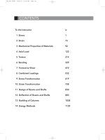
To the Instructor iv
1 Stress 1
2 Strain 73
3 Mechanical Properties of Materials 92
4 Axial Load 122
5 Torsion 214
6 Bending 329
7 Transverse Shear 472
8 Combined Loadings 532
9 Stress Transformation 619
10 Strain Transformation 738
11 Design of Beams and Shafts 830
12 Deflection of Beams and Shafts 883
13 Buckling of Columns 1038
14 Energy Methods 1159
CONTENTS
FM_TOC 46060 6/22/10 11:26 AM Page iii
1
(a)
Ans.
(b)
Ans. F
A
= 34.9 kN
+
c
©F
y
= 0;
F
A
- 4.5 - 4.5 - 5.89 - 6 - 6 - 8 = 0
F
A
= 13.8 kip
+
c
©F
y
= 0;
F
A
- 1.0 - 3 - 3 - 1.8 - 5 = 0
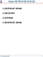
1–1. Determine the resultant internal normal force acting
on the cross section through point A in each column. In
(a), segment BC weighs 180
>
ft and segment CD weighs
250
>
ft. In (b), the column has a mass of 200 >m.kglb
lb
© 2010 Pearson Education, Inc., Upper Saddle River, NJ. All rights reserved. This material is protected under all copyright laws as they currently
exist. No portion of this material may be reproduced, in any form or by any means, without permission in writing from the publisher.
8 kN
3 m
1 m
6 kN6 kN
4.5 kN4.5 kN
200 mm200 mm
A
(b)
200 mm200 mm
3 kip3 kip
5 kip
10 ft
4 ft
4 ft
8 in.8 in.
A
C
D
(a)
B
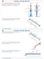
1–2. Determine the resultant internal torque acting on the
cross sections through points C and D.The support bearings
at A and B allow free turning of the shaft.
Ans.
Ans.©M
x
= 0;
T
D
= 0
T
C
= 250 N
#
m
©M
x
= 0;
T
C
- 250 = 0
A
B
D
C
300 mm
200 mm
150 mm
200 mm
250 mm
150 mm
400 Nиm
150 Nиm
250 Nиm
Ans.
Ans. T
C
= 500 lb
#
ft
©M
x
= 0;
T
C
- 500 = 0
T
B
= 150 lb
#
ft
©M
x
= 0;
T
B
+ 350 - 500 = 0
1–3. Determine the resultant internal torque acting on the
cross sections through points B and C.
3 ft
2 ft
2 ft
1 ft
B
A
C
500 lbиft
350 lbиft
600 lbиft
01 Solutions 46060 5/6/10 2:43 PM Page 1
2
© 2010 Pearson Education, Inc., Upper Saddle River, NJ. All rights reserved. This material is protected under all copyright laws as they currently
exist. No portion of this material may be reproduced, in any form or by any means, without permission in writing from the publisher.
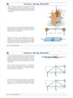
*1–4. A force of 80 N is supported by the bracket as
shown. Determine the resultant internal loadings acting on
the section through point A.
Equations of Equilibrium:
Ans.
Ans.
a
Ans.
or
a
Ans.
Negative sign indicates that M
A
acts in the opposite direction to that shown on FBD.
M
A
=-0.555 N
#
m
-80 cos 15°(0.1 cos 30°) = 0
+
©M
A
= 0;
M
A
+ 80 sin 15°(0.3 + 0.1 sin 30°)
M
A
=-0.555 N
#
m
-
80 sin 45°(0.1 + 0.3 sin 30°) = 0
+
©M
A
= 0;
M
A
+ 80 cos 45°(0.3 cos 30°)
V
A
= 20.7 N
a
+
©F
y¿
= 0;
V
A
- 80 sin 15° = 0
N
A
= 77.3 N
+
Q©F
x¿
= 0;
N
A
- 80 cos 15° = 0
0.1 m
0.3 m
30Њ
80 N
A
45Њ
01 Solutions 46060 5/6/10 2:43 PM Page 2
3
Support Reactions: For member AB
a
Equations of Equilibrium: For point D
Ans.
Ans.
a
Ans.
Equations of Equilibrium: For point E
Ans.
Ans.
a
Ans.
Negative signs indicate that M
E
and V
E
act in the opposite direction to that shown
on FBD.
M
E
=-24.0 kip
#
ft
+©M
E
= 0;
M
E
+ 6.00(4) = 0
V
E
=-9.00 kip
+
c
©F
y
= 0;
-6.00 - 3 - V
E
= 0
:
+
©F
x
= 0;
N
E
= 0
M
D
= 13.5 kip
#
ft
+©M
D
= 0;
M
D
+ 2.25(2) - 3.00(6) = 0
V
D
= 0.750 kip
+
c
©F
y
= 0;
3.00 - 2.25 - V
D
= 0
:
+
©F
x
= 0;
N
D
= 0
+
c
©F
y
= 0;
B
y
+ 3.00 - 9.00 = 0
B
y
= 6.00 kip
:
+
©F
x
= 0;
B
x
= 0
+ ©M
B
= 0;
9.00(4) - A
y
(12) = 0
A
y
= 3.00 kip
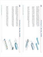
•1–5. Determine the resultant internal loadings in the
beam at cross sections through points D and E. Point E is
just to the right of the 3-kip load.
© 2010 Pearson Education, Inc., Upper Saddle River, NJ. All rights reserved. This material is protected under all copyright laws as they currently
exist. No portion of this material may be reproduced, in any form or by any means, without permission in writing from the publisher.
6 ft
4 ft
A
4 ft
B
C
DE
6 ft
3 kip
1.5 kip/
ft
01 Solutions 46060 5/6/10 2:43 PM Page 3
4
Support Reactions:
a
Equations of Equilibrium: For point C
Ans.
Ans.
a
Ans.
Negative signs indicate that N
C
and V
C
act in the opposite direction to that shown
on FBD.
M
C
= 6.00 kN
#
m
+©M
C
= 0;
8.00(0.75) - M
C
= 0
V
C
=-8.00 kN
+
c
©F
y
= 0;
V
C
+ 8.00 = 0
N
C
=-30.0 kN
:
+
©F
x
= 0;
-N
C
- 30.0 = 0
+
c
©F
y
= 0;
A
y
- 8 = 0
A
y
= 8.00 kN
:
+
©F
x
= 0;
30.0 - A
x
= 0
A
x
= 30.0 kN
+©M
A
= 0;
8(2.25) - T(0.6) = 0
T = 30.0 kN
1–6. Determine the normal force, shear force, and moment
at a section through point C.Take P = 8
kN.
© 2010 Pearson Education, Inc., Upper Saddle River, NJ. All rights reserved. This material is protected under all copyright laws as they currently
exist. No portion of this material may be reproduced, in any form or by any means, without permission in writing from the publisher.
0.75 m
C
P
A
B
0.5 m
0.1 m
0.75 m 0.75 m
Support Reactions:
a
Ans.
Equations of Equilibrium: For point C
Ans.
Ans.
a
Ans.
Negative signs indicate that N
C
and V
C
act in the opposite direction to that shown
on FBD.
M
C
= 0.400 kN
#
m
+©M
C
= 0;
0.5333(0.75) - M
C
= 0
V
C
=-0.533 kN
+
c
©F
y
= 0;
V
C
+ 0.5333 = 0
N
C
=-2.00 kN
:
+
©F
x
= 0;
-N
C
- 2.00 = 0
+
c
©F
y
= 0;
A
y
- 0.5333 = 0
A
y
= 0.5333 kN
:
+
©F
x
= 0;
2 - A
x
= 0
A
x
= 2.00 kN
P = 0.5333 kN = 0.533 kN
+©M
A
= 0;
P(2.25) - 2(0.6) = 0
1–7. The cable will fail when subjected to a tension of 2 kN.
Determine the largest vertical load P the frame will support
and calculate the internal normal force, shear force, and
moment at the cross section through point C for this loading.
0.75 m
C
P
A
B
0.5 m
0.1 m
0.75 m 0.75 m
01 Solutions 46060 5/6/10 2:43 PM Page 4
5
© 2010 Pearson Education, Inc., Upper Saddle River, NJ. All rights reserved. This material is protected under all copyright laws as they currently
exist. No portion of this material may be reproduced, in any form or by any means, without permission in writing from the publisher.
Referring to the FBD of the entire beam, Fig. a,
a
Referring to the FBD of this segment, Fig. b,
Ans.
Ans.
a Ans.+©M
C
= 0;
M
C
+ 6(0.5) - 7.5(1) = 0
M
C
= 4.50 kN
#
m
+
c
©F
y
= 0;
7.50 - 6 - V
C
= 0
V
C
= 1.50 kN
:
+
©F
x
= 0;
N
C
= 0
+©M
B
= 0;
-A
y
(4) + 6(3.5) +
1
2
(3)(3)(2) = 0
A
y
= 7.50 kN
*1–8. Determine the resultant internal loadings on the
cross section through point C. Assume the reactions at
the supports A and B are vertical.
0.5 m
0.5 m
1.5 m1.5 m
C
A
B
3 kN/m
6 kN
D
Referring to the FBD of the entire beam, Fig. a,
a
Referring to the FBD of this segment, Fig. b,
Ans.
Ans.
a
Ans. = 3.94 kN
#
m
+©M
D
= 0;
3.00(1.5) -
1
2
(1.5)(1.5)(0.5) - M
D
= 0
M
D
= 3.9375 kN
#
m
+
c
©F
y
= 0;
V
D
-
1
2
(1.5)(1.5) + 3.00 = 0
V
D
=-1.875 kN
:
+
©F
x
= 0;
N
D
= 0
+©M
A
= 0;
B
y
(4) - 6(0.5) -
1
2
(3)(3)(2) = 0
B
y
= 3.00 kN
•1–9. Determine the resultant internal loadings on the
cross section through point D. Assume the reactions at
the supports A and B are vertical.
0.5 m
0.5 m
1.5 m1.5 m
C
A
B
3 kN/m
6 kN
D
01 Solutions 46060 5/6/10 2:43 PM Page 5
6
© 2010 Pearson Education, Inc., Upper Saddle River, NJ. All rights reserved. This material is protected under all copyright laws as they currently
exist. No portion of this material may be reproduced, in any form or by any means, without permission in writing from the publisher.
Equations of Equilibrium: For point A
Ans.
Ans.
a
Ans.
Negative sign indicates that M
A
acts in the opposite direction to that shown on FBD.
Equations of Equilibrium: For point B
Ans.
Ans.
a
Ans.
Negative sign indicates that M
B
acts in the opposite direction to that shown on FBD.
Equations of Equilibrium: For point C
Ans.
Ans.
a
Ans.
Negative signs indicate that N
C
and M
C
act in the opposite direction to that shown
on FBD.
M
C
=-8125 lb
#
ft =-8.125 kip
#
ft
+©M
C
= 0;
-M
C
- 650(6.5) - 300(13) = 0
N
C
=-1200 lb =-1.20 kip
+
c
© F
y
= 0;
-N
C
- 250 - 650 - 300 = 0
;
+
© F
x
= 0;
V
C
= 0
M
B
=-6325 lb
#
ft =-6.325 kip
#
ft
+© M
B
= 0;
-M
B
- 550(5.5) - 300(11) = 0
V
B
= 850 lb
+
c
© F
y
= 0;
V
B
- 550 - 300 = 0
;
+
© F
x
= 0;
N
B
= 0
M
A
=-1125 lb
#
ft =-1.125 kip
#
ft
+©M
A
= 0;
-M
A
- 150(1.5) - 300(3) = 0
V
A
= 450 lb
+
c
© F
y
= 0;
V
A
- 150 - 300 = 0
;
+
© F
x
= 0;
N
A
= 0
1–10. The boom DF of the jib crane and the column DE
have a uniform weight of 50 lb/ft. If the hoist and load weigh
300 lb, determine the resultant internal loadings in the crane
on cross sections through points A, B, and C.
5 ft
7 ft
C
D
F
E
B
A
300 lb
2 ft 8 ft 3 ft
01 Solutions 46060 5/6/10 2:43 PM Page 6
7
© 2010 Pearson Education, Inc., Upper Saddle River, NJ. All rights reserved. This material is protected under all copyright laws as they currently
exist. No portion of this material may be reproduced, in any form or by any means, without permission in writing from the publisher.
Equations of Equilibrium: For section a–a
Ans.
Ans.
a
Ans. M
A
= 14.5 lb
#
in.
+©M
A
= 0;
-M
A
- 80 sin 15°(0.16) + 80 cos 15°(0.23) = 0
N
A
= 20.7 lb
a
+
©F
y¿
= 0;
N
A
- 80 sin 15° = 0
V
A
= 77.3 lb
+
Q©F
x¿
= 0;
V
A
- 80 cos 15° = 0
1–11. The force acts on the gear tooth.
Determine the resultant internal loadings on the root of the
tooth, i.e., at the centroid point A of section a–a.
F = 80
lb
a
30Њ
a
F ϭ 80 lb
0.23 in.
45Њ
A
0.16 in.
Support Reactions:
Equations of Equilibrium: For point D
Ans.
Ans.
Ans.
Equations of Equilibrium: For point E
Ans.
Ans.
Ans. M
E
= 18.0 kN
#
m
d+© M
E
= 0;
90.0(0.2) - M
E
= 0
+
c
© F
y
= 0;
N
E
= 0
V
E
= 90.0 kN
:
+
© F
x
= 0;
90.0 - V
E
= 0
M
D
= 21.6 kN
#
m
d+© M
D
= 0;
M
D
+ 18(0.3) - 90.0(0.3) = 0
N
D
= 18.0 kN
+
c
© F
y
= 0;
N
D
- 18 = 0
V
D
= 90.0 kN
:
+
© F
x
= 0;
V
D
- 90.0 = 0
:
+
©F
x
= 0;
N
C
- 90.0 = 0
N
C
= 90.0 kN
N
A
= 90.0 kN
d+©M
C
= 0;
18(0.7) - 18.0(0.2) - N
A
(0.1) = 0
+
c
©F
y
= 0;
N
B
- 18 = 0
N
B
= 18.0 kN
*1–12. The sky hook is used to support the cable of a
scaffold over the side of a building. If it consists of a smooth
rod that contacts the parapet of a wall at points A, B, and C,
determine the normal force, shear force, and moment on
the cross section at points D and E.
0.2 m
0.2 m 0.2 m
0.2 m
0.2 m
0.3 m
0.3 m
18 kN
A
DE
B
C
01 Solutions 46060 5/6/10 2:43 PM Page 7
8
© 2010 Pearson Education, Inc., Upper Saddle River, NJ. All rights reserved. This material is protected under all copyright laws as they currently
exist. No portion of this material may be reproduced, in any form or by any means, without permission in writing from the publisher.
•
1–13. The 800-lb load is being hoisted at a constant speed
using the motor M, which has a weight of 90 lb. Determine
the resultant internal loadings acting on the cross section
through point B in the beam. The beam has a weight of
40 lb
>
ft and is fixed to the wall at A.
M
4 ft
3 ft 4 ft
CB
1.5 ft
A
0.25 ft
4 ft 3 ft
D
1–14. Determine the resultant internal loadings acting on
the cross section through points C and D of the beam in
Prob. 1–13.
M
4 ft
3 ft 4 ft
CB
1.5 ft
A
0.25 ft
4 ft 3 ft
D
Ans.
Ans.
a
Ans. M
B
=-3.12 kip
#
ft
+ ©M
B
= 0;
- M
B
- 0.16(2) - 0.8(4.25) + 0.4(1.5) = 0
V
B
= 0.960 kip
+
c
©F
y
= 0;
V
B
- 0.8 - 0.16 = 0
N
B
=-0.4 kip
:
+
©F
x
= 0;
- N
B
- 0.4 = 0
For point C:
Ans.
Ans.
a
Ans.
For point D:
Ans.
Ans.
a
Ans. M
D
=-15.7 kip
#
ft
+©M
D
= 0;
- M
D
- 0.09(4) - 0.04(14)(7) - 0.8(14.25) = 0
+
c
©F
y
= 0;
V
D
- 0.09 - 0.04(14) - 0.8 = 0;
V
D
= 1.45 kip
;
+
©F
x
= 0;
N
D
= 0
M
C
=-6.18 kip
#
ft
+ ©M
C
= 0;
- M
C
- 0.8(7.25) - 0.04(7)(3.5) + 0.4(1.5) = 0
+
c
©F
y
= 0;
V
C
- 0.8 - 0.04 (7) = 0;
V
C
= 1.08 kip
;
+
©F
x
= 0;
N
C
+ 0.4 = 0;
N
C
=-0.4kip
01 Solutions 46060 5/6/10 2:43 PM Page 8
© 2010 Pearson Education, Inc., Upper Saddle River, NJ. All rights reserved.This material is protected under all copyright laws as they currently
exist. No portion of this material may be reproduced, in any form or by any means, without permission in writing from the publisher.
1–15. Determine the resultant internal loading on the
cross section through point C of the pliers. There is a pin at
A, and the jaws at B are smooth.
120 mm
40 mm
15 mm
80 mm
A
C
D
30Њ
20 N
20 N
B
9
*1–16. Determine the resultant internal loading on the
cross section through point D of the pliers.
120 mm
40 mm
15 mm
80 mm
A
C
D
30Њ
20 N
20 N
B
Ans.
Ans.
+d Ans.©M
C
= 0;
-M
C
+ 60(0.015) = 0;
M
C
= 0.9 N.m
:
+
©F
x
= 0;
N
C
= 0
+
c
©F
y
= 0;
-V
C
+ 60 = 0;
V
C
= 60
N
Ans.
Ans.
+d Ans.©M
D
= 0;
M
D
- 20(0.08) = 0;
M
D
= 1.60 N.m
+b©F
x
= 0;
N
D
- 20 sin 30° = 0;
N
D
= 10 N
R+©F
y
= 0;
V
D
- 20 cos 30° = 0;
V
D
= 17.3 N
01 Solutions 46060 5/6/10 2:43 PM Page 9
10
© 2010 Pearson Education, Inc., Upper Saddle River, NJ. All rights reserved.This material is protected under all copyright laws as they currently
exist. No portion of this material may be reproduced, in any form or by any means, without permission in writing from the publisher.
45Њ
1.5 m
1.5 m
3 m
45Њ
A
C
B
b
a
a
b
5 kN
Referring to the FBD of the entire beam, Fig. a,
a
Referring to the FBD of this segment (section a–a), Fig. b,
Ans.
Ans.
a Ans.
Referring to the FBD (section b–b) in Fig. c,
Ans.
Ans.
a
Ans.M
b-b
= 3.75 kN
#
m
+©M
C
= 0;
5.303 sin 45° (3) - 5(1.5) - M
b-b
= 0
+
c
©F
y
= 0;
V
b-b
- 5 sin 45° = 0
V
b-b
= 3.536 kN = 3.54 kN
=-1.77 kN
;
+
©F
x
= 0;
N
b-b
- 5 cos 45° + 5.303 = 0
N
b-b
=-1.768 kN
+ ©M
C
= 0;
5.303 sin 45°(3) - 5(1.5) - M
a-a
= 0
M
a-a
= 3.75 kN
#
m
+a ©F
y¿
= 0;
V
a-a
+ 5.303 sin 45° - 5 = 0
V
a-a
= 1.25 kN
+b©F
x¿
= 0;
N
a-a
+ 5.303 cos 45° = 0
N
a-a
=-3.75 kN
+ ©M
A
= 0;
N
B
sin 45°(6) - 5(4.5) = 0
N
B
= 5.303 kN
•1–17. Determine resultant internal loadings acting on
section a–a and section b–b. Each section passes through
the centerline at point C.
01 Solutions 46060 5/6/10 2:43 PM Page 10
11
© 2010 Pearson Education, Inc., Upper Saddle River, NJ. All rights reserved.This material is protected under all copyright laws as they currently
exist. No portion of this material may be reproduced, in any form or by any means, without permission in writing from the publisher.
Segment AC:
Ans.
Ans.
a Ans.+©M
C
= 0;
M
C
+ 80(6) = 0;
M
C
=-480 lb
#
in.
+
c
©F
y
= 0;
V
C
= 0
:
+
©F
x
= 0;
N
C
+ 80 = 0;
N
C
=-80 lb
1–18. The bolt shank is subjected to a tension of 80 lb.
Determine the resultant internal loadings acting on the
cross section at point C.
AB
C
90Њ
6 in.
Referring to the FBD of the entire beam, Fig. a,
a
Referring to the FBD of this segment, Fig. b,
Ans.
Ans.
a
Ans. M
C
= 31.5 kip
#
ft
+©M
C
= 0;
M
C
+ (3)(3)(1.5) +
1
2
(3)(3)(2) - 18.0(3) = 0
+
c
©F
y
= 0;
18.0 -
1
2
(3)(3) - (3)(3) - V
C
= 0
V
C
= 4.50 kip
:
+
©F
x
= 0;
N
C
= 0
+ ©M
B
= 0;
1
2
(6)(6)(2) +
1
2
(6)(6)(10) - A
y
(12) = 0
A
y
= 18.0 kip
1–19. Determine the resultant internal loadings acting on
the cross section through point C. Assume the reactions at
the supports A and B are vertical.
3 ft 3 ft
D
C
AB
6 ft
6 kip/ft
6 kip/ft
01 Solutions 46060 5/6/10 2:43 PM Page 11
12
© 2010 Pearson Education, Inc., Upper Saddle River, NJ. All rights reserved.This material is protected under all copyright laws as they currently
exist. No portion of this material may be reproduced, in any form or by any means, without permission in writing from the publisher.
Referring to the FBD of the entire beam, Fig. a,
a
Referring to the FBD of this segment, Fig. b,
Ans.
Ans.
a Ans.+©M
A
= 0;
M
D
- 18.0 (2) = 0
M
D
= 36.0 kip
#
ft
+
c
©F
y
= 0;
18.0 -
1
2
(6)(6) - V
D
= 0
V
D
= 0
:
+
©F
x
= 0;
N
D
= 0
+©M
B
= 0;
1
2
(6)(6)(2) +
1
2
(6)(6)(10) - A
y
(12) = 0
A
y
= 18.0 kip
*1–20. Determine the resultant internal loadings acting
on the cross section through point D. Assume the reactions
at the supports A and B are vertical.
3 ft 3 ft
D
C
AB
6 ft
6 kip/ft
6 kip/ft
Internal Loadings: Referring to the free-body diagram of the section of the clamp
shown in Fig. a,
Ans.
Ans.
a Ans.+©M
A
= 0;
900(0.2) - M
a-a
= 0
M
a-a
= 180 N
#
m
©F
x¿
= 0;
V
a-a
- 900 sin 30° = 0
V
a-a
= 450 N
©F
y¿
= 0;
900 cos 30° - N
a-a
= 0
N
a-a
= 779 N
•1–21. The forged steel clamp exerts a force of N
on the wooden block. Determine the resultant internal
loadings acting on section a–a passing through point A.
F = 900
200 mm
a
a
F ϭ 900 N
F ϭ 900 N
30Њ
A
01 Solutions 46060 5/6/10 2:43 PM Page 12
13
© 2010 Pearson Education, Inc., Upper Saddle River, NJ. All rights reserved.This material is protected under all copyright laws as they currently
exist. No portion of this material may be reproduced, in any form or by any means, without permission in writing from the publisher.
Support Reactions: We will only need to compute F
EF
by writing the moment
equation of equilibrium about D with reference to the free-body diagram of the
hook, Fig. a.
a
Internal Loadings: Using the result for F
EF
, section FG of member EF will be
considered. Referring to the free-body diagram, Fig. b,
Ans.
Ans.
a Ans.+©M
G
= 0;
M
G
= 0
+
c
©F
y
= 0;
V
G
= 0
:
+
©F
x
= 0;
9810 - N
G
= 0
N
G
= 9810 N = 9.81 kN
+©M
D
= 0;
F
EF
(0.3) - 600(9.81)(0.5) = 0
F
EF
= 9810 N
1–22. The floor crane is used to lift a 600-kg concrete pipe.
Determine the resultant internal loadings acting on the
cross section at G.
0.2 m
0.2 m
0.4 m
0.3 m
0.5 m
75Њ
0.6 m
C
A
E
B
F
D
H
G
01 Solutions 46060 5/6/10 2:43 PM Page 13
14
© 2010 Pearson Education, Inc., Upper Saddle River, NJ. All rights reserved.This material is protected under all copyright laws as they currently
exist. No portion of this material may be reproduced, in any form or by any means, without permission in writing from the publisher.
Support Reactions: Referring to the free-body diagram of the hook, Fig. a.
a
Subsequently, referring to the free-body diagram of member BCD,Fig.b,
a
Internal Loadings: Using the results of B
x
and B
y
, section BH of member BCD will
be considered. Referring to the free-body diagram of this part shown in Fig. c,
Ans.
Ans.
a
Ans.
The negative signs indicates that N
H
, V
H
, and M
H
act in the opposite sense to that
shown on the free-body diagram.
=-4.12 kN
#
m
+©M
D
= 0;
M
H
+ 20601(0.2) = 0
M
H
=-4120.2 N
#
m
+
c
©F
y
= 0;
-V
H
- 2060 = 0
V
H
=-20601 N =-20.6 kN
:
+
©F
x
= 0;
N
H
+ 2712.83 = 0
N
H
=-2712.83 N =-2.71 kN
+
c
©F
y
= 0;
27 421.36 sin 75° - 5886 - B
y
= 0
B
y
= 20 601 N
:
+
©F
x
= 0;
B
x
+ 27 421.36 cos 75° - 9810 = 0
B
x
= 2712.83 N
+©M
B
= 0;
F
AC
sin 75°(0.4) - 5886(1.8) = 0
F
AC
= 27 421.36 N
+
c
©F
y
= 0;
D
y
- 600(9.81) = 0
D
y
= 5886 N
+©M
F
= 0;
D
x
(0.3) - 600(9.81)(0.5) = 0
D
x
= 9810 N
1–23. The floor crane is used to lift a 600-kg concrete pipe.
Determine the resultant internal loadings acting on the
cross section at H.
0.2 m
0.2 m
0.4 m
0.3 m
0.5 m
75Њ
0.6 m
C
A
E
B
F
D
H
G
01 Solutions 46060 5/6/10 2:43 PM Page 14
15
© 2010 Pearson Education, Inc., Upper Saddle River, NJ. All rights reserved.This material is protected under all copyright laws as they currently
exist. No portion of this material may be reproduced, in any form or by any means, without permission in writing from the publisher.
Support Reactions: We will only need to compute N
A
by writing the moment
equation of equilibrium about B with reference to the free-body diagram of the
steamroller, Fig. a.
a
Internal Loadings: Using the result for N
A
, the free-body diagram of the front roller
shown in Fig. b will be considered.
Ans.
Ans.
a
Ans.= 4.46 kN
#
m
+©M
C
= 0;
53.51(10
3
)(2) - 5(10
3
)(9.81)(2) - 2M
C
= 0
M
C
= 4459.10 N
#
m
=-2.23 kN
+
c
©F
y
= 0;
2V
C
+ 53.51(10
3
) - 5(10
3
)(9.81) = 0
V
C
=-2229.55 N
;
+
©F
x
= 0;
2N
C
= 0
N
C
= 0
+©M
B
= 0;
N
A
(5.5) - 20(10
3
)(9.81)(1.5) = 0
N
A
= 53.51(10
3
) N
*1–24. The machine is moving with a constant velocity. It
has a total mass of 20 Mg, and its center of mass is located at
G, excluding the front roller. If the front roller has a mass of
5 Mg, determine the resultant internal loadings acting on
point C of each of the two side members that support the
roller. Neglect the mass of the side members. The front
roller is free to roll.
4 m
2 m
1.5 m
A
C
B
G
01 Solutions 46060 5/6/10 2:43 PM Page 15
16
© 2010 Pearson Education, Inc., Upper Saddle River, NJ. All rights reserved.This material is protected under all copyright laws as they currently
exist. No portion of this material may be reproduced, in any form or by any means, without permission in writing from the publisher.
Ans.
Ans.
Ans.
Ans.
Ans.
Ans.©M
z
= 0;
(T
B
)
z
- 105(0.5) = 0;
(T
B
)
z
= 52.5 lb
#
ft
©M
y
= 0;
(M
B
)
y
- 105(7.5) = 0;
(M
B
)
y
= 788 lb
#
ft
©M
x
= 0;
(M
B
)
x
= 0
©F
z
= 0;
(N
B
)
z
= 0
©F
y
= 0;
(V
B
)
y
= 0
©F
x
= 0;
(V
B
)
x
- 105 = 0;
(V
B
)
x
= 105 lb
•1–25. Determine the resultant internal loadings acting on
the cross section through point B of the signpost.The post is
fixed to the ground and a uniform pressure of 7
>
acts
perpendicular to the face of the sign.
ft
2
lb
4 ft
z
y
6 ft
x
B
A
3 ft
2 ft
3 ft
7 lb/ft
2
1–26. The shaft is supported at its ends by two bearings A
and B and is subjected to the forces applied to the pulleys
fixed to the shaft. Determine the resultant internal
loadings acting on the cross section located at point C.The
300-N forces act in the Ϫz direction and the 500-N forces
act in the ϩx direction. The journal bearings at A and B
exert only x and z components of force on the shaft.
y
B
C
400 mm
150 mm
200 mm
250 mm
A
x
z
300 N
300 N
500 N
500 N
Ans.
Ans.
Ans.
Ans.
Ans.
Ans.©M
z
= 0;
(M
C
)
z
- 1000(0.2) + 750(0.45) = 0;
(M
C
)
z
=-138 N
#
m
©M
y
= 0;
(T
C
)
y
= 0
©M
x
= 0;
(M
C
)
x
+ 240(0.45) = 0;
(M
C
)
x
=-108 N
#
m
©F
z
= 0;
(V
C
)
z
+ 240 = 0;
(V
C
)
z
=-240 N
©F
y
= 0;
(N
C
)
y
= 0
©F
x
= 0;
(V
C
)
x
+ 1000 - 750 = 0;
(V
C
)
x
=-250 N
01 Solutions 46060 5/6/10 2:43 PM Page 16
17
© 2010 Pearson Education, Inc., Upper Saddle River, NJ. All rights reserved.This material is protected under all copyright laws as they currently
exist. No portion of this material may be reproduced, in any form or by any means, without permission in writing from the publisher.
Ans.
Ans.
Ans.
Ans.
Ans.
Ans.©M
z
= 0;
(M
B
)
z
= 0
(M
B
)
y
= 6.23 N
#
m
©M
y
= 0;
(M
B
)
y
+ (0.2)(12)(9.81)(0.1) + (0.4)(12)(9.81)(0.2) - 60(0.3) = 0
(T
B
)
x
= 9.42 N
#
m
©M
x
= 0;
(T
B
)
x
+ 60(0.4) - 60(0.4) - (0.4)(12)(9.81)(0.2) = 0
(V
B
)
z
= 70.6 N
©F
z
= 0;
(V
B
)
z
- 60 + 60 - (0.2)(12)(9.81) - (0.4)(12)(9.81) = 0
©F
y
= 0;
(V
B
)
y
= 0
©F
x
= 0;
(N
B
)
x
= 0
1–27. The pipe has a mass of 12
>
m. If it is fixed to the
wall at A, determine the resultant internal loadings acting on
the cross section at B. Neglect the weight of the wrench CD.
kg
300 mm
200 mm
150 mm
60 N
60 N
400 mm
150 mm
B
A
x
y
z
C
D
01 Solutions 46060 5/6/10 2:43 PM Page 17
18
© 2010 Pearson Education, Inc., Upper Saddle River, NJ. All rights reserved.This material is protected under all copyright laws as they currently
exist. No portion of this material may be reproduced, in any form or by any means, without permission in writing from the publisher.
Internal Loading: Referring to the free-body diagram of the section of the drill and
brace shown in Fig. a,
Ans.
Ans.
Ans.
Ans.
Ans.
Ans.
The negative sign indicates that (M
A
)
Z
acts in the opposite sense to that shown on
the free-body diagram.
©M
z
= 0;
A
M
A
B
z
+ 30(1.25) = 0
A
M
A
B
z
=-37.5 lb
#
ft
©M
y
= 0;
A
T
A
B
y
- 30(0.75) = 0
A
T
A
B
y
= 22.5 lb
#
ft
©M
x
= 0;
A
M
A
B
x
- 10(2.25) = 0
A
M
A
B
x
= 22.5 lb
#
ft
©F
z
= 0;
A
V
A
B
z
- 10 = 0
A
V
A
B
z
= 10 lb
©F
y
= 0;
A
N
A
B
y
- 50 = 0
A
N
A
B
y
= 50 lb
©F
x
= 0;
A
V
A
B
x
- 30 = 0
A
V
A
B
x
= 30 lb
*1–28. The brace and drill bit is used to drill a hole at O.If
the drill bit jams when the brace is subjected to the forces
shown, determine the resultant internal loadings acting on
the cross section of the drill bit at A.
z
x
y
A
O
9 in.
6 in.
6 in.
6 in.
9 in.
3 in.
F
x
ϭ 30 lb
F
y
ϭ 50 lb
F
z
ϭ 10 lb
01 Solutions 46060 5/6/10 2:43 PM Page 18
19
© 2010 Pearson Education, Inc., Upper Saddle River, NJ. All rights reserved.This material is protected under all copyright laws as they currently
exist. No portion of this material may be reproduced, in any form or by any means, without permission in writing from the publisher.
Equations of Equilibrium: For point A
Ans.
Ans.
Ans. M
A
= Pr(1 - cos u)
d+©M
A
= 0;
M
A
- P[r(1 - cos u)] = 0
V
A
= P sin u
Q+©F
y
= 0;
V
A
- P sin u = 0
N
A
= P cos u
R+©F
x
= 0;
P cos u - N
A
= 0
•1–29. The curved rod has a radius r and is fixed to the
wall at B. Determine the resultant internal loadings acting
on the cross section through A which is located at an angle u
from the horizontal.
r
A
B
P
U
01 Solutions 46060 5/6/10 2:43 PM Page 19
20
© 2010 Pearson Education, Inc., Upper Saddle River, NJ. All rights reserved.This material is protected under all copyright laws as they currently
exist. No portion of this material may be reproduced, in any form or by any means, without permission in writing from the publisher.
(1)
(2)
(3)
(4)
Since is can add, then ,
Eq. (1) becomes
Neglecting the second order term,
QED
Eq. (2) becomes
Neglecting the second order term,
QED
Eq. (3) becomes
Neglecting the second order term,
QED
Eq. (4) becomes
Neglecting the second order term,
QED
dM
du
=-T
Tdu + dM = 0
Tdu + dM +
dTdu
2
= 0
dT
du
= M
Mdu - dT = 0
Mdu - dT +
dMdu
2
= 0
dV
du
=-N
Ndu + dV = 0
Ndu + dV +
dNdu
2
= 0
dN
du
= V
Vdu - dN = 0
Vdu - dN +
dVdu
2
= 0
cos
du
2
= 1sin
du
2
=
du
2
du
2
T sin
du
2
- M cos
du
2
+ (T + dT) sin
du
2
+ (M + dM) cos
du
2
= 0
©M
y
= 0;
T cos
du
2
+ M sin
du
2
- (T + dT) cos
du
2
+ (M + dM) sin
du
2
= 0
©M
x
= 0;
N sin
du
2
- V cos
du
2
+ (N + dN) sin
du
2
+ (V + dV) cos
du
2
= 0
©F
y
= 0;
N cos
du
2
+ V sin
du
2
- (N + dN) cos
du
2
+ (V + dV) sin
du
2
= 0
©F
x
= 0;
1–30. A differential element taken from a curved bar is
shown in the figure. Show that
and dT>du = M.dM>du =-T,
dV>du =-N,dN>du = V,
M
V
N
d
u
M ϩ dM
T ϩ d
T
N ϩ dN
V ϩ dV
T
01 Solutions 46060 5/6/10 2:43 PM Page 20
21
© 2010 Pearson Education, Inc., Upper Saddle River, NJ. All rights reserved.This material is protected under all copyright laws as they currently
exist. No portion of this material may be reproduced, in any form or by any means, without permission in writing from the publisher.
Ans.s =
P
A
=
8 (10
3
)
4.4 (10
-3
)
= 1.82 MPa
= 4400 mm
2
= 4.4 (10
-3
) m
2
A = (2)(150)(10) + (140)(10)
1–31. The column is subjected to an axial force of 8 kN,
which is applied through the centroid of the cross-sectional
area. Determine the average normal stress acting at section
a–a. Show this distribution of stress acting over the area’s
cross section.
8 kN
a
a
75 mm
10 mm
10 mm
10 mm
75 mm
70 mm
70 mm
a
Ans.t
avg
=
V
A
=
833.33
p
4
(
6
1000
)
2
= 29.5 MPa
+©M
O
= 0;
-F(12) + 20(500) = 0;
F = 833.33 N
*1–32. The lever is held to the fixed shaft using a tapered
pin AB, which has a mean diameter of 6 mm. If a couple is
applied to the lever, determine the average shear stress in
the pin between the pin and lever.
20 N
20 N
250 mm
250 mm
12 mm
A
B
01 Solutions 46060 5/6/10 2:43 PM Page 21
22
© 2010 Pearson Education, Inc., Upper Saddle River, NJ. All rights reserved.This material is protected under all copyright laws as they currently
exist. No portion of this material may be reproduced, in any form or by any means, without permission in writing from the publisher.
Equations of Equilibrium:
Average Normal Stress and Shear Stress: Area at plane, .
Ans.
Ans. =
P
A
sin u cos u =
P
2A
sin 2u
t
avg
=
V
A¿
=
P cos u
A
sin u
s =
N
A¿
=
P sin u
A
sin u
=
P
A
sin
2
u
A¿=
A
sin u
u
Q+©F
y
= 0;
N - P sin u = 0
N = P sin u
R+©F
x
= 0;
V - P cos u = 0
V = P cos u
•1–33. The bar has a cross-sectional area A and is
subjected to the axial load P. Determine the average
normal and average shear stresses acting over the shaded
section, which is oriented at from the horizontal. Plot the
variation of these stresses as a function of u 10 … u … 90°2.
u
P
u
P
A
At D:
Ans.
At E:
Ans.s
E
=
P
A
=
8(10
3
)
p
4
(0.012
2
)
= 70.7 MPa (T)
s
D
=
P
A
=
4(10
3
)
p
4
(0.028
2
- 0.02
2
)
= 13.3 MPa
(C)
1–34. The built-up shaft consists of a pipe AB and solid
rod BC.The pipe has an inner diameter of 20 mm and outer
diameter of 28 mm. The rod has a diameter of 12 mm.
Determine the average normal stress at points D and E and
represent the stress on a volume element located at each of
these points.
C
E
D
A
4 kN
8 kN
B
6 kN
6 kN
01 Solutions 46060 5/6/10 2:43 PM Page 22
23
© 2010 Pearson Education, Inc., Upper Saddle River, NJ. All rights reserved.This material is protected under all copyright laws as they currently
exist. No portion of this material may be reproduced, in any form or by any means, without permission in writing from the publisher.
Joint A:
Ans.
Ans.
Joint E:
Ans.
Ans.
Joint B:
Ans.
Ans.s
BD
=
F
BD
A
BD
=
23.33
1.25
= 18.7 ksi
(C)
s
BC
=
F
BC
A
BC
=
29.33
1.25
= 23.5 ksi
(T)
s
EB
=
F
EB
A
EB
=
6.0
1.25
= 4.80 ksi
(T)
s
ED
=
F
ED
A
ED
=
10.67
1.25
= 8.53 ksi
(C)
s
AE
=
F
AE
A
AE
=
10.67
1.25
= 8.53 ksi
(C)
s
AB
=
F
AB
A
AB
=
13.33
1.25
= 10.7 ksi
(T)
1–35. The bars of the truss each have a cross-sectional
area of Determine the average normal stress in
each member due to the loading State whether
the stress is tensile or compressive.
P = 8 kip.
1.25 in
2
.
3 ft
4 ft 4 ft
P
0.75 P
E
D
A
BC
01 Solutions 46060 5/6/10 2:43 PM Page 23
24
© 2010 Pearson Education, Inc., Upper Saddle River, NJ. All rights reserved.This material is protected under all copyright laws as they currently
exist. No portion of this material may be reproduced, in any form or by any means, without permission in writing from the publisher.
Joint A:
Joint E:
Joint B:
The highest stressed member is BC:
Ans.
P = 6.82 kip
s
BC
=
(3.67)P
1.25
= 20
F
BC
= (3.67)P
:
+
©F
x
= 0;
F
BC
- (2.9167)Pa
4
5
b- (1.667)Pa
4
5
b= 0
F
BD
= (2.9167)P
+
c
©F
y
= 0;
a
3
5
bF
BD
- (0.75)P - (1.667)Pa
3
5
b= 0
F
ED
= (1.333)P
:
+
©F
x
= 0;
(1.333)P - F
ED
= 0
F
EB
= (0.75)P
+
c
©F
y
= 0;
F
EB
- (0.75)P = 0
F
AE
= (1.333)P
:
+
©F
x
= 0;
-F
AE
+ (1.667)Pa
4
5
b= 0
F
AB
= (1.667)P
+
c
©F
y
= 0;
-P + a
3
5
bF
AB
= 0
*1–36. The bars of the truss each have a cross-sectional
area of If the maximum average normal stress in
any bar is not to exceed 20 ksi, determine the maximum
magnitude P of the loads that can be applied to the truss.
1.25 in
2
.
3 ft
4 ft 4 ft
P
0.75 P
E
D
A
BC
01 Solutions 46060 5/6/10 2:43 PM Page 24