Chapter 6. Synchronous Machines potx
Bạn đang xem bản rút gọn của tài liệu. Xem và tải ngay bản đầy đủ của tài liệu tại đây (545.23 KB, 31 trang )
48550 Electrical Energy Technology
Chapter 6.
Synchronous Machines
Topics to cover:
1) Introduction
2) Synchronous machine structures
3) Rotating magnetic field
4) Equivalent circuit model
5) Performance as a generator
6) Performance as a motor
Introduction
A synchronous machine is an ac rotating machine whose speed under steady state
condition is proportional to the frequency of the current in its armature. The magnetic field
created by the armature currents rotates at the same speed as that created by the field current
on the rotor, which is rotating at the synchronous speed, and a steady torque results.
Synchronous machines are commonly used as generators especially for large power
systems, such as turbine generators and hydroelectric generators in the grid power supply.
Because the rotor speed is proportional to the frequency of excitation, synchronous motors
can be used in situations where constant speed drive is required. Since the reactive power
generated by a synchronous machine can be adjusted by controlling the magnitude of the
rotor field current, unloaded synchronous machines are also often installed in power systems
solely for power factor correction or for control of reactive kVA flow. Such machines,
known as synchronous condensers, may be more economical in the large sizes than static
capacitors.
With power electronic variable voltage variable frequency (VVVF) power supplies,
synchronous motors, especially those with permanent magnet rotors, are widely used for
variable speed drives. If the stator excitation of a permanent magnet motor is controlled by
its rotor position such that the stator field is always 90
o
(electrical) ahead of the rotor, the
motor performance can be very close to the conventional brushed dc motors, which is very
much favored for variable speed drives. The rotor position can be either detected by using
rotor position sensors or deduced from the induced emf in the stator windings. Since this
type of motors do not need brushes, they are known as brushless dc motors.
Synchronous Machines
2
In this chapter, we concentrate on conventional synchronous machines whereas the
brushless dc motors will be discussed later in a separate chapter.
Synchronous Machine Structures
Stator and Rotor
The armature winding of a conventional synchronous machine is almost invariably on
the stator and is usually a three phase winding. The field winding is usually on the rotor
and excited by dc current, or permanent magnets. The dc power supply required for
excitation usually is supplied through a dc generator known as exciter, which is often
mounted on the same shaft as the synchronous machine. Various excitation systems using
ac exciter and solid state rectifiers are used with large turbine generators.
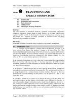
There are two types of rotor structures: round or cylindrical rotor and salient pole rotor
as illustrated schematically in the diagram below. Generally, round rotor structure is used
for high speed synchronous machines, such as steam turbine generators, while salient pole
structure is used for low speed applications, such as hydroelectric generators. The pictures
below show the stator and rotor of a hydroelectric generator and the rotor of a turbine
generator.
(a) (b)
Schematic illustration of synchronous machines of
(a) round or cylindrical rotor and (b) salient rotor structures
Synchronous Machines
3
Synchronous Machines
4
Angle in Electrical and Mechanical Units
Consider a synchronous machine with two magnetic poles. The idealized radial
distribution of the air gap flux density is sinusoidal along the air gap. When the rotor
rotates for one revolution, the induced emf, which is also sinusoidal, varies for one cycle as
illustrated by the waveforms in the diagram below. If we measure the rotor position by
physical or mechanical degrees or radians and the phase angles of the flux density and emf
by electrical degrees or radians, in this case, it is ready to see that the angle measured in
mechanical degrees or radians is equal to that measured in electrical degrees or radians, i.e.
θ θ=
m
where θ is the angle in electrical degrees or radians and θ
m
the mechanical angle.
Synchronous Machines
5
B(θ) e ω )( t&
B(θ)
e ω )( t
ωt
θ &
π/
2
π π/2
3
π20
π π2
θ m
B(θ) e ω )( t&
B(
θ
)
e ω )( t
ωt
θ &
π π2
0
π
π4
3
π2
π
θ
m
(a) (b)
Flux density distribution in air gap and induced emf in the phase
winding of a (a) two pole and (b) four pole synchronous machine
A great many synchronous machines have more than two poles. As a specific example,
we consider a four pole machine. As the rotor rotates for one revolution (θ
m
=2π), the
induced emf varies for two cycles (θ = 4π), and hence
θ θ= 2
m
For a general case, if a machine has P poles, the relationship between the electrical and
mechanical units of an angle can be readily deduced as
θ θ=
P
m
2
Taking derivatives on the both side of the above equation, we obtain
ω ω=
P
m
2
Synchronous Machines
6
where ω is the angular frequency of emf in electrical radians per second and ω
m
the angular
speed of the rotor in mechanical radians per second. When ω and ω
m
are converted into
cycles per second or Hz and revolutions per minute respectively, we have
f
P n
=
2 60
or n
f
P
=
120
where ω=2πf , ω
m
=2πn/60, and n is the rotor speed in rev/min. It can be seen that the
frequency of the induced emf is proportional to the rotor speed.
Distributed Three Phase Windings
The stator of a synchronous machine consists of a laminated electrical steel core and a
three phase winding. Fig.(a) below shows a stator lamination of a synchronous machine
that has a number of uniformly distributed slots. Coils are to be laid in these slots and
connected in such a way that the current in each phase winding would produce a magnetic
field in the air gap around the stator periphery as closely as possible the ideal sinusoidal
distribution. Fig.(b) is a picture of a coil.
(a) (b)
Pictures of (a) stator lamination and (b) coil of a synchronous machine
As illustrated below, these coils are connected to form a three phase winding. Each
phase is able to produce a specified number of magnetic poles (in the diagram below, four
magnetic poles are generated by a phase winding). The windings of the three phase are
arranged uniformly around the stator periphery and are labeled in the sequence that phase a
is 120
o
(electrical) ahead of phase b and 240
o
(electrical) ahead of phase c. It is noted that
in the diagrams above, two coil sides are laid in each slot. This type of winding is known as
Synchronous Machines
7
the double layer winding. In the case that there is only one coil side in each slot, the
winding is known as the single layer winding.
Synchronous Machines
8
Rotating Magnetic Fields
Magnetic Field of a Distributed Phase Winding
The magnetic field distribution of a distributed phase winding can be obtained by adding
the fields generated by all the coils of the winding. The diagram below plots the profiles of
mmf and field strength of a single coil in a uniform air gap. If the permeability of the iron is
assumed to be infinite, by Ampere's law, the mmf across each air gap would be Ni
a
/2, where
N is the number of turns of the coil and i
a
the current in the coil. The mmf distribution
along the air gap is a square wave. Because of the uniform air gap, the spatial distribution
of magnetic field strength is the same as that of mmf.
It can be shown analytically that the fundamental component is the major component
when the square wave mmf is expanded into a Fourier Series, and it can written as
F
Ni
a
a
1
4
2
=
π
θcos
where θ is the angular displacement from the magnetic axis of the coil.
When the field distributions of a number of distributed coils are combined, the resultant
field distribution is close to a sine wave, as shown in the diagram in the next page. The
fundamental component of the resultant mmf can be obtained by adding the fundamental
components of these individual coils, and it can expressed as
Synchronous Machines
9
Synchronous Machines
10
F
k N
P
i
a
p ph
a
1
4
=
π
θcos
where N
ph
is the total number of turns of the phase winding, which is formed by these coils,
k
p
is known as the distribution factor of the winding, which is defined by
k
Fundamental mmf of a distributed winding
Fundamental mmf of a concentrated winding
p
=
and P is the number of poles.
In some windings, short pitched coils (the distance between two sides of coil is smaller
than that between two adjacent magnetic poles) are used to eliminate a certain harmonic,
and the fundamental component of the resultant mmf is then expressed as
F
k N
P
i
a
w ph
a1
4
=
π
θcos
where k
w
= k
d
k
p
is the winding factor, k
d
is known as the pitching factor, which is defined by
k
Fundamental mmf of a short pitch winding
Fundamental mmf of a full pitch winding
d
=
and k
w
N
ph
is known as the effective number of turns of the phase winding.
Let i I t
a m
= cosω , and we have
F
k N
P
I t
F t
a
w ph
m
m
1
4
=
=
π
ω θ
ω θ
cos cos
cos cos
where F
k N
P
I
m
w ph
m
=
4
π
The mmf of a distributed phase winding is a function of both space and time. When plotted
at different time instants as shown below, we can see that it is a pulsating sine wave. We
call this type of mmf as a pulsating mmf.
Because
( ) ( )
cos cos
cos cos
α β
α β α β
=
− + +
2
, the above expression of the mmf
fundamental component can be further written as
( ) ( )
F
F
t
F
t
F F
a
m m
1
2 2
= − + +
= +
+ −
cos cosθ ω θ ω
Synchronous Machines
11
It can be shown that the first term in the above equation stands for a rotating mmf in the +θ
direction and the second a rotating mmf in the −θ direction. That is a pulsating mmf can be
resolved into two rotating mmf's with the same magnitudes and opposite rotating directions,
as shown above. For a machine with uniform air gap, the above analysis is also applicable
to the magnetic field strength and flux density in the air gap.
Synchronous Machines
12
Magnetic Field of Three Phase Windings
Once we get the expression of mmf for a single phase winding, it is not difficult to write
the expressions of mmf's for three single phase windings placed 120
o
(electrical) apart and
excited by balanced three phase currents:
( ) ( )
F F t
F
t
F
t
a m
m m
1
2 2
= = − + +cos cos cos cosω θ θ ω θ ω
( ) ( )
( )
( )
F F t
F
t
F
t
b m
o o
m m
o
1
120 120
2 2
240
= − −
= − + + −
cos cos
cos cos
ω θ
θ ω θ ω
and
( ) ( )
( )
( )
F F t
F
t
F
t
c m
o o
m m
o
1
240 240
2 2
480
= − −
= − + + −
cos cos
cos cos
ω θ
θ ω θ ω
Therefore, the resultant mmf generated by a three phase winding is
( )
F F F F
F
t
a b c
m
1 1 1 1
3
2
= + + = −cos θ ω
Note that
( )
( ) ( )
cos cos cosθ ω θ ω θ ω+ + + − + + − =t t t
o o
240 480 0
t=0
θ
π/
2
π
π/
2
3
π2
0
F
1
t=
ω
π
2
ω
Rotating mmf in +θ direction
Synchronous Machines
13
The above diagram plots the resultant mmf F
1
at two specific time instants: t=0 and
t=π/2ω. It can be readily observed that F
1
is a rotating mmf in the +θθ direction (a→→b→→c)
with a constant magnitude 3F
m
/2. The speed of this rotating mmf can be calculated as
ω
θ
π
π ω
ω
f
d
dt
= = =
2
2
rad/s (electrical)
When expressed in mechanical radians per second and revolutions per minute, the speed of
the rotating mmf can be expressed as
ω
ω
f
P
=
2
rad/s (mechanical)
and n
f
P
f
f
= =
60
2
120
ω
π
rev/min
respectively. Again, for a machine with uniform air gap, the above analysis for mmf is also
valid for the magnetic field strength and the flux density in the air gap. Therefore, the
speed of a rotating magnetic field is proportional to the frequency of the three phase
excitation currents, which generate the field.
Comparing with the relationship between the rotor speed and the frequency of the
induced emf in a three phase winding derived earlier, we can find that the rotor speed equals
the rotating field speed for a given frequency. In other words, the rotor and the rotating
field are rotating at a same speed. We call this speed synchronous speed, and use specific
symbols ωω
syn
(mechanical rad/s) and n
syn
(rev/min) to indicate it.
The above analytical derivation can also be done graphically by using adding the mmf
vectors of three phases, as illustrated in the diagrams below. When ωt=0, phase a current is
maximum and the mmf vector with a magnitude F
m
of phase a is on the magnetic axis of
phase a, while the mmf's of phases b and c are both of magnitude F
m
/2 and in the opposite
directions of their magnetic axes since the currents of these two phases are both −I
m
/2.
Therefore, the resultant mmf F
1
=3F
m
/2 is on the magnetic axis of phase a. When ωt=π/3,
i
c
=−I
m
and i
a
=i
b
=I
m
/2. The resultant mmf F
1
=3F
m
/2 is on the axis of phase c but in the
opposite direction. Similarly, when ωt=2π/3, i
b
=I
m
and i
a
=i
c
=−I
m
/2. Hence the resultant
mmf F
1
=3F
m
/2 is in the positive direction of the magnetic axis of phase b. In general, the
resultant mmf is of a constant magnitude 3F
m
/2 and will be in the positive direction of the
magnetic axis of a phase winding when the current in that phase winding reaches positive
maximum. The speed of the rotating mmf equals the angular frequency in electrical rad/s.
Synchronous Machines
14
Synchronous Machines
15
In the case of a synchronous generator, three balanced emf's of frequency f=Pn/120 Hz
are induced in the three phase windings when the rotor is driven by a prime mover rotating
at a speed n. If the three phase stator circuit is closed by a balanced three phase electrical
load, balanced three phase currents of frequency f will flow in the stator circuit, and these
currents will generate a rotating magnetic field of a speed n
f
= 120f/P = n.
When the stator winding of a three phase synchronous motor is supplied by a balanced
three phase power supply of frequency f, the balanced three phase currents in the winding
will generate a rotating magnetic field of speed n
f
= 120f/P. This rotating magnetic field
will drag the magnetized rotor, which is essential a magnet, to rotate at the same speed
n=n
f
. On the other hand, this rotating rotor will also generate balanced three phase emf's of
frequency f in the stator winding, which would balance with the applied terminal voltage.
Rotor Magnetic Field
Using the method of superposition on the mmf's of the coils which form the rotor
winding, we can derive that the distributions of the mmf and hence the flux density in the air
gap are close to sine waves for a round rotor synchronous machine with uniform air gap, as
illustrated below.
Synchronous Machines
16
In the case of a salient pole rotor, the rotor poles are shaped so that the resultant mmf
and flux density would distribute sinusoidally in the air gap, and thus the induced emf in the
stator windings linking this flux will also be sinusoidal.
The field excitation of a synchronous machine may be provided by means of permanent
magnets, which eliminate the need for a DC source for excitation. This can not only save
energy for magnetic excitation but also dramatically simplify the machine structures, which
is especially favorable for small synchronous machines, since this offers more flexibility on
machine topologies. The diagram below illustrates the cross sections of two permanent
magnet synchronous machines.
Per Phase Equivalent Electrical Circuit Model
The diagram below illustrates schematically the cross section of a three phase, two pole
cylindrical rotor synchronous machine. Coils aa', bb', and cc' represent the distributed
stator windings producing sinusoidal mmf and flux density waves rotating in the air gap.
The reference directions for the currents are shown by dots and crosses. The field winding
ff' on the rotor also represents a distributed winding which produces sinusoidal mmf and flux
density waves centered on its magnetic axis and rotating with the rotor.
The electrical circuit equations for the three stator phase windings can be written by the
Kirchhoff's voltage law as
v R i
d
dt
a a a
a
= +
λ
Synchronous Machines
17
v R i
d
dt
b b b
b
= +
λ
v R i
d
dt
c c c
c
= +
λ
where v
a
, v
b
, and v
c
are the voltages across the windings, R
a
, R
b
, and R
c
are the winding
resistances, and λ
a
, λ
b
, and λ
c
are the total flux linkages of the windings of phases a, b, and
c, respectively. For a symmetric three phase stator winding, we have
R R R
a b c
= =
The flux linkages of phase windings a, b, and c can be expressed in terms of the self and
mutual inductances as the following
λ λ λ λ λ
a aa ab ac af aa a ab b ac c af f
L i L i L i L i= + + + = + + +
λ λ λ λ λ
b ba bb bc bf ba a bb b bc c bf f
L i L i L i L i= + + + = + + +
λ λ λ λ λ
c ca cb cc cf ca a cb b cc c cf f
L i L i L i L i= + + + = + + +
where
L L L L L
aa bb cc aao al
= = = +
L L L L L
ab ba ac ca aao
= = = = − 2
L L
af afm
= cosθ
( )
L L
bf afm
o
= −cos θ 120
ΦΦ
aao
ΦΦ
ba
Magnetic axis
of phase
b
Magnetic axis
of phase
c
ΦΦ
ca
Schematic diagram of a three phase
cylindrical rotor synchronous machine
Synchronous Machines
18
( )
L L
cf afm
o
= −cos θ 240
for a balanced three phase machine, L
aao
=Φ
aao
/i
a
, L
al
=Φ
al
/i
a
, Φ
aao
is the flux that links all
three phase windings, Φ
al
the flux that links only phase a winding and θ=ωt+θ
o
.
When the stator windings are excited by balanced three phase currents, we have
i i i
a b c
+ + = 0
The total flux linkage of phase a winding can be further written as
( ) ( )
( ) ( ) ( )
( ) ( )
( ) ( )
( )
λ ω θ
ω θ
ω θ
ω θ
ω θ
a aao al a aao b aao c afm f o
aao al a aao b c afm f o
aao al a aao a afm f o
aao al a afm f o
s a afm f o
L L i L i L i L i t
L L i L i i L i t
L L i L i L i t
L L i L i t
L i L i t
= + − − + +
= + − + + +
= + + + +
= + + +
= + +
/ / cos
/ cos
/ cos
cos
cos
2 2
2
2
3 2
Similarly, we can write
( )
λ ω θ
b s b afm f o
o
L i L i t= + + −cos 120
and
( )
λ ω θ
c s c afm f o
o
L i L i t= + + −cos 240
where L
s
=3L
aao
/2+L
al
is known as the synchronous inductance.
In this way, the three phase windings are mathematically de-coupled, and hence for a
balanced three phase synchronous machine, we just need to solve the circuit equation of one
phase. Substituting the above expression of flux linkage into the circuit equation of phase a,
we obtain
v R i L
di
dt
d
dt
a a a s
a
af
= + +
λ
In steady state, the above equation can be expressed in terms of voltage and current phasors
as
( ) ( )
V E I E I
a a a s a a a s a
R j L R jX= + + = + +ω
where X L
s s
= ω is known as the synchronous reactance, and
E
I
a
afm f
w ph f w ph f
j
L
j fk N j fk N= = =
ω
π
2
2
2
4 44ΦΦ ΦΦ.
is the induced emf phasor, noting that L k N
afm f afm w ph f
I = =λ ΦΦ , I
f
is the DC current in
the rotor winding, and ΦΦ
f
the rotor magnetic flux in the air gap.
Synchronous Machines
19
It should be noticed that the above circuit equation was derived under the assumption
that the phase current flows into the positive terminal, i.e. the reference direction of the
phase current was chosen assuming the machine is a motor. In the case of a generator,
where the phase current is assumed to flow out of the positive terminal, the circuit equation
becomes
( )
V E I
a a a s a
R jX= − +
The following circuit diagrams illustrate the per phase equivalent circuits of a round rotor
synchronous machine in the motor and generator mode respectively.
E
a
jX
s
R
a I
a
V
a
E
a
jX
s
R
a I
a
V
a
(a) (b)
Synchronous machine per phase equivalent circuits
in (a) generator, and (b) motor reference directions
Experimental Determination of Circuit Parameters
In the per phase equivalent circuit model illustrated above, there are three parameters
need to be determined: winding resistance R
a
, synchronous reactance X
s
, and induced emf in
the phase winding E
a
. The phase winding resistance R
a
can be determined by measuring
DC resistance of the winding using volt-ampere method, while the synchronous reactance
and the induced emf can be determined by the open circuit and short circuit tests.
Open Circuit Test
Drive the synchronous machine at the synchronous speed using a prime mover when the
stator windings are open circuited. Vary the rotor winding current, and measure stator
winding terminal voltage. The relationship between the stator winding terminal voltage and
the rotor field current obtained by the open circuit test is known as the open circuit
characteristic of the synchronous machine.
Synchronous Machines
20
Short Circuit Test
Reduce the field current to a minimum, using the field rheostat, and then open the field
supply circuit breaker. Short the stator terminals of the machine together through three
ammeters; Close the field circuit breaker; and raise the field current to the value noted in the
open circuit test at which the open circuit terminal voltage equals the rated voltage, while
maintain the synchronous speed. Record the three stator currents. (This test should be
carried out quickly since the stator currents may be greater than the rated value).
Under the assumptions that the synchronous reactance X
s
and the induced emf E
a
have
the same values in both the open and short circuit tests, and that X
s
>> R
a
, we have
X
Open circuit per phase voltage
Short circuit per phase current
s
=
For some machines, the short circuit current is too high if the machine is driven at the
synchronous speed. In this case, short circuit test can be performed at a reduced speed say
half synchronous speed n
syn
/2 or f
rated
/2. Since E
a
∝ f, the induced emf in the short circuit
test is halved. Thus
X
V
I
s
f
oc
f
sc
f
rated
rated
rated
/
/
2
2
1
2
=
Therefore,
X X
V
I
s
f
s
f
oc
f
sc
f
rated rated
rated
rated
= × =2
2
2
/
/
Synchronous Machines
21
Synchronous Machine Operated as a Generator
Electromagnetic Power and Torque
When a synchronous machine is operated as a generator, a prime mover is required to
drive the generator. In steady state, the mechanical torque of the prime mover should
balance with the electromagnetic torque produced by the generator and the mechanical loss
torque due to friction and windage, or
T T T
pm loss
= +
Multiplying the synchronous speed to both sides of the torque equation, we have the power
balance equation as
P P P
pm em loss
= +
where P
pm
=T
pm
ω
syn
is the mechanical power supplied by the prime mover, P
em
=Tω
syn
the
electromagnetic power of the generator, and P
loss
=T
loss
ω
syn
the mechanical power loss of the
system. The electromagnetic power is the power being converted into the electrical power in
the three phase stator windings. That is
P T E I
em syn a a E I
a a
= =ω ϕ3 cos
where ϕ
E
a
I
a
is the angle between phasors E
a
and I
a
.
Prime
E
a
jX
s
R
a I
a
V
a
T
pm
ω
syn
T
loss
T
Generator
Mover
A synchronous machine operated as generator
For larger synchronous generators, the winding
resistance is generally much smaller than the
synchronous reactance, and thus the per phase circuit
equation can be approximately written as
V E I
a a s a
jX= −
The corresponding phasor diagram is shown on the
V
a
I
a
jX
s
I
a
δ
ϕ
E
a
Generator phasor diagram
Synchronous Machines
22
right hand side. From the phasor diagram, we can readily obtain
E X I
a s a
sin cosδ ϕ=
When the phase winding resistance is ignored, the output electrical power equals the
electromagnetic power, or
P P V I
em out a a
= = 3 cosϕ
Therefore,
P
E V
X
em
a a
s
=
3
sinδ
and
T
P E V
X
em
syn
a a
syn s
= =
ω ω
δ
3
sin
where δ is the angle between the phasors of the voltage
and the emf, known as the load angle. When the stator winding resistance is ignored, δ can
also be regarded as the angle between the rotor and stator rotating magnetic fields. The
electromagnetic torque of a synchronous machine is proportional to the sine function of the
load angle, as plotted in the diagram above, where the curve in the third quadrant is for the
situation when the machine is operated as a motor, where the electromagnetic torque is
negative because the armature current direction is reversed.
Voltage Regulation
The terminal voltage at constant field current varies with the armature current, or load
current; that is, the generator has regulation that becomes more marked as the load circuit
becomes more inductive and the operating power factor falls. This regulation is defined as
VR
V V
V
a NL a rated
a rated
=
−
( ) ( )
( )
where V
a(NL)
is the magnitude of the no load terminal voltage, and V
a(rated)
the magnitude of
the rated terminal voltage. When a generator is supplying a full load, the required terminal
must be the rated voltage. The normalized difference between the magnitudes of the no load
voltage and the full load voltage by the rated voltage is defined as the voltage regulation.
This value may be readily determined from the phasor diagram for full load operation. If
the regulation is excessive, automatic control of field current may be employed to maintain a
nearly constant terminal voltage as load varies.
Electromagnetic torque
vs. load angle
Synchronous Machines
23
Synchronous Machine Operated as a Motor
Electromagnetic Power and Torque
When a synchronous machine is operated as a motor to drive a mechanical load, in
steady state, the mechanical torque of the motor should balance the load torque and the
mechanical loss torque due to friction and windage, that is
T T T
load loss
= +
Multiplying the synchronous speed to both sides of the torque equation, we have the power
balance equation as
P P P
em load loss
= +
where P
em
=Tω
syn
the electromagnetic power of the motor, P
load
=T
load
ω
syn
is the mechanical
power delivered to the mechanical load, and P
loss
=T
loss
ω
syn
the mechanical power loss of the
system. Similar to the case of a generator, the electromagnetic power is the amount of
power being converted from the electrical into the mechanical power. That is
P E I T
em a a E I syn
a a
= =3 cosϕ ω
where ϕ
E
a
I
a
is the angle between phasors E
a
and I
a
.
Mech.
E
a
jX
s
R
a I
a
V
a
T
load
ω
syn
T
loss
T
Motor
Load
A synchronous machine operated as motor
When the stator winding resistance is ignored, the
per phase circuit equation can be approximately written
as
V E I
a a s a
jX= +
The corresponding phasor diagram is shown on the
right hand side. From the phasor diagram, we can
readily obtain
V X I
a s a E I
a a
sin cosδ ϕ= where ϕ ϕ δ
E I
a a
= −
V
a
I
a
jX
s
I
a
δ
E
a
ϕ
Motor phasor diagram
Synchronous Machines
24
Therefore,
P
E V
X
em
a a
s
=
3
sinδ
and
T
P E V
X
em
syn
a a
syn s
= =
ω ω
δ
3
sin
where δ is the load angle. When the stator
winding resistance is ignored, δ can also be
regarded as the angle between the rotor and stator
rotating magnetic fields. In motor mode, the stator field is ahead of the rotor. The
electromagnetic torque of a synchronous machine is proportional to the sine function of the
load angle, as plotted in the diagram above, where the curve in the third quadrant is for the
situation when the machine is operated as a generator, where the electromagnetic torque is
negative because the armature current direction is reversed.
Synchronous Motor Power Factor
Assume that a synchronous motor is driving a constant torque load. The active power
converted by the machine is constant, no matter what the value of the field current is, since
the motor speed is a constant. Thus,
T
V E
X
a a
syn s
= =
3
ω
δ
sin constant
or E
a
sinδ = constant
and
P V I
em a a
= =3 cosϕ constant
or I
a
cosϕ = constant
Using the phasor diagram below, we analyze the variation of the power factor angle of a
synchronous motor when the rotor field excitation is varied. For a small rotor field current
the induced emf in the stator winding is also small, as shown by the phasor E
a1
. This yields
a lagging power factor angle ϕ
1
> 0. As the excitation current increases, the lagging power
factor angle is reduced. At a certain rotor current, the induced emf phasor E
a2
is
perpendicular to the terminal voltage phasor, and hence the stator current phasor is aligned
with the terminal voltage, that is a zero power factor angle ϕ
2
= 0. When the rotor current
Electromagnetic torque
vs. load angle
Synchronous Machines
25
further increases, the stator current leads the terminal voltage, or a leading power factor
angle ϕ
3
< 0. In the phasor diagram, the above two conditions on E
a
and I
a
mean that they
will only be able to vary along the horizontal and the vertical dotted lines, respectively, as
shown below.
E
a
sinδ
I
a
cosϕ
I
a1
I
a2
δδ
1
ϕ
3
E
a1
E
a2
E
a3
V
a
jX
s
I
a1
jX
s
I
a2
jX
s
I
a3
I
a3
δδ
2
δδ
3
ϕ
1
Phasor diagram of a synchronous motor in under excitation,
unit power factor, and over excitation mode
For conversion of a certain amount of active electrical power into mechanical power, a
certain amount of magnetic flux is required. In the case of a lagging power factor, the rotor
field current is so small that some reactive power is required from the stator power supply,
and hence the stator current lags the terminal voltage. This state is known as under
excitation. When the rotor field current is just enough to produce the required magnetic
flux, a unit power factor is obtained. If the rotor field current is more than required the
spurious reactive power is to be exported to the power lines of the power supply. This state
is known as over excitation.
In practice, because of this feature, synchronous motors are often run at no active load as
synchronous condensers for the purpose of power factor correction. The diagram
underneath the phasor diagram illustrates schematically the power factor compensation for
an inductive load, which is common for factories using large induction motor drives, using a
synchronous condenser. By controlling the rotor excitation current such that the
synchronous condenser draws a line current of leading phase angle, whose imaginary