Thiết kế và kiểm tra của polymer pot
Bạn đang xem bản rút gọn của tài liệu. Xem và tải ngay bản đầy đủ của tài liệu tại đây (1.26 MB, 19 trang )
For presentation at the GCC CIGRÉ 9th Symposium,
Abu Dhabi, October 28-29, 1998
1
DESIGN AND TESTING OF POLYMER-HOUSED SURGE ARRESTERS
by
Minoo Mobedjina Bengt Johnnerfelt Lennart Stenström
ABB Switchgear AB, Sweden
Abstract
Since some years, arresters with polymer-housings
have been available on the market for distribution
and medium voltage systems. In recent years, this
type of arresters have been introduced also on higher
voltage systems up to and including 550 kV.
However, the international standardisation work is
far behind this rapid development and many of
existing designs with polymer-housings for high-
voltage systems have only been tested according to
the existing IEC standard, IEC 99-4 of 1991, which
in general only covers arresters with porcelain
housings.
The existing IEC standard lacks suitable test
procedures to ensure an acceptable service
performance and life time of a polymer-housed surge
arrester. In particular, tests to verify the mechanical
strength, short-circuit performance and life time of
the arresters are missing.
In this report, different design alternatives are
discussed and compared and relevant definitions and
tests procedures regarding mechanical properties of
polymer-housed arresters are presented. Necessary
design criteria and tests to verify a sufficiently long
life-time as well as operating duty tests to prove the
arrester performance with respect to possible energy
and current stresses are given. The advantages of
silicon insulators under polluted conditions are
discussed
Finally, this report presents some new areas of
applications which open up due to the introduction of
polymer-housed arrester designs. One such is
protection of transmission lines against
lightning/switching surges so as to increase the
reliability and security of the transmission system.
1. INTRODUCTION
1.1 SHORT HISTORICAL BACKGROUND
Surge arresters constitute the primary protection for
all other equipment in a network against overvoltages
which may occur due to lightning, system faults or
switching operations.
The most advanced gapped SiC arresters in the middle
of 1970s could give a good protection against
overvoltages but, the technique had reached its limits.
It was very difficult, e.g., to design arresters with
several parallel columns to cope with the very high
energy requirements needed for HVDC transmissions.
The statistical scatter of the sparkover voltage was also
a limiting factor with respect to the accuracy of the
protection levels.
Metal-oxide (ZnO) surge arresters were introduced in
the mid of and late 1970s and proved to be a solution
to the problems which not could be solved with the old
technology. The protection level of a surge arrester
was no longer a statistical parameter but could be
accurately given. The protective function was no
longer dependent on the installation or vicinity to other
apparatus as compared to SiC arresters which
sparkover voltage could be affected by the surrounding
electrical fields. The ZnO arresters could be designed
to meet virtually any energy requirements just by
connecting ZnO varistors in parallel even though the
technique to ensure a sufficiently good current sharing,
and thus energy sharing, between the columns was
sophisticated. The possibility to design protective
equipment against very high energy stresses also
opened up new application areas as, e.g., protection of
series capacitors.
The ZnO technology was developed further during
1980s and in the beginning of 1990s towards higher
voltage stresses of the material, higher specific energy
absorption capabilities and better current withstand
strengths.
2
New polymeric materials, superseding the traditional
porcelain housings, started to be used 1986-1987 for
distribution arresters. At the end of 1980s polymer-
housed arresters were available up to 145 kV system
voltages and today polymer-housed arresters have been
accepted even up to 550 kV system voltages.
Almost all of the early polymeric designs included
EPDM rubber as an insulator material but during the
1990s more and more manufacturers have changed to
silicon rubber which is less affected by environmental
conditions, e.g., UV radiation and pollution.
1.2 D
IMENSIONING OF ZNO SURGE ARRESTERS
There are a variety of parameters influencing the
dimensioning of an arrester but the demands as
required by a user can be divided into two main
categories:
• Protection against overvoltages
• High reliability and a long service life
In addition there are requirements such as that, in the
event of an arrester overloading, the risk of personal
injury and damage to adjacent equipment shall be low.
The above two main requirements are somewhat in
contradiction to each other. Aiming to minimise the
residual voltage normally leads to the reduction in the
capability of the arrester to withstand power-frequency
overvoltages. An improved protection level, therefore,
may be achieved by slightly increasing the risk of
overloading the arresters. The increase of the risk is, of
course, dependent on how well the amplitude and time
of the temporary overvoltage (TOV) can be predicted.
The selection of an arrester, therefore, always is a
compromise between protection levels and reliability.
A more detailed classification could be based on what
stresses a surge arrester normally is subjected to and
what continuous stresses it shall withstand, e.g.
• Continuous operating voltage
• Operation temperature
• Rain, pollution, sun radiation
• Wind and possible ice loading as well as forces in
line connections
and additional, non-frequent, abnormal stresses, e.g
• Temporary overvoltages, TOV
• Overvoltages due to transients which affect
-thermal stability & ageing
-energy & current withstand capability
-external insulation withstand
• Large mechanical forces from, e.g., earthquakes
• Severe external pollution
and finally what the arrester can be subjected to only
once:
• Internal short-circuit
For transient overvoltages the primary task for an
arrester, of course, is to protect but it must normally
also be dimensioned to handle the current through it as
well as the heat generated by the overvoltage. The risk
of an external flashover must also be very low.
Detailed test requirements are given in International
and National Standards where the surge arresters are
classified with respect to various parameters such as
energy capability, current withstand, short-circuit
capability and residual voltage.
2. IMPORTANT COMPONENTS OF ZNO
SURGE ARRESTERS
A ZnO surge arrester for high voltage applications
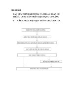
constitutes mainly of the following components See
figure a.
• ZnO varistors (blocks)
• Internal parts
• Pressure relief devices (normally not included for
arresters with polymer-housings since these do not
include any enclosed gas volume. The short-circuit
capability of a polymer-housed arrester must
therefore be solved as an integrated part of the
entire design).
• Housing of porcelain or polymeric material with
end fittings (flanges) of metal
• A grading ring arrangement where necessary
3
L
ine
t
erminal
C
ap
I
nner
i
nsulator
O
uter
i
nsulator
Z
nO
b
locks
S
pacer
F
ibreglass
loops
Y
oke
B
ase
Figure A:Principal designs of porcelain- and polymer-housed ZnO surge arresters. The most important
component in the arresters is of course the ZnO varistor itself giving the characteristics of the arrester. All
other details are used to protect or keep the ZnO varistors together
2.1 Z
NO VARISTORS
The zinc oxide (ZnO) varistor is a densely sintered
block, pressed to a cylindrical body. The block
consists of 90% zinc oxide and 10% of other metal
oxides (additives) of which bismuth oxide is the most
important.
During the manufacturing process a powder is
prepared which then is pressed to a cylindrical body
under high pressure. The pressed bodies are then
sintered in a kiln for several hours at a temperature of
1100 °C to 1 200 °C. During the sintering the oxide
powder transforms to a dense ceramic body with
varistor properties (see figure b) where the additives
will form an inter-granular layer surrounding the zinc
oxide grains.
These layers, or barriers, give the varistor its non-
linear characteristics. Aluminium is applied on the end
surfaces of the finished varistor to improve the current
carrying capability and to secure a good contact
between series- connected varistors. An insulating
layer is applied to the cylindrical surface thus giving
protection against external flashover and against
chemical influence.
Figure B: Current-voltage characteristic for a ZnO-
varistor.
4
2.2 I
NTERNAL PARTS OF A SURGE ARRESTER AND
DESIGN PRINCIPLES FOR HIGH SHORT-CIRCUIT
CAPABILITY
For all the different types of housings, the ZnO blocks
are manufactured in the same manner. The internal
parts, however, differ considerably between a
porcelain-housed arrester and a polymer-housed
arrester. The only thing common between these two
designs is that both include a stack of series-connected
zinc oxide varistors together with components to keep
the stack together but there the similarities end.
A porcelain-housed arrester contains normally a large
amount of dry air or inert gas while a polymer-housed
arrester normally does not have any enclosed gas
volume. This means that the requirements concerning
short-circuit capability and internal corona must be
solved quite differently for the two designs.
There is a possibility that porcelain-housed arresters,
containing an enclosed gas volume, might explode due
to the internal pressure increase caused by a short-
circuit, if the enclosed gas volume is not quickly
vented. To satisfy this important condition, the
arresters must be fitted with some type of pressure
relief system.
In order to prevent internal corona during normal
service conditions, the distance between the block
column and insulator must be sufficiently large to
ensure that the radial voltage difference between the
blocks and insulator will not create any partial
discharges.
Polymer-housed arresters differ depending on the type
of design. Presently these arresters can be found in one
of the following three groups:
I. Open or cage design
II. Closed design
III.Tubular design with an annular gas-gap between
the active parts and the external insulator
In the first group, the mechanical design may consist
of loops of glass-fibre, a cage of glass-fibre weave or
glass-fibre rods around the block column. The ZnO
blocks are then utilised to give the design some of its
mechanical strength. A body of silicon rubber or
EPDM rubber is then moulded on to the internal parts.
An outer insulator with sheds is then fitted or moulded
on the inner body. This outer insulator can also be
made in the same process as used for the inner body.
Such a design lacks an enclosed gas volume. At a
possible internal short-circuit, material will be
evaporated by the arc and cause a pressure increase.
Since the open design deliberately has been made
weak for internal overpressure, the rubber insulator
will quickly tear, partly or along the whole length of
the insulator. The air outside the insulator will be
ionised and the internal arc will commutate to the
outside.figure m illustrates this property vividly.
Surge arresters in group II have been mechanically
designed not to include any direct openings enabling a
pressure relief during an internal short-circuit. The
design might include a glass-fibre weave wounded
directly on the block column or a separate tube in
which the ZnO blocks are mounted. In order to obtain
a good mechanical strength the tube must be made
sufficiently strong which, in turn, might lead to a too
strong design with respect to short-circuit strength.
The internal overpressure could rise to a high value
before cracking the tube which may lead to an
explosive failure with parts thrown over a very large
area. To prevent a violent shattering of the housing, a
variety of solutions have been utilised, e.g., slots on
the tubes.
When glass-fibre weave, wound on the blocks to give
the necessary mechanical strength, is used, an
alternative has been to arrange the windings in a
special manner to obtain weaknesses that may crack.
These weaknesses ensure pressure relief and
commutation of the internal arc to the outside thus
preventing an explosion.
The tubular design finally, is designed more or less in
the same way as a standard porcelain arrester but
where the porcelain has been substituted by an
insulator of a glass-fibre reinforced epoxy tube with an
outer insulator of silicon- or EPDM rubber.
The internal parts, in general, are almost identical to
those used in an arrester with porcelain housing with
an annular gas-gap between the block column and the
insulator. The arrester must, obviously, be equipped
with some type of pressure relief device similar to
what is used on arresters with porcelain housing.
This design has its advantages and disadvantages
compared to other polymeric designs. One advantage
is that is easier to obtain a high mechanical strength.
Among the disadvantages are, e.g., a less efficient
cooling of the ZnO blocks and an increased risk of
exposure of the polymeric material to corona that may
5
occur between the inner wall of the insulator and the
block column during external pollution. This latter
problem can be solved by ensuring that the gap
between the block column and insulator is very large
but this leads to a costly and thermally even worse
design.
Polymer-housed arresters lacking the annular gas-gap
normally do not have any problem with corona during
normal service conditions in dry and clean conditions.
The design must be made corona-free during such
conditions and this is normally verified in a routine
test. However, during periods of wet external pollution
on the insulator the radial stresses increase
considerably. This necessitates that the insulator must
be free from cavities to prevent internal corona in the
material which might create problems in the long run.
The thickness of the material must also be sufficient to
prevent the possibility of puncturing of the insulator
due to radial voltage stresses or material erosion due to
external leakage currents on the outer surface of the
insulator. The effects of external pollution are dealt
with later on in the paper. See art. 3.2.5.
2.3 S
URGE ARRESTER HOUSING
As mentioned before, the housings of the surge
arresters traditionally have been made of porcelain but
the trend today is towards use of polymeric insulators
for arresters for both distribution systems as well as for
medium voltage systems and recently even for HV and
EHV system voltages.
There are mainly three reasons why polymeric
materials have been seen as an attractive alternative to
porcelain as an insulator material for surge arresters:
• Better behaviour in polluted areas
• Better short-circuit capability with increased safety
for other equioment and personnel nearby.
• Low weight
• Non-brittle
It is quite possible to design an arrester fulfilling these
criteria but it is wrong, however, to believe that all
polymer-housed arresters automatically have all of
these features just because the porcelain has been
replaced by a rubber insulator. The design must be
scrutinised carefully for each case.
Polymeric materials generally perform better in
polluted environments compared to porcelain
insulator. This is mainly due to the hydrophobic
behaviour of the polymeric material, i.e., the ability to
prevent wetting of the insulator surface. However, it
shall be noted that not all of the polymeric insulators
are equally hydrophobic.
Two commonly used materials are silicon- and EPDM
rubber together with a variety of additives to achieve
desired material features, e.g., fire-retardant, stable
against UV radiation etc. Polymeric materials can
more easily be affected by ageing due to partial
discharges and leakage currents on the surface, UV
radiation, chemicals etc. compared to porcelain which
is a non-organic material. Both silicon- and EPDM
rubber show hydrophobic behaviour when new. The
insulator made of EPDM rubber, however, will lose its
hydrophobicity quickly and is thus often regarded as a
hydrophilic insulator material.
Hydrophobicity results in reduced creepage currents
during external pollution, minimising electrical
discharges on the surface; thereby reducing the effects
of ageing phenomena. The material can lose its
hydrophobicity if the insulator has been subjected to
high leakage currents during a long time due to severe
pollution, e.g., salt in combination with moisture. The
silicon rubber, though, will recover its hydrophobicity
through diffusion of low molecular silicones to the
surface restoring the original hydrophobic behaviour.
The EPDM rubber lacks this possibility completely
and hence the material is very likely to lose its
hydrophobicity completely with time.
A safe short-circuit performance is not achieved only
by using a polymeric insulator. The design must take
into consideration what might happen at a possible
failure of the ZnO blocks. This can be solved,
depending on the type of design, in different ways as
described in article 2.2.
Unfortunately, lack of relevant standardised test
procedures for polymer-housed arresters has made it
possible to uncritically use test methods only intended
for porcelain designs
[1,2]. This has led to the belief,
incorrectly, that ”all” polymer-housed arresters,
irrespective of design, are capable of carrying
enormous short-circuit currents.
The work within IEC to specify short-circuit test
procedures suitable for polymer-housed arresters will
be finalised soon [3]. The test procedures most likely
to be adopted will, hopefully soon enough, clean the
market from polymer-housed arresters not having a
sufficient short-circuit capability.
6
The possible weight reduction compared to porcelain
housed arresters can be considerable. As an example
an arrester with porcelain insulator for a 550 kV
system voltage has a mass of approximately 450 kg. A
polymer-housed arrester for conventional up-right
erection, with the same rated voltage, can be designed
with a mass of approximately 275 kg. If suspended
mounting is accepted, the weight can further be
reduced to a total mass of only approximately 150 kg!
For long arresters for HV and EHV application, the
desired increase in the mechanical strength of the
housing is obtained by using additional stays of
polymer material as can be seen in figure c.
Since the polymeric insulator, commonly silicon- or
EPDM rubber, does not have the mechanical strength
to keep the ZnO column together, other insulator
materials must be used in the design. The most
commonly used material is glass-fibre. There are
several types of mechanical designs, e.g., cross-
winding, tubes and loops.
Two main possibilities exist to combine the glass-fibre
design and the insulator; firstly, the glass-fibre design
can be moulded directly into the rubber insulator and
secondly, the boundary between the glass-fibre and the
rubber insulator is filled with grease or a gel, generally
of silicon. It is of great importance that no air pockets
are present in the design where partial discharges
might occur leading to destruction of the insulator
with time. Penetration of water and moisture must also
be prevented which sets high requirements on the
sealing of the insulator at the metallic flanges and
adherence of the rubber to all internal parts in case the
rubber is moulded directly on the inner design.
2.4 G
RADING RINGS
Surge arresters for system voltages approximately 145
kV and above must normally be equipped with one or
more metallic rings hanging down from the top of the
arrester. The function of these rings is to ensure that
the electrical field surrounding the arrester is as linear
as possible. For very high system voltages, additional
rings are used to prevent external corona from the
upper metallic flange and from the line terminal.
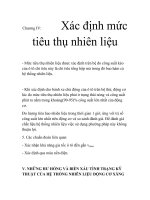
3. DESIGN
3.1 DESIGNING FOR CONTINUOUS STRESSES
3.1.1 CONTINUOUS OPERATING VOLTAGE
Denoted as Uc in accordance with the IEC standard,
Figure C: Polymer-housed surge arrester for
550 kV system voltage. The surge arrester is
designed to meet extreme earthquake
requirements in the Los Angeles area (USA).
7
it is the voltage stress the arrester is designed to
operate under during its entire lifetime. The arrester
shall act as an insulator against this voltage. The
entire voltage is across the ZnO varistors and these
must be able to maintain their insulating properties
during their entire lifetime.
The continuous operating voltage for AC surge
arresters is mainly at power frequency, i.e., 50 Hz to
60 Hz with some percent of superimposed harmonics.
For other applications, e.g. HVDC, the waveform of
the voltage might be very complicated. The voltage
might also be a pure DC voltage. It must be verified,
therefore, for all applications that the ZnO varistors are
able to withstand the actual voltage under their
technical and commercial lifetime which normally is
stated to be 20 to 30 years.
The basis for the dimensioning is the result from
ageing procedures where possible ageing effects are
accelerated by performing tests at an elevated
temperature of 115 °C. For porcelain-housed arresters
filled with air (sometimes nitrogen) it is not necessary
to encapsulate the blocks during the test. For
polymeric arresters, where the ZnO blocks are in direct
contact with rubber, silicon grease or any other
polymeric material, the ageing test must be made
including these additional materials to verify that there
are no negative effects, i.e., ageing of the blocks from
the other materials.
The normal development of power losses for ZnO
varistors is shown in figure d.
At voltage levels below the knee-point the ZnO block
can be seen as a capacitor which is connected in
parallel to a non-linear resistor. The resistance is both
temperature- and frequency- dependent.
It is not sufficient just to check the behaviour of the
ZnO varistor alone. The arrester must be seen as an
integrated unit. The ability of the arrester housing to
transfer heat must be considered and adjusted to the
power losses of the ZnO varistors. This consideration
must be made for different service conditions with
respect to voltage, temperature and frequency to
ensure that the continuous block temperature does not
considerably exceed the ambient temperature.
If the power losses would increase with time, i.e., the
ZnO blocks “age”, this must be accounted for in the
dimensioning of the arrester.
figure e principally shows how the capability of the
arrester housing to transfer heat and the temperature-
dependent voltage-current characteristic in the leakage
current region of a ZnO varistor results in a working-
temperature at a certain ambient temperature and
certain chosen voltage stress (A in the Figure).
An upper maximum temperature also exists (B in
figure e) above which the design is no longer
thermally stable for a given continuous operating
voltage. If the temperature would increase above this
value due to, e.g., transient or temporary overvoltages,
the temperature will continue to increase until the
arrester fails. The maximum designated Uc for an
0 100 200 300 400 500 600 700 800 900 1000 1100 1200
Time (hours)
0
0.2
0.4
0.6
0.8
1
1.2
Relative power losses P/Po (Po=power losses after 1.5 hour)
Figure D:Typical power losses during an
accelerated ageing test at 115
°
C and applied
voltage ratio 0.97 times the reference voltage. Note
that the test sample includes the polymer insulator
moulded on to the ZnO blocks.
40 60 80 100 120 140 160 180 200
Varistor temperature - degrees C
0
1
2
3
4
5
Thermal characteristics of housing
Power losses at 0.6*Uref
Power losses at 0.7*Uref
Power losses at 0.8*Uref
Power losses at 0.9*Uref
Relative power losses
A
B
Figure E: Thermal characteristics of a surge arrester
housing and power losses for a ZnO varistor at
different relative voltage stresses (ambient
temperature +40 °C, Uref = reference voltage)
8
arrester must thus be chosen with respect to possible
power losses due to ageing, maximum ambient
temperature, estimated energy absorption capability
for transient overvoltages and temporary overvoltage
(TOV) capability after the energy absorption.
When losses and possible ageing of the ZnO blocks
are judged, a consideration of the complete arrester
design must be made. The local voltage stress along a
long arrester for high system voltages might deviate
considerably from the average voltage stress. This, in
turn, might lead to local heating of the upper part of
the arrester and possible ageing of the ZnO blocks
subjected to this high voltage.
It is essential, therefore, to distinguish between what
the ZnO blocks can be subjected to without any
encapsulation and how the design actually can be
made taking into consideration that the ZnO blocks are
encapsulated in a long arrester.
To ensure that the maximum stresses does not exceed
given design criteria, the necessity of a suitable voltage
grading must be considered. This is best accomplished
with computer programs for electrical field
calculations.
3.1.2 V
OLTAGE GRADING
During normal operation conditions and operation
voltages the ZnO blocks act like capacitors. The
voltage across the ZnO blocks, therefore, will be
determined by the self-capacitance of the blocks as
well as stray capacitance to the surroundings. For a
long ZnO column, the self-capacitance of the ZnO
blocks quickly becomes insufficient to ensure an even
voltage distribution between the blocks. The surge
arrester, therefore, must be equipped with some type of
voltage grading. This can be achieved by additional
grading capacitors and/or grading rings. Provision of
grading rings is the most common way improving the
voltage distribution.
The risk of local heating of the ZnO blocks (hot-spots),
with consequent reduced energy absorption capability
of the arrester, increases if the voltage distribution is
not reasonably uniform along the whole arrester. Type
tests in accordance with standards, to verify that the
ZnO blocks are stable during sufficiently long time,
are not valid either if the actual voltage stress on the
arrester during actual service is allowed to exceed the
applied voltage stress in the type tests.
An actual surge arrester installation constitutes a
three-dimensional problem with three-phase voltages
involved together with certain stipulated minimum
distances between phases and to grounded (earthed)
objects. All this must be considered when making a
calculation. Not to consider the influence of adjacent
phases, for example, will lead to an underestimation of
the maximum uneven voltage distribution by up to 10
%.
System voltage 145 kV System voltage 245 kV System voltage 420 kV System voltage 800 kV
Figure F: Examples on different grading ring arrangements for different system voltages. Note that the arresters
are not shown to scale.
9
figure f shows the typical grading ring arrangement
for arresters for different system voltages ( 145 to 800
kV).
Without using any components at all to improve the
voltage grading, e.g., grading capacitors or suspended
grading rings, the voltage across individual ZnO
blocks at the line-end of a long arrester will be above
the knee-point of the current-voltage characteristics,
i.e., where the blocks start to conduct large currents.
This current is determined by the applied voltage and
the total stray-capacitance of the arrester to earth and
can, for high voltage arresters, be considerable.
Big metallic electrodes, e.g., metallic flanges or rings
to reduce corona without any suspension from its
electrical contact point to the arrester, increases the
stray-capacitance to earth amplifying the uneven
voltage distribution.
3.1.3 M
ECHANICAL DESIGN OF POLYMER-HOUSED
ARRESTERS
Continuous stresses on polymeric materials must be
selected with respect to the material behaviour of the
polymer. Many of these characteristics are strongly
dependent on temperature and load time. Polymeric
materials becomes softer at higher temperatures with a
higher degree of creeping (cold flowing), at cold
temperatures the material becomes brittle.
It therefore is of great importance that the arrester
design is tested with different temperature and load
combinations to verify that all possible sealings
operate adequately in the entire temperature interval.
Composite materials, e.g., glass-fibre joined in a
matrix with epoxy or other polymeric materials,
exhibit behaviour changes at high loading. The rate of
this material degradation is determined by temperature,
applied force, velocity of the applied force, humidity
and the time during which the load is applied. It is not
sufficient, therefore, just to dimension the arrester with
respect to its breaking force but consideration must
also be taken to how the arrester withstands cyclical
stresses.
Up to a certain mechanical load, the fibres of the
composite material will not break (degrade). This is
the maximum load, defined in terms of the maximum
usable bending moment (MUBM), that can be applied
continuously in service. This value has very little
spread between different housings of the same type
unlike that for porcelain for which large safety margins
are recommended due to the spread in the breaking
moment.
The MUBM limit is best verified by measuring the
acoustic emission to determine what forces might be
applied on the arresters without long-term degradation
of the composite materials. The MUBM value should
be compared with the “static load” limit for porcelains
which is 40% of the minimum breaking moment (as
defined in DIN 48113).
At a value slightly above the MUBM, some fibres may
start to break. When enough fibres break, there is a
small change in the mechanical properties when
stressed above MUBM again. A permanent deflection
results when sufficient number of fibres are broken.
Thus small overloads beyond MUBM have no
significant impact on the service performance.
The new IEC standard, [3] will include a test where
the arrester is subjected to both thermal as well as
mechanical cycling. After the cycling, the arrester is
placed in boiling water for 42 hours where moisture is
given time and possibility to penetrate the arrester.
Electrical measurements are made both before and
after the test sequences to verify that the specimen has
not absorbed any moisture. If the electrical
characteristic of the arrester has changed during the
tests, the most likely conclusion is that moisture has
penetrated into the design which might imply that the
arrester no longer fulfils the original requirements.
Since the polymeric arresters are elastic, temporary
loads, like short-circuit forces and earthquake forces,
can be looked upon differently compared to rigid
bodies like porcelain insulators. The reason for this is
that the forces do not have time to act fully due to the
elasticity of the material and mass inertia, i.e., the
forces are spread in time leading to that the arrester
will not encounter any high instantaneous values.
These advantages , combined with a design with small
mass participation, have been fully utilised for the 550
kV arrester shown in figure c. This arrester withstands
a ground horizontal acceleration of 0.5 g
corresponding to the highest seismic demands as per
IEEE/ANSI standards without any problems at all.
3.1.4 I
NTERNAL PARTS
A low corona (partial discharge, PD) level is desirable
for all apparatus designs intended for high voltage
applications during normal service conditions.
Porcelain arresters, though, will have large voltage
10
differences between the outside and inside of the
arrester during external pollution and wetting of the
porcelain surface. To fully avoid corona under such
conditions will not give technically and economically
defensible designs. Instead the internal parts including
the ZnO blocks must be able to withstand these
conditions.
For polymeric arresters, lacking such annular space in
the design, the voltage difference is entirely across the
rubber insulator. In order to avoid puncturing of the
insulator the rubber must be sufficiently thick. It is
also very important that the insulator does not have
any air pockets which might give internal corona
which, with time, may destroy the insulator.
The allowable voltage stress across the material is
proportional to the length of the insulator. A longer
insulator, therefore, requires that the thickness of the
material is proportionally increased with respect to the
increase in length.
Another solution is to reduce the height of the
individual units in a multi-unit arrester, since the
maximum voltage across each unit is limited by the
non-linear current-voltage characteristic of the ZnO
blocks. In order to verify the withstand against these
type of stresses, IEC has proposed a long-time test
under continuous operating voltage with continuously
applied saltfog [3]. The test must be made on the
longest arrester housing for at least 1 000 hours.
3.2 D
ESIGNING FOR NON-CONTINUOUS STRESSES
3.2.1 TEMPORARY OVERVOLTAGES
TOV may occur in networks at, e.g., earth-faults. This
is a voltage which, by definition, is above Uc and
normally will last from some few periods up to some
seconds. In certain isolated systems, the duration of an
earth-fault may last some days. The TOVs are
normally preceded by a switching surge.
A ZnO arrester is considered to have withstood a TOV
if:
a) the ZnO-blocks are not destroyed due to energy
under the TOV i.e. cracking, puncturing or
flashover of the blocks does not occur.
b) the surge arrester is thermally stable against Uc
after cessation of the TOV
Since the leakage current through the arrester is
temperature-dependent, see also figure b, fulfilling b)
above is also dependent on the final block
temperature. If, for example, due to a switching surge,
the arrester already has a high starting temperature
before being subjected to a TOV, it will naturally have
a lower overvoltage capability.
This is exemplified in figure g showing the ability of a
ZnO arrester to withstand overvoltages with or without
a preceding energy absorption. The lower curve is
valid for an arrester which has been subjected to
maximum allowable energy, e.g., from a switching
surge prior to the TOV. The upper curve is valid for an
arrester without prior energy duty.
With ZnO arresters the TOV amplitudes are normally
at, or immediately above, the knee-point of the current-
voltage characteristic. If the arrester is designed
fulfilling the IEC standard, it shall be able to withstand
a TOV equal to the rated voltage of the arrester for at
least 10 seconds after being subjected to an energy
injection corresponding to two line discharges as per
relevant line discharge class of the arrester.
The TOV is generally regarded as a stiff voltage
source, i.e., the surge arrester cannot influence the
voltage amplitude. For a dimensioning to fulfil a
certain TOV level, the varistor characteristic must be
chosen so the current through the arrester, and
consequently the energy dissipation, will not result in a
temperature above the thermal instability-point.
The TOV capability given for a certain surge arrester
should always be assumed with a stiff voltage source.
However, if this is not the case, the TOV capability of
the arrester, in general, is significantly higher.
0.1 1 10 100 1000 10000 100000
Duration of TOV in seconds
0.7
0.8
0.9
1
1.1
1.2
1.3
Without prior energy
With prior energy = 4.5 kJ/kV (Ur)
TOV Strength factor (T
r)
U
c
(MAX)=0.8xU
r
Figure G: TOV capability for polymer-housed line
discharge class 3 arrester as per IEC
11
An important parameter concerning the dimensioning
for TOVs is to accurately control the knee-point
voltage since the non-linearity of the characteristic is
in its extreme in the TOV range. This is best made by
defining a reference voltage close to the knee-point on
the voltage-current characteristics and then, in routine
tests, checking that every arresters has a reference
voltage above a guaranteed minimum voltage.
A distinct advantage with polymer-housed arresters is
the superior heat transfer which leads to shorter
cooling times and possible higher Uc or acceptance of
a higher ambient temperature (above IEC stipulations)
as is often the case in tropical desert climates. This is
illustrated in figure h. The voltage after the energy
injection was purposely increased to induce a thermal
runaway in the porcelain-housed sample. At the same
conditions, the polymer-housed sample was thermally
stable.
A manufacturer is free to assign any data for the
arresters. A given arrester with ZnO blocks capable to
absorb high energies, therefore, could be assigned a
very high line discharge class with low TOV capability
or, on the contrary, a low line discharge class with
high TOV capability.
3.2.2 T
RANSIENT OVERVOLTAGES - ENERGY
CAPABILITY
- CURRENT WITHSTAND STRENGTHS
A surge arrester may in service be subjected to
different energy impulses originating from, e.g.,
lightning, faults in the net-work and switching of lines
and/or capacitor banks.
The arresters must be designed in such a way that the
ZnO blocks will withstand the energy or current
without failing. Additionally the arrester must be able
to withstand the energy thermally, i.e., it must be able
to cool against Uc after an energy absorption.
High voltage arresters are normally designed for a
specific line discharge class. figure i shows relative
energies in kJ/kV rated voltage for the different line
discharge classes. The intention with the classification
is naturally that a higher class should represent a
higher energy capability for a given arrester. This is
true, however, only if the ratio between the switching
impulse residual voltage to the rated voltage of the
arrester is approximately a factor of two. If the residual
voltage is much higher, the line discharge class will
become a useless quality measure.
The rated energy is often given in catalogues in kJ/kV
rated voltage. Since the ZnO blocks normally are able
to withstand sufficiently higher energies for longer
times, seconds, compared to shorter times, e.g., milli
seconds, the expression itself is meaningless if, at the
same time, the shortest time for which the arrester can
be subjected to the given energy is not stated.
A surge arrester may contain a large number of ZnO
blocks and if just one of these blocks fails during an
overvoltage the probability for a failure of the
complete arrester is significant. The failure rate for a
single ZnO varistor, therefore, must be extremely
small to obtain a high reliability of the complete
arrester. One way to guarantee a low failure rate is to
routine-test all manufactured varistors with an energy
considerably exceeding the corresponding varistor
energy at the given rated energy for the arrester.
1.0 1.4 1.8 2.2 2.6 3.0
RELATIVE PROTECTIVE LEVEL Ua/Ur
0
1
2
3
4
5
6
7
SPECIFIC ENERGY kJ/kV (Ur) (IEC)
CLASS 1
CLASS 2
CLASS 3
CLASS 4
CLASS 5
Figure I: Relative energy stresses for different line
discharge classes according to IEC
0 5 10 15 20 25 30 35
Time (minutes)
60
100
140
180
220
Porcelain housing
Polymer housing
Temperature (degrees C)
First discharge
Second discharge
Figure H: Oscillogram from an operating duty test
showing the superior cooling properties of polymer
housing.
12
As mentioned before, a high voltage arrester is
normally designed in compliance with a chosen line
discharge class as per IEC with respect to energy. For
non-standard stresses, e.g., capacitor discharges or
high energies due to lightning, the design is normally
made with a lower energy stress per varistor.
The ZnO blocks, apart from withstanding the energy
from current impulses, also must have a sufficiently
high dielectric withstand ensuring that the voltage
across the block will not result in a puncture of or a
flashover across the block. To ensure a sufficient
insulation withstand margin for normal stresses, the
ZnO blocks, including all internal parts in a high
voltage arrester, are dimensioned to withstand current
impulses with an amplitude of at least 100 kA having a
wave form of 4/10 µs. Requirements with very high
energy absorption capability cannot be solved by
using ZnO blocks with ever larger volumes but must
be solved by connecting ZnO varistor columns and
arresters in parallel.
To ensure that such designs will operate correctly
during service, a very careful procedure is required to
ensure a good current sharing between the block
columns connected in parallel. Furthermore, possible
changes of the block characteristic due to the normal
applied service voltage as well as energy- and voltage
stresses must be extremely small.
From protection perspective, it is acceptable that the
residual voltage decreases due to repeated current
impulses. When parallel connection of ZnO blocks is
utilised, the acceptable deviations, however, are much
lower than what the IEC standard permits (+/- 5%).
3.2.3 T
RANSIENT OVERVOLTAGES - EXTERNAL
INSULATION
In contradiction to other apparatus, the insulation level
for surge arresters does not need to fulfil a
standardised insulation class since the arrester
effectively will protect its own insulation against
overvoltages. Distance effects need not be considered.
Instead, the Standards stipulate a specific safety
margin between the residual voltage of the arrester and
the voltage withstand level of its external insulation.
The complete arrester, including possible grading
rings, therefore must be designed to give a reasonable
safety margin against external flashover during an
overvoltage.
IEC requires the following minimum external
insulation levels for an arrester housing:
Arresters with a rated voltage < 200 kV
a) For a standard lightning impulse, 1.3 times the
residual voltage at the nominal current with a wave
shape 8/20µs
b) For power frequency, 50/60 Hz (peak value), 1.06
times the residual voltage at the classifying current
with a wave shape 30/60µs
Arresters with a rated voltage ≥ 200 kV
a) For a standard lightning impulse, 1.3 times the
residual voltage at the nominal current with a wave
shape 8/20µs
b) For a standard switching impulse, 1.25 times the
residual voltage at the classifying current with a
wave shape 30/60µs
The tests with switching impulses and power
frequency are made as wet tests if the arresters are to
be installed outdoors. With the specified margins to
the protection characteristic of the arrester, an
acceptable low risk for external insulation failure is
obtained up to an installation altitude of 1 000 m
above sea level as required by IEC.
All distances between the different parts of a surge
arrester, e.g., grading rings to flanges or between
flanges of the individual units or distances to earthed
(grounded) equipment and to adjacent phases, must be
verified with respect to voltage stress and voltage
withstand. The complete arrester should preferably be
tested to verify the withstand values even though the
present IEC standard does not so stipulate [2].
The ZnO blocks cannot be included during these tests
since test equipment capable of generating the required
high currents does not exist. In order to emulate actual
service conditions as much as possible, the ZnO blocks
should, for a multi-unit arrester, be replaced by grading
capacitors. If the ZnO blocks are removed without any
replacement for the voltage grading, the test result may
not be conservative.
3.2.4 T
RANSIENT OVERVOLTAGES - PROTECTIVE
FUNCTION
The arrester shall, for an expected maximum current,
limit an overvoltage to a level well below the
insulation withstand level of the protected equipment.
The protective characteristic for a ZnO varistor is
slightly dependent on the steepness of the expected
current. figure j shows the characteristic for a specific
arrester for the three different current shapes given in
13
the arrester Standards. As can be noted from the
diagram, the protection level for currents having a
front time of 1 µs are approximately 10% higher
compared to currents with a wave form 8/20 µs or
longer. However, even more important than this
marginal increase, for currents in the µs region, is the
effect of positioning the arrester in relation to the
protected equipment and the length of the connections.
There is also an effect due to the arrester height.
In order to obtain an efficient protection against fast
transients, e.g., backflashover close to a substation,
large margins, therefore, are required between the
protection level of the surge arrester and the protected
equipment’s insulation level.
ZnO blocks with larger diameter has normally a better
protection level with maintained overvoltage
capability. A better protection level gives also
automatically a better energy capability.
3.2.5 E
XTERNAL POLLUTION
External pollution may influence a surge arrester as
follows:
• Possibility of internal corona
• External flashover
• Heating of the ZnO blocks
• Tracking and erosion of insulator (polymer-housed
arresters)
0.1 1 10 100
Current (kA)
70
80
90
100
110
120
130
140
Lightning (8/20 micros. current wave)
Switch (30/60 micros. current wave)
Steep (1/2 micros. current wave)
Max residual voltage in per cent of residual voltage at 10kA 8/20 impulse
Figure J: Protective characteristic for a polymer-
housed surge arrester with nominal discharge current
20 kA. The protection level is given in % of the 10 kA
level which is checked in a routine test
The problems for arresters with porcelain housings
installed in extremely polluted areas have been solved
by greasing the insulator thus improving the pollution
performance. The aim of the greasing is to reduce the
leakage currents on the insulator surface. Hydrophobic
materials, like silicon rubber, give a similar effect.
This is one strong motive why silicon rubber has been
seen as an attractive insulator material.
A common conception is that polymer-housed
arresters have a better pollution performance compared
to porcelain. However, a more correct statement
should be that hydrophobic materials have better
performance in polluted areas due to reduced leakage
currents. EPDM rubber, that loses its hydrophobic
properties quickly, must be designed in the same
manner as porcelain from pollution point of view.
It is very difficult to avoid internal corona, as
discussed previously, during severe external pollution
on arresters containing an annular gap between the
ZnO blocks and the insulator as in the case of
arrangements similar to porcelain-housed arresters.
The design of such arresters, therefore, must be able to
withstand corona during such occasions.
Some rules-of-thumb for designs like these are:
• "No" corona in dry conditions
• Minimise the use of organic materials. When
organic materials are used they must have been
thoroughly tested and subjected to a realistic
corona test
• Prevent the possibility of electrical discharges
directly on to the ZnO blocks
Concerning polymer-housed arresters, large radial
voltage stresses may occur between the blocks and the
outside of the insulator during severe external
pollution. It is very important, therefore, that the
rubber insulator is thick enough to avoid a puncture of
the insulator. If such a design includes large air
pockets or cavities, corona might occur that eventually
leads to an arrester failure. As mentioned before, a
supplement to the IEC standard will most likely be
issued with requirements on a 1 000 hours test with
continuous saltfog to verify the long-term stability of
the insulation [3].
To avoid external flashover the creepage distance of
the arrester, i.e. the shed-form and the length, is
designed in compliance with the same criteria valid for
other insulation at the actual site.
Possible thermal stresses are determined by the
leakage currents that might be present on the outer
surface of the insulator. For porcelain arresters it has
been shown that the integral of the leakage current, i.e.
the charge, can be regarded as independent of the
14
creepage distance but it is approximately linearly
dependent on the diameter of the porcelain. An
insulator with a larger diameter thus may give rise to
higher thermal stress during conditions with external
pollution, provided the service conditions otherwise
are the same.
For applications requiring arresters with parallel
housings and several units connected in series, the
general rule is that the units should not be connected in
parallel except at the top and bottom. This is because,
in such an event, the ZnO blocks in one unit could
conduct the external leakage current from all of the
parallel connected arresters. Since the ZnO blocks
have a negative temperature coefficient in the leakage-
current region, a heating of one unit will lead to a
reduction of the voltage characteristic with subsequent
increase of the current. An increased current through
the unit leads to higher power losses with increased
temperature etc. Not even a careful current-sharing test
of the arrester units will be of any help below the knee-
point of current-voltage characteristic. However, above
the knee-point the characteristic has a slightly positive
temperature coefficient.
Improvement in a ZnO arrester’s external pollution
withstand, during otherwise similar conditions, is
obtained by:
• Higher rated voltage, i.e., a higher TOV capability
• Higher energy capability, i.e., normally a larger
block volume
• Improved heat conduction - higher thermal stability
point
• Lower power losses at continuous operating
voltage
• Lower leakage currents on the insulator surface
Lower leakage currents on the insulator surface is
achieved by a hydrophobic surface. figure k shows
leakage currents as measured on a porcelain insulator
and a polymeric arrester for 145 kV systems having a
silicon rubber insulator. The values are taken from an
on-going test at NGC’s test station at Dungeness at the
English Channel. As can be noted, the amplitudes of
the leakage currents are roughly half to a third of the
corresponding leakage currents on the surface of the
porcelain insulator during this specific measuring
interval.
All the tests carried out and the operating experience
gained so far indicate that the external creepage
distance for polymer-housed arresters could be shorter
than that for equivalent porcelain-housed arresters by
one class (as defined in IEC 815). This would be of
great advantage for use in desert climates where the
need for the necessary high creepage leads, at present,
to expensive and difficult designs in porcelain
housings.
0
5
10
15
20
25
30
C
u
r
r
e
n
t
(
m
A
)
Arrester with silicone insulator
Porcelain insulator
Daily maximum currents in a 16 days period at
Dungeness test station
Figure K: The leakage currents for 145 kV polymer-
housed surge arrester and porcelain insulator at
Dungeness test station. The leakage current for the
arrester includes an internal leakage current of
around 1 mA. The creepage distance for the polymeric
arrester is 5 148 mm and 4 580 mm for the porcelain
insulator.
3.3 D
IMENSIONING FOR HIGH SHORT-CIRCUIT
PERFORMANCE
As mentioned previously, the primary duty of a surge
arrester, viz. to protect other equipment under all
circumstances, gives a slightly higher risk of failure
compared to other high voltage apparatus, which is
accepted generally.
Since the risk of failure is not negligible, specific
requirements are set on arresters to ensure that
possible failures will not give consequential damages
on other equipment, or, lead to unacceptable risk for
people. Tests, where the internal parts are deliberately
short-circuited, are also required, therefore, in the
Standards. From design point-of-view, the aim is to
ensure that the arrester housing is not scattered after a
possible overloading.
In the existing Standard dealing with short-circuit
tests, IEC 99-1 (being the old surge arrester Standard
for gapped SiC arresters), it is taken for granted that an
15
arrester fulfilling a certain current class, with respect
to short-circuit performance, automatically also fulfils
lower current requirements. Recently it has been found
that this is not always the case. A design might have
”grey zones” if only tested with the highest possible
current amplitude. A test made on the longest insulator
used for a specific arrester design, is also considered to
cover shorter insulators.
Discussions are going on within IEC on how the
internal short-circuit shall be made before applying of
the short-circuit current. A thin fuse-wire, arbitrary
located, might not represent an actual fault-event,
especially if the design is non-symmetrical with
respect to arrangement of the pressure relief devices. It
has been discussed, therefore, to place the wire in a
location where it would represent the worst case for
different design types and this requirement will be
included in the Standard.
How to perform short-circuit tests on polymeric
arresters, with no internal channels for a pressure
relief, is another question discussed within IEC. As
mentioned previously, it is not possible to uncritically
apply test methods intended for porcelain arresters on
polymeric designs. To perform tests by arbitrarily
short-circuiting a polymeric arrester with a fuse-wire
located alongside the block column, inside the external
insulator, could result in that unsafe arresters are
believed to be completely safe.
A suggested revision of the IEC Standard will most
probably lead to tests on arresters at approximately
25%, 50% and 100% of the classifying short-circuit
current. How the tests are performed are so far only
defined in IEC 99-1 but a working group within IEC
(IEC TC37 WG4) is working to revise the test
procedure. The present tests shall be made with a high
current, 16 kA to 80 kA, as well as with a low current,
400 A to 800 A.
The test duration is 0.2 seconds during the high-
current test which reflects the time it takes a circuit
breaker to disconnect a fault. To avoid an explosion of
the arrester housing the internal arc must, in most
cases, be commutated to the outside of the arrester
within the first half-period of the short-circuit current.
Since this time is critical, a certain current amplitude is
defined for the first major loop of current, being 2.6
times the prospective symmetrical fault current.For the
low current test, 600 A to 800 A, the current is
maintained until opening of the pressure relief device
occurs, which shall take place within 1 second.
Figure L: A polymer-housed arrester prior to a short-
circuit test.
Figure M: The same arrester after a short-circuit test
at 50 kA sym
16
The most likely test procedure, according to IEC, will
give two possibilities, two test methods, to obtain an
internal short-circuit. The first method is to provoke a
short-circuit of the ZnO blocks by applying a
sufficiently high voltage on the arrester leading to an
electrical failure in two to eight minutes where after
the arrester shall be subjected to the short-circuit test
(high current) within five minutes. The second
alternative is to short-circuit the arrester with a thin
fuse-wire through a pre-drilled hole between the centre
and the periphery of the blocks. This latter method is
considered to be the worst-case model.
The pictures in Error! Reference source not found.
and Error! Reference source not found. show the
results of a short-circuit test at 50 kA , performed in
accordance with the proposed IEC standards.
4. VERIFICATION OF SURGE
ARRESTER DESIGN
Set requirements on a surge arrester and the design of
the same are considered to be satisfactory verified by
having the arrester subjected to the following tests:
• Residual voltage measurement at different current
amplitudes and wave-shapes
• Current impulse withstand tests
• Operating duty test
• Accelerated ageing test
• Artificial pollution test
• External insulation test
• Short-circuit test
• Mechanical test
The above tests are considered to be type tests (design
tests) but some of these may also be performed during
the manufacturing process and/or assembly as a part of
a manufacturer’s quality assurance. The protective
characteristic is verified during the various residual
voltage tests.
The reliability is checked through a number of
electrical and mechanical tests. An important part of
the electrical tests is the operating duty test in which
an arrester, or a pre-scaled model of the arrester, is
subjected to a combination of stresses representing
anticipated service stresses that an arrester might be
subjected to during its lifetime.
The lifetime is finally verified by subjecting the ZnO
blocks to an accelerated ageing test procedure.
Within IEC, TC37 is responsible for the
standardisation of surge arresters. The working group
responsible for the new Standard for gapless metal-
oxide arresters, IEC 99-4, is named IEC TC37 WG4.
This working group will continue its work also after
publishing of the new standard. The group shall
propose, among others, a test method for artificial
pollution on ZnO arresters, something that still is
lacking in the new Standard.
In the forthcoming Standard on polymer-housed
arresters, the test procedures will differ considerably
from previous tests on porcelain designs. A tightness
check will e.g., be required to verify that polymeric
arresters will not absorb moisture [3]. According to the
suggested test procedure, the arrester shall be
subjected to both mechanical and electrical tests before
immersed in boiling salt water. After the boiling, the
electrical tests will be repeated to verify that the
characteristic has not changed, something which could
indicate penetration of water.
5. SPECIAL APPLICATIONS OF
POLYMERIC ARRESTERS -
LIGHTNING & SWITCHING
PROTECTION OF TRANSMISSION
LINES
5.1 LIGHTNING PROTECTION OF TRANSMISSION
LINES
Transmission lines in the lower system voltage range,
70 kV - 245 kV, are often sensitive to lightning
overvoltages due to that:
• the insulation withstand is relatively low
• the transmission line often lacks shielding wires
• the footing impedance of the towers is high
• the transmission line lacks a continuous
counterpoise (earth wire)
Despite this, meshed networks with rapid re-
connection of faulty lines give satisfactory operation
safety. Short-time disturbances (around 0.5 seconds)
must be ignored, however,in radial nets as well as the
voltage drop during the fault time (around 0.1
second) occurring also in the meshed nets.
There are, however, some types of loads where even
the shortest disturbance is of greatest importance;
e.g. process industries as steel mills, paper mills and
refineries. For these loads, even a very short
disruption or voltage drop could lead to unacceptable
17
interruption of the on-going processes. The cost for
such an interruption is both the value of lost
production and the costs to re-start the production.
The accumulated sum for these costs can be very
high. In a de-regulated energy market such costs will
be more visible to the network operator than before,
since the buyer could set new, higher demands on
delivery security.
5.2 S
URGE ARRESTERS FOR TRANSMISSION LINE
PROTECTION AND THEIR DESIGN
What could then be done to increase the delivery
security with respect to faults caused by lightning?
The traditional methods to reduce the number of
faults caused by lightning have been:
• installation of shield wires
• improvement of the earthing impedance of the
towers
• increasing the insulation level
Unfortunately, implementing the above gives only
marginal improvements of the delivery security,
especially if the earthing conditions are difficult due
to a high earth resistivity.
A new possibility to reduce the number of line faults
caused by lightning is to install metal-oxide surge
arresters with polymeric insulators in parallel with
the line insulators. These transmission line arresters
(TLA) normally consist of standard polymer-housed
arresters together with a disconnecting device and
fastening equipment for installation on the line itself
or on the tower.
Transmission line arresters give complete protection
against lightning flashovers for the actual line
insulator. Insulators in adjacent phases and in other
towers, however, are not protected; why TLA should
be installed on all phases on the towers that are
intended to be protected.
In reality, TLA are seldom installed throughout an
entire line length but only in areas where lightning
gives most problems due to exposed position, bad
earthing conditions etc. Modern localisation systems
for lightning-storms in combination with traditional
fault statistics are excellent tools to identify towers
where TLA should be installed to be of the best
possible use.
The dimensioning of a TLA generally follows the
same criteria as for an arrester in a substation. It is of
great importance that the TLA is designed correctly
with respect to energy capability since the stresses on
the arrester at lightning are highly dependent on the
earthing conditions, presence of shield wires etc. The
selection of the energy capability for TLA has been
discussed at several International conferences during
the last years [4,5].
5.2.1 P
RACTICAL USE OF TRANSMISSION LINE
ARRESTERS
figure n shows how a TLA with polymeric housing
has been installed in a 145 kV transmission line. The
arrester is secured to the line with standard
suspension line brackets. At the bottom of the
arrester, a disconnecting device is attached to give an
automatic disconnection of the earth connection in
the event of an arrester failure due to over-stressing.
Figure N: Transmission line arrester with
disconnecting device in a 145 kV-network
Figure O: Transmission line arrester for a 420 kV
compact line installed below insulator strings.Note
the disconnecting device on the high-voltage end at
left.
18
Another example is given in figure o where an
arrester for 420 kV system is installed in a compact
line tower.
As an alternative to the disconnecting device, an
external gap can be used connected in series with the
arrester. At a possible arrester failure the operation
can be maintained without a need to disconnect the
arrester. An external gap requires, however, a very
careful adjustment to the actual tower type,
movements of the line due to wind etc TLA without
series gaps are preferable from the practical point-of-
view since such easily can be designed to fit various
different tower types.
TLA are preferably installed continuously along the
line sections which are exposed to the most problems
due to lightning strokes. Along these protected
sections, the earthing impedance of the towers can be
accepted to be very high without any risk for
flashovers. The last towers of the line sections
protected by TLA, however, must have adequate
earthing conditions otherwise there is a risk that
lightning strokes on the protected section will cause
flashovers on adjacent towers on the unprotected line
sections. This protection philosophy is illustrated in
figure p.
3 4 5 6 7 8 9 10 11
Tower location
1
2
3
4
5
6
7
8
9
10
11
V
o
l
t
a
g
e
a
c
r
o
s
s
i
n
s
u
l
a
t
o
r
s
-
p
.
u
.
No arresters in first 2 towers with low TFI
Arresters in first 2 towers with low TFI
Normal line insulation strength
High tower footing impedance (TFI).
Low TFI
Low TFI
Figure P :The effect of transmission line arresters
along line section with high TFI, demonstrating the
need for arresters at the low TFI towers at the ends
of the section.
5.3 S
WITCHING SURGE CONTROL
For long EHV lines, pre-insertion resistors
traditionally are used to limit switching overvoltages
at closing and reclosing operations. Surge arresters,
as a robust and efficient alternative, could be located
at line ends and along the line at selected points. To
locate arresters along the line has previously not been
a practical solution due to the fact that only
porcelain-housed arresters with high discharge
energy capability have been available. Now with the
introduction of polymer-housed arresters of IEC line
discharge class 3 and 4 up to and including 550 kV
systems, a very efficient overvoltage control along
long transmission lines is possible which is
illustrated in figure q.
0 20 40 60 80 100
Distance, percentage of line length
1
1.5
2
2.5
3
3.5
4
4.5
5
2
%
o
v
e
r
v
o
l
t
a
g
e
v
a
l
u
e
s
(
p
.
u
.
)
No overvoltage control
Surge arresters at line ends
Surge arresters at line ends and two additional locations along the line
Figure Q: Overvoltages phase to ground by three-
phase reclosing of 550 kV, 200 km transmission line
with previous ground fault.
6. CONCLUSIONS
Existing standards have to be revised to meet
necessary requirements from the manufacturers and
users regarding arrester designs with polymeric
housings.
Utilising polymer-housings results in arrester designs
with lower weight and better pollution performance
than conventional porcelain arresters. Thermal
performance, in general, will be better which could
be used to improve protection levels and/or
acceptance of higher ambient temperatures above
IEC stipulation. A high short-circuit capability could
be obtained as well.
Silicon rubber with necessary fillers so far seems to
be a better insulator material than EPDM.
It is possible to design polymer-housed surge
arresters for EHV voltages and to meet very high
requirements on mechanical strength. Special design
can give highly improved seismic performance
compared to porcelain-housed arresters.
Polymer-housed arresters give new application
possibilities like transmission line arresters for
19
limiting lightning and switching surges on
transmission lines.
7. REFERENCES
[1] IEC Standard 99-1, ”Non-linear resistor type
gapped surge arresters for a/c. systems.”, 1991-05.
[2] IEC Standard 99-4, ”Metal-oxide surge arresters
without gaps for a/c. systems”, 1991-11.
[3] IEC Committee Draft TC37/154/CD, ”Non-linear
metal-oxide resistor polymeric housed surge arresters
without spark gaps”, March 1996.
[4] L. Stenström, J. Lundquist, ”Selection,
Dimensioning and Testing of Line Surge Arresters”,
presented at the CIGRÉ International Workshop on
Line Surge Arresters and Lightning, Rio de Janeiro,
Brazil, April 24 -26, 1996.
[5] L. Stenström, J. Lundquist, ”Energy Stress on
Transmission Line Arresters Considering the Total
Lightning Charge Distribution”, presented at the
IEEE/PES Transmission and Distribution Conference
and Exposition, Los Angeles, September 15-20,
1996.
Bengt Johnnerfelt (M ‘85) was born in Sweden in
1951. He received a M.S. degree in Electrical
Engineering from Chalmers University of
Technology, Göteborg, Sweden, in 1976, from which
date he has been with ABB. From 1978, he has been
involved in arrester development and is responsible
for R&D in this field since 1987. He is active in IEC
TC37, WG4 and several working groups in
ANSI/SPDC.
Minoo Mobedjina was born in India in 1937. He
received a Master’s Degree in Electrical Power
Engineering from Indian Institute of Science,
Bangalore, India in 1959. He has been working since
1960 with ABB in India and Sweden. Since 1980, he
has been involved with technical marketing of metal-
oxide surge arresters all over the world.
Lennart Stenström (M ‘86) was born in Sweden in
1951. He received a M.S. degree in Electrical
Engineering from Chalmers University of
Technology, Göteborg, Sweden, in 1975. From 1975,
he has been with ABB, working on metal-oxide surge
arrester design, development and application.