Giới thiệu về Viễn thông và Điện thoại di động GSM ppsx
Bạn đang xem bản rút gọn của tài liệu. Xem và tải ngay bản đầy đủ của tài liệu tại đây (274.42 KB, 28 trang )
Introduction to Mobile Telecommunications and
GSM
Chapter 1
This chapter is designed to provide the student with an
introduction to mobile telecommunications and an overview of
the GSM standard. It introduces the main system components,
the network structure and basic terminology used.
OBJECTIVES:
Upon completion of this chapter the student will be able to:
• Describe the concept of a standard for mobile
communications
• Describe the history of GSM development
• Describe the philosophy of GSM as a global common
standard
• Describe the GSM network components
• Describe the GSM geographical network structure
• Describe the GSM frequency bands
• Describe the terminology used in GSM traffic cases
GSM System Survey
EN/LZT 123 3321 R2A
l
l
a
a
n
n
k
k
B
B
i
i
o
o
n
n
a
a
ll
l
l
y
y
t
t
n
n
e
e
t
t
n
n
I
I
1 Introduction to Mobile Telecommunications and GSM
EN/LZT 123 3321 R2A – i –
1 Introduction to Mobile
Telecommunications and GSM
Table of Contents
Topic Page
MOBILE TELEPHONY 1
HISTORY OF WIRELESS COMMUNICATION 1
MOBILE STANDARDS 3
ERICSSON IN MOBILE 6
GLOBAL SYSTEM FOR MOBILE COMMUNICATION (GSM) 8
HISTORY OF GSM 8
GSM SPECIFICATIONS 11
GSM PHASES 12
GSM NETWORK COMPONENTS 14
SWITCHING SYSTEM (SS) COMPONENTS 17
BASE STATION SYSTEM (BSS) COMPONENTS 20
NETWORK MONITORING CENTERS 20
MOBILE STATION (MS) 22
GSM GEOGRAPHICAL NETWORK STRUCTURE 23
CELL 23
LOCATION AREA (LA) 23
MSC SERVICE AREA 25
PLMN SERVICE AREA 25
GSM SERVICE AREA 26
GSM FREQUENCY BANDS 28
GSM 900 28
GSM 1800 28
GSM 1900 28
KEY TERMS 30
GSM System Survey
– ii – EN/LZT 123 3321 R2A
l
l
a
a
n
n
k
k
B
B
i
i
o
o
n
n
a
a
ll
l
l
y
y
t
t
n
n
e
e
t
t
n
n
I
I
1 Introduction to Mobile Telecommunications and GSM
EN/LZT 123 3321 R2A – 1 –
MOBILE TELEPHONY
Mobile telecommunications is one of the fastest growing and
most demanding of all telecommunications technologies.
Currently, it represents an increasingly high percentage of all
new telephone subscriptions worldwide. In many cases, cellular
solutions successfully compete with traditional wireline
networks and cordless telephones. In the future, cellular systems
employing digital technology will become the universal method
of telecommunication.
HISTORY OF WIRELESS COMMUNICATION
The origins of mobile communications followed quickly behind
the invention of radio in the late 1800s. The first applications of
mobile radio were related to the navigation and safety of ships at
sea. As radio concepts developed, so did it’s use as a
communications tool. The major milestones in the development
of wireless communications are summarized in the following
table:
'DWH $FWLYLW\
1906 Reginald Fesseden successfully transmits human
voice over radio. Up until that time, radio
communications consisted of transmissions of Morse
Code.
1915 J. A. Fleming invents the vacuum tube making it
possible to build mobile radios.
1921 The Detroit police department used a 2 MHz
frequency in the department's first vehicular mobile
radio. The system was only one way and police had
to find a wireline phone to respond to radio
messages.
1930s Amplitude Modulation (AM) two-way mobile
systems were in place in the U.S. that took
advantage of newly developed mobile transmitters
and utilized a "push-to-talk" or half-duplex
transmission. By the end of the decade channel
allocation grew from 11 to 40.
1935 Invention of Frequency Modulation (FM) improved
audio quality. FM eliminated the need for large AM
transmitters and resulted in radio equipment which
required less power to operate. This made the use of
transmitters in vehicles more practical.
GSM System Survey
– 2 – EN/LZT 123 3321 R2A
1940s The Federal Communications Commission (FCC)
recognized a communication service it classified as
Domestic Public Land Mobile (DPLM) radio
service. The first DPLM system was established in
St. Louis in 1946 and it utilized the 150 MHz band.
The following year, a "highway" system was
developed along the New York - Boston corridor
using the 35-40 MHz band.
1947 D.H. Ring, working at Bell Laboratories, envisions
the cellular concept.
1948 Shockley, Bardeen and Brittain, at Bell Laboratories,
invent the transistor which enables electronic
equipment, including the radio to be miniaturized.
1949 Radio Common Carriers
(
RCCs
)
were reco
g
nized.
1949,
1958
Bell Systems made broadband proposals.
1964 AT&T introduces Improved Mobile Telephone
System (IMTS).
1968 The FCC began to address issue of new US spectrum
requirements.
1969 Nordic countries of Denmark, Finland, Iceland,
Norway and Sweden agree to form a group to study
and recommend areas of cooperation in
telecommunication. This led to the standardization
of telecommunications for all members of the Nordic
Mobile Telephone (NMT) group, the first
comprehensive international standardization group.
1973 The NMT group specifies a feature allowing mobile
telephones to be located within and across networks.
This feature would become the basis for roaming.
1979 The FCC authorized the installation and testing of
the first developmental cellular system in the US
(Illinois Bell Telephone Company).
1981 Ericsson launches the world’s first cellular system in
Saudi Arabia based on the analog NMT 450
standard.
1991 The first digital cellular standard (GSM) is launched.
1998 The number of mobile subscribers world-wide has
grown to over 200 million.
Table 1-1 Milestones in development of wireless
communications
F Did you know?
(ULFVVRQSUHGLFWVWKDW
LQWKH\HDUWKH
QXPEHURIPRELOH
VXEVFULEHUVZRUOGZLGH
ZLOOEHDSSUR[LPDWHO\
PLOOLRQ
1 Introduction to Mobile Telecommunications and GSM
EN/LZT 123 3321 R2A – 3 –
MOBILE STANDARDS
Standards play a major role in telecommunications by:
• Allowing products from diverse suppliers to be
interconnected
• Facilitating innovation by creating large markets for common
products
The standards-making process is one of co-operation at many
levels, both nationally and internationally and includes co-
operation between:
• Industrial concerns within a country
• These industrial concerns and their governments
• National governments at an international level
The primary purpose of a standard for mobile communications
is to specify how mobile phone calls are to be handled by a
mobile network. For example, this includes specification of the
following:
• The signals to be transmitted and received by the mobile
phone
• The format of these signals
• The interaction of network nodes
• The basic network services which should be available to
mobile subscribers
• The basic network structure (i.e. cells, etc.)
GSM System Survey
– 4 – EN/LZT 123 3321 R2A
Since the development of NMT 450 in 1981, many standards for
mobile communication have been developed throughout the
world. Each mobile standard has been developed to meet the
particular requirements of the country or interest groups
involved in its specification. For this reason, although a standard
may be suitable for one country, it may not be suitable for
another. The main standards and the main markets in which they
are used are summarized in the following table.
<HDU 6WDQGDUG 0RELOH7HOHSKRQH6\VWHP 7HFKQRORJ\
3ULPDU\
0DUNHWV
1981 NMT 450 Nordic Mobile Telephony Analogue Europe,
Middle East
1983 AMPS Advanced Mobile Phone
System
Analogue North and
South
America
1985 TACS Total Access
Communication System
Analogue Europe and
China
1986 NMT 900 Nordic Mobile Telephony Analogue Europe,
Middle East
1991 GSM Global System for Mobile
communication
Digital World-wide
1991 D-AMPS Digital-AMPS Digital North and
South
America
1992 GSM 1800 Global System for Mobile
communication
Digital Europe
1994 PDC Personal Digital Cellular Digital Japan
1995 PCS 1900 Personal Communication
Services
Digital North
America
Table 1-2 The main cellular standards
F Did you know?
7KHFRXQWU\ZLWKWKH
KLJKHVWSHUFDSLWD
SHQHWUDWLRQRIPRELOH
VXEVFULEHUVLV
)LQODQGZLWKRYHU
RILWVSRSXODWLRQ
RZQLQJDPRELOH
SKRQH
1 Introduction to Mobile Telecommunications and GSM
EN/LZT 123 3321 R2A – 5 –
ERICSSON IN MOBILE
Ericsson is one of the leading telecommunication companies in
the world, with customers in more than 130 countries. Ericsson’s
key product is the AXE digital exchange which is in service in
the most sophisticated public networks in Europe, the Americas,
Australia, Africa and Asia. One of the key reasons for the
success of AXE is that it is modular in design which allows it to
adapt easily to a wide variety of applications. The concept of
open systems and standardized interfaces is fundamental to the
development of all new telecommunication products within
Ericsson.
Ericsson has been designing cellular radio systems since the
1970’s. It offers network products for all major standards, both
analogue and digital. The largest Ericsson markets, measured in
number of subscribers using an Ericsson system are North
America and Europe.
Ericsson is the world's most successful supplier of mobile
network infrastructure equipment and supplies 40% of the
world's mobile telephony market. Ericsson supplies 50% of the
world's digital telephony market. This means that half of all the
world's digital mobile telephone calls are switched through
Ericsson exchanges.
0RELOH6WDQGDUG (ULFVVRQ3URGXFW
NMT 450 CMS 45
AMPS CMS 8800
TACS CMS 8810
NMT 900 CMS 89
GSM CME 20
D-AMPS CMS 8800-D
GSM 1800 CME 20
PDC CMS 30
PCS 1900 (using GSM) CMS 40
PCS 1900 (using DAMPS) CMS 8800-D
Table 1-3 Ericsson’s cellular systems
GSM System Survey
– 6 – EN/LZT 123 3321 R2A
GLOBAL SYSTEM FOR MOBILE COMMUNICATION (GSM)
HISTORY OF GSM
This history of GSM is outlined in the following table:
'DWH $FWLYLW\
1982-
1985
• Conférence Européenne des Postes et
Télécommunications (CEPT) began specifying
a European digital telecommunications
standard in the 900 MHz frequency band. This
standard later became known as Global
System for Mobile communication (GSM).
1986
• Field tests were held in Paris to select which
digital transmission technology to use. The
choice was Time Division Multiple Access
(TDMA) or Frequency Division Multiple
Access (FDMA).
1987
• A combination of TDMA and FDMA was
selected as the transmission technology for
GSM.
• Operators from 12 countries signed a
Memorandum of Understanding committing
themselves to introducing GSM by 1991.
1988
• CEPT began producing GSM specifications
for a phased implementation.
• Another five countries signed the MoU.
1989
• European Telecommunication Standards
Institute (ETSI) took over responsibility for
GSM specification.
1990
• Phase 1 specifications were frozen to allow
manufacturers to develop network equipment.
1991
• The GSM 1800 standard was released.
• An addendum was added to the MoU allowing
countries outside CEPT to sign.
1 Introduction to Mobile Telecommunications and GSM
EN/LZT 123 3321 R2A – 7 –
1992
• Phase 1 specifications were completed.
• First commercial Phase 1 GSM networks were
launched.
• The first international roaming agreement was
established between Telecom Finland and
Vodafone in UK.
1993
• Australia became the first non-European
country to sign the MoU.
• The MoU now had a total of 70 signatories.
GSM networks were launched in Norway,
Austria, Ireland, Hong Kong and Australia.
• The number of GSM subscribers reached one
million.
• The first commercial DCS 1800 system was
launched in the U.K.
1994
• The MoU now had over 100 signatories
covering 60 countries.
• More GSM networks were launched.
• The total number of GSM subscribers
exceeded 3 million.
1995
• The specification for the Personal
Communications Services (PCS) was
developed in the U.S.A. This version of GSM
operates at 1900 MHz.
• GSM growth trends continued steadily through
1995, with the number of GSM subscribers
increasing at the rate of 10,000 per day and
rising.
• In April 1995, there were 188 members of the
MoU from 69 countries.
1996
• The first GSM 1900 systems became available.
These comply with the PCS 1900 standard.
1998
• At the beginning of 1998 the MoU has a total
of 253 members in over 100 countries and
there are over 70 million GSM subscribers
world-wide. GSM subscribers account for 31%
of the world’s mobile market.
Table 1-4 GSM Milestones
F Did you know?
7KHKHDGTXDUWHUVRI
WKH*600R8DUHLQ
'XEOLQ,UHODQG
GSM System Survey
– 8 – EN/LZT 123 3321 R2A
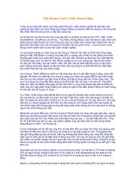
Figure 1-1 GSM worldwide (indicated by darker areas)
Because GSM provides a common standard, cellular subscribers
can use their telephones over the entire GSM service area which
includes all the countries around the world where the GSM
system is used.
In addition, GSM provides user services such as high speed data
communication, facsimile and a Short Message Service (SMS).
The GSM technical specifications are also designed to work
with other standards as it guarantees standard interfaces.
Finally, a key aspect of GSM is that the specifications are open-
ended and can be built upon to meet future requirements.
F Did you know?
7KHFRXQWULHVZLWKWKH
KLJKHVWQXPEHUVRI
*60VXEVFULEHUVDUH
WKH8QLWHG.LQJGRP
DQG,WDO\
1 Introduction to Mobile Telecommunications and GSM
EN/LZT 123 3321 R2A – 9 –
GSM SPECIFICATIONS
GSM was designed to be platform-independent. The GSM
specifications do not specify the actual hardware requirements,
but instead specify the network functions and interfaces in
detail. This allows hardware designers to be creative in how they
provide the actual functionality, but at the same time makes it
possible for operators to buy equipment from different suppliers.
The GSM recommendations consist of twelve series which are
listed in the table below These series were written by different
working parties and a number of expert groups. A permanent
nucleus was established in order to coordinate the working
parties and to manage the editing of the recommendations. All
these groups were organized by ETSI.
Series Content
01 General
02 Service aspects
03 Network aspects
04 MS - BSS interface and protocol
05 Physical layer on the radio path
06 Speech coding specification
07 Terminal adaptor for MS
08 BSS - MSC interface
09 Network interworking
10 Service interworking
11 Equipment and type approval specifications
12 Operation and maintenance
Table 1-5 GSM Recommendations
The GSM 1800 section is written as a delta part within the GSM
recommendations, describing only those differences between
GSM 900 and GSM 1800. GSM 1900 is based on GSM 1800
and has been adapted to meet the American National Standards
Institute (ANSI) standard.
GSM System Survey
– 10 – EN/LZT 123 3321 R2A
GSM PHASES
In the late 1980s, the groups involved in developing the GSM
standard realized that within the given time-frame they could not
complete the specifications for the entire range of GSM services
and features as originally planned. Because of this, it was
decided that GSM would be released in phases with phase 1
consisting of a limited set of services and features. Each new
phase builds on the services offered by existing phases.
Idea
Standardization
Implementation/usage
Phase 1
Phase 2
Phase 2+
1989 1990 1991 1992 1993 1994 1995
Figure 1-2 GSM phases
Phase 1
Phase 1 contains the most common services including:
• Voice telephony
• International roaming
• Basic fax/data services (up to 9.6 kbits/s)
• Call forwarding
• Call barring
• Short Message Service (SMS)
Phase 1 also incorporated features such as ciphering and
Subscriber Identity Module (SIM) cards. Phase 1 specifications
were then closed and cannot be modified.
1 Introduction to Mobile Telecommunications and GSM
EN/LZT 123 3321 R2A – 11 –
Phase 2
Additional features were introduced in GSM phase 2 including:
• Advice of charge
• Calling line identification
• Call waiting
• Call hold
• Conference calling
• Closed user groups
• Additional data communications capabilities
Phase 2+
The standardization groups have already begun to define the
next phase, 2+. The phase 2+ program will cover multiple
subscriber numbers and a variety of business oriented features.
Some of the enhancements offered by Phase 2+ include:
• Multiple service profiles
• Private numbering plans
• Access to Centrex services
• Internetworking with GSM 1800, GSM 1900 and the Digital
Enhanced Cordless Telecommunications (DECT) standard
Priorities and time schedules for new features and functions
depend primarily on the interest shown by operating companies
and manufacturers and technical developments in related areas.
GSM System Survey
– 12 – EN/LZT 123 3321 R2A
GSM NETWORK COMPONENTS
The GSM network is divided into two systems. Each of these
systems are comprised of a number of functional units which are
individual components of the mobile network. The two systems
are:
• Switching System (SS)
• Base Station System (BSS)
In addition, as with all telecommunications networks, GSM
networks are operated, maintained and managed from
computerized centers.
AUC
HLR EIR
SS
BSS
MSC
BTS
MS
NMC and OMC
Switching System
Signaling transmission
Call connections and
signaling transmission
Base Station System
Other
networks
BSC
GMSC
VLR
Figure 1-3 System model
1 Introduction to Mobile Telecommunications and GSM
EN/LZT 123 3321 R2A – 13 –
$EEUHYLDWLRQV
AUC AUthentication Center
BSC Base Station Controller
BTS Base Transceiver Station
EIR Equipment Identity Register
HLR Home Location Register
MS Mobile Station
MSC Mobile services Switching Center
NMC Network Management Center
OMC Operation and Maintenance Center
VLR Visitor Location Register
The SS is responsible for performing call processing and
subscriber related functions. It includes the following functional
units:
• Mobile services Switching Center (MSC)
• Home Location Register (HLR)
• Visitor Location Register (VLR)
• AUthentication Center (AUC)
• Equipment Identity Register (EIR)
The BSS performs all the radio-related functions. The BSS is
comprised of the following functional units:
• Base Station Controller (BSC)
• Base Transceiver Station (BTS)
The OMC performs all the operation and maintenance tasks for
the network such as monitoring network traffic and network
alarms. The OMC has access to both the SS and the BSS.
MSs do not belong to any of these systems.
GSM System Survey
– 14 – EN/LZT 123 3321 R2A
SWITCHING SYSTEM (SS) COMPONENTS
Mobile services Switching Center (MSC)
The MSC performs the telephony switching functions for the
mobile network. It controls calls to and from other telephony
and data systems, such as the Public Switched Telephone
Network (PSTN), Integrated Services Digital Network (ISDN),
public data networks, private networks and other mobile
networks.
Gateway Functionality
Gateway functionality enables an MSC to interrogate a
network’s HLR in order to route a call to a Mobile Station (MS).
Such an MSC is called a Gateway MSC (GMSC). For example,
if a person connected to the PSTN wants to make a call to a
GSM mobile subscriber, then the PSTN exchange will access
the GSM network by first connecting the call to a GMSC. The
same is true of a call from an MS to another MS.
Any MSC in the mobile network can function as a gateway by
integration of the appropriate software.
Home Location Register (HLR)
TheHLR is a centralized network database that stores and
manages all mobile subscriptions belonging to a specific
operator. It acts as a permanent store for a person’s subscription
information until that subscription is canceled. The information
stored includes:
• Subscriber identity
• Subscriber supplementary services
• Subscriber location information
• Subscriber authentication information
The HLR can be implemented in the same network node as the
MSC or as a stand-alone database. If the capacity of a HLR is
exceeded by the number of subscribers, additional HLRs may be
added.
1 Introduction to Mobile Telecommunications and GSM
EN/LZT 123 3321 R2A – 15 –
Visitor Location Register (VLR)
The VLR database contains information about all the mobile
subscribers currently located in an MSC service area. Thus,
there is one VLR for each MSC in a network. The VLR
temporarily stores subscription information so that the MSC can
service all the subscribers currently visiting that MSC service
area. The VLR can be regarded as a distributed HLR as it holds
a copy of the HLR information stored about the subscriber.
When a subscriber roams into a new MSC service area, the VLR
connected to that MSC requests information about the
subscriber from the subscriber’s HLR. The HLR sends a copy of
the information to the VLR and updates its own location
information. When the subscriber makes a call, the VLR will
already have the information required for call set-up.
AUthentication Center (AUC)
The main function of the AUC is to authenticate the subscribers
attempting to use a network. In this way, it is used to protect
network operators against fraud. The AUC is a database
connected to the HLR which provides it with the authentication
parameters and ciphering keys used to ensure network security.
Equipment Identity Register (EIR)
The EIR is a database containing mobile equipment identity
information which helps to block calls from stolen,
unauthorized, or defective MSs. It should be noted that due to
subscriber-equipment separation in GSM, the barring of MS
equipment does not result in automatic barring of a subscriber.
F Did you know?
$OWKRXJKXVHIXOWKH
(,5LVDFWXDOO\DQ
RSWLRQDOFRPSRQHQWR
I
D*60QHWZRUNDQG
LVWKHUHIRUHRIWHQQRW
XVHG
GSM System Survey
– 16 – EN/LZT 123 3321 R2A
BASE STATION SYSTEM (BSS) COMPONENTS
Base Station Controller (BSC)
The BSC manages all the radio-related functions of a GSM
network. It is a high capacity switch that provides functions such
as MS handover, radio channel assignment and the collection of
cell configuration data. A number of BSCs may be controlled by
each MSC.
Base Transceiver Station (BTS)
TheBTS controls the radio interface to the MS. The BTS
comprises the radio equipment such as transceivers and antennas
which are needed to serve each cell in the network. A group of
BTSs are controlled by a BSC.
NETWORK MONITORING CENTERS
Operation and Maintenance Center (OMC)
An OMC is a computerized monitoring center which is
connected to other network components such as MSCs and
BSCs via X.25 data network links. In the OMC, staff are
presented with information about the status of the network and
can monitor and control a variety of system parameters. There
may be one or several OMCs within a network depending on the
network size.
Network Management Center (NMC)
Centralized control of a network is done at a Network
Management Center (NMC). Only one NMC is required for a
network and this controls the subordinate OMCs. The advantage
of this hierarchical approach is that staff at the NMC can
concentrate on long term system-wide issues, whereas local
personnel at each OMC can concentrate on short term, regional
issues.
OMC and NMC functionality can be combined in the same
physical network node or implemented at different locations.
1 Introduction to Mobile Telecommunications and GSM
EN/LZT 123 3321 R2A – 17 –
MOBILE STATION (MS)
An MS is used by a mobile subscriber to communicate with the
mobile network. Several types of MSs exist, each allowing the
subscriber to make and receive calls. Manufacturers of MSs
offer a variety of designs and features to meet the needs of
different markets.
The range or coverage area of an MS depends on the output
power of the MS. Different types of MSs have different output
power capabilities and consequently different ranges. For
example, hand-held MSs have a lower output power and shorter
range than car-installed MSs with a roof mounted antenna.
Figure 1-4 Ranges for different types of MSs
GSM MSs consist of:
• A mobile terminal
• A Subscriber Identity Module (SIM)
Unlike other standards, in GSM the subscriber is separated from
the mobile terminal. Each subscriber’s information is stored as a
"smart card" SIM. The SIM can be plugged into any GSM
mobile terminal. This brings the advantages of security and
portability for subscribers. For example, subscriber A’s mobile
terminal may have been stolen. However, subscriber A’s own
SIM can be used in another person’s mobile terminal and the
calls will be charged to subscriber A.
GSM System Survey
– 18 – EN/LZT 123 3321 R2A
GSM GEOGRAPHICAL NETWORK STRUCTURE
Every telephone network needs a specific structure to route
incoming calls to the correct exchange and then on to the
subscriber. In a mobile network, this structure is very important
because the subscribers are mobile. As subscribers move
through the network, these structures are used to monitor their
location.
CELL
A cell is the basic unit of a cellular system and is defined as the
area of radio coverage given by one BS antenna system. Each
cell is assigned a unique number called Cell Global Identity
(CGI). In a complete network covering an entire country, the
number of cells can be quite high.
Cell
Figure 1-5 A cell
LOCATION AREA (LA)
A Location Area (LA) is defined as a group of cells. Within the
network, a subscriber’s location is known by the LA which they
are in. The identity of the LA in which an MS is currently
located is stored in the VLR.
When an MS crosses a boundary from a cell belonging to one
LA into a cell belonging to another LA, it must report its new
location to the network
1
. When an MS crosses a cell boundary
within an LA, it does need to report its new location to the
network. When there is call for an MS, a paging message is
broadcast within all cells belonging to an LA.
1
Note: This only occurs when the MS is idle. When the MS is on a call, it location is not updated, even if it changes
LAs.
1 Introduction to Mobile Telecommunications and GSM
EN/LZT 123 3321 R2A – 19 –
MSC SERVICE AREA
An MSC service area is made up of a number of LAs and
represents the geographical part of the network controlled by
one MSC. In order to be able to route a call to an MS, the
subscriber’s MSC service area is also recorded and monitored.
The subscriber’s MSC service area is stored in the HLR.
cell 6
cell 1
cell 5
cell 4
cell 2
cell 3
MSC
LA1
LA3
LA5
LA4
VLR
Figure 1-6 MSC service area
PLMN SERVICE AREA
A Public Land Mobile Network (PLMN) service area is the
entire set of cells served by one network operator and is defined
as the area in which an operator offers radio coverage and access
to its network. In any one country there may be several PLMN
service areas, one for each mobile operator’s network.
GSM System Survey
– 20 – EN/LZT 123 3321 R2A
GSM SERVICE AREA
The GSM service area is the entire geographical area in which a
subscriber can gain access to a GSM network. The GSM service
area increases as more operators sign contracts agreeing to work
together. Currently, the GSM service area spans dozens of
countries across the world from Ireland to Australia and South
Africa.
International roaming is the term applied when an MS moves
from one PLMN to another.
Figure 1-7 Relation between areas in GSM
1 Introduction to Mobile Telecommunications and GSM
EN/LZT 123 3321 R2A – 21 –
The figures below show alternative views of the same network:
• The first figure shows the network nodes and their layout
across the network. For simplicity, this may be referred to as
the hardware view of the network.
• The second figure shows the geographical network
configuration. For simplicity, this may be referred to as the
software view of the network.
HLR
EIR
AUC
GMSC
ILR
MSC/VLR 1
MSC/VLR 2
MSC Service Area 1
MSC Service Area 2
BSC 1B
BSC 1C
BSC 2B
BSC 1A
BSC 2A
PSTN
BSC 2C
LEGEND
MSC Boundary
BSC Boundary
PCM Links
Base Station
Figure 1-8 “Hardware” view of a sample network
HLR
EIR
AUC
GMSC
ILR
MSC/VLR 1
MSC/VLR 2
LA 1-B
LA 2-C
LA 2-A
LA 1-A
LA 2-D
PSTN
Cell 2-A-25
MSC Service Area 2
MSC Service Area 1
LEGEND
MSC Boundary
BSC Boundary
PCM Links
Base Station
LA 2-B
Figure 1-9 “Software” view of a sample network