Direct 3D Succinctly by Chris Rose
Bạn đang xem bản rút gọn của tài liệu. Xem và tải ngay bản đầy đủ của tài liệu tại đây (2.04 MB, 145 trang )
2
By
Chris Rose
Foreword by Daniel Jebaraj
3
Copyright © 2014 by Syncfusion Inc.
2501 Aerial Center Parkway
Suite 200
Morrisville, NC 27560
USA
All rights reserved.
mportant licensing information. Please read.
This book is available for free download from www.syncfusion.com on completion of a registration form.
If you obtained this book from any other source, please register and download a free copy from
www.syncfusion.com.
This book is licensed for reading only if obtained from www.syncfusion.com.
This book is licensed strictly for personal or educational use.
Redistribution in any form is prohibited.
The authors and copyright holders provide absolutely no warranty for any information provided.
The authors and copyright holders shall not be liable for any claim, damages, or any other liability arising
from, out of, or in connection with the information in this book.
Please do not use this book if the listed terms are unacceptable.
Use shall constitute acceptance of the terms listed.
SYNCFUSION, SUCCINCTLY, DELIVER INNOVATION WITH EASE, ESSENTIAL, and .NET ESSENTIALS are the
registered trademarks of Syncfusion, Inc.
Technical Reviewer: Jeff Boenig
Copy Editor: Ben Ball
Acquisitions Coordinator: Hillary Bowling, marketing coordinator, Syncfusion, Inc.
Proofreader: Darren West, content producer, Syncfusion, Inc.
I
4
Table of Contents
The Story behind the Succinctly Series of Books 7
About the Author 9
Chapter 1 Introduction 10
Chapter 2 Introduction to 3-D Graphics 11
Coordinate Systems 11
Model, World, and View Space 12
Colors 15
Graphics Pipeline 16
Render Targets, Swap Chain, and the Back Buffer 19
Depth Buffer 19
Device and Device Context 21
Chapter 3 Setting up the Visual Studio Template 22
Creating the Project 22
Changes to DirectXPage.xaml 23
Changes to App.XAML 27
Changes to SimpleTextRenderer 30
Chapter 4 Basic Direct3D 33
Clearing the Screen using Direct3D 33
Rendering a Triangle 34
Basic Model Class 34
Creating a Triangle 36
Creating a Constant Buffer 37
Vertex and Pixel Shaders 40
Rendering the Model 52
5
Chapter 5 Loading a Model 54
Object Model File Format 54
Adding a Model to the Project 55
OBJ File Syntax 60
Blender Export Settings 62
Model Class 63
Chapter 6 Texture Mapping 72
Texel or UV Coordinates 72
UV Layouts 73
Reading a Texture from a File 75
Applying the Texture2D 78
Chapter 7 HLSL Overview 88
Data Types 88
Scalar Types 88
Semantic Names 89
Vector Types 90
Accessing Vector Elements 91
Matrix Types 92
Accessing Matrix Elements 93
Matrix Swizzles 94
Other Data Types 94
Operators 95
Intrinsics 95
Short HLSL Intrinsic Reference 96
Chapter 8 Lighting 102
Normals 102
6
Reading Normals 103
Emissive Lighting 109
Ambient Lighting 110
Diffuse Lighting 110
Chapter 9 User Input 113
Control Types 113
Mouse Touchscreen Pointer 118
Chapter 10 Putting it all Together 123
Baddies and Bullets 123
GameObject Class 127
Background 131
Pixel Shader 133
SimpleTextRenderer 134
Chapter 11 Further Reading 144
7
The Story behind the Succinctly Series
of Books
Daniel Jebaraj, Vice President
Syncfusion, Inc.
taying on the cutting edge
As many of you may know, Syncfusion is a provider of software components for the
Microsoft platform. This puts us in the exciting but challenging position of always
being on the cutting edge.
Whenever platforms or tools are shipping out of Microsoft, which seems to be about every other
week these days, we have to educate ourselves, quickly.
Information is plentiful but harder to digest
In reality, this translates into a lot of book orders, blog searches, and Twitter scans.
While more information is becoming available on the Internet and more and more books are
being published, even on topics that are relatively new, one aspect that continues to inhibit us is
the inability to find concise technology overview books.
We are usually faced with two options: read several 500+ page books or scour the web for
relevant blog posts and other articles. Just as everyone else who has a job to do and customers
to serve, we find this quite frustrating.
The Succinctly series
This frustration translated into a deep desire to produce a series of concise technical books that
would be targeted at developers working on the Microsoft platform.
We firmly believe, given the background knowledge such developers have, that most topics can
be translated into books that are between 50 and 100 pages.
This is exactly what we resolved to accomplish with the Succinctly series. Isn’t everything
wonderful born out of a deep desire to change things for the better?
S
8
The best authors, the best content
Each author was carefully chosen from a pool of talented experts who shared our vision. The
book you now hold in your hands, and the others available in this series, are a result of the
authors’ tireless work. You will find original content that is guaranteed to get you up and running
in about the time it takes to drink a few cups of coffee.
Free forever
Syncfusion will be working to produce books on several topics. The books will always be free.
Any updates we publish will also be free.
Free? What is the catch?
There is no catch here. Syncfusion has a vested interest in this effort.
As a component vendor, our unique claim has always been that we offer deeper and broader
frameworks than anyone else on the market. Developer education greatly helps us market and
sell against competing vendors who promise to “enable AJAX support with one click,” or “turn
the moon to cheese!”
Let us know what you think
If you have any topics of interest, thoughts, or feedback, please feel free to send them to us at
We sincerely hope you enjoy reading this book and that it helps you better understand the topic
of study. Thank you for reading.
Please follow us on Twitter and “Like” us on Facebook to help us spread the
word about the Succinctly series!
9
About the Author
Chris Rose is an Australian software engineer. His background is mainly in data mining and
charting software for medical research. He has also developed desktop and mobile apps and a
series of programming videos for an educational channel on YouTube. He is a musician and
can often be found accompanying silent films at the Pomona Majestic Theatre in Queensland.
10
Chapter 1 Introduction
DirectX is an application programming interface (API) developed by Microsoft to enable
programmers to leverage the power of many different types of hardware with a uniform
programming interface. It contains components that deal with all aspects of multimedia including
graphics, sound, and input. In this book, we will look at techniques for programming three-
dimensional (3-D) graphics using DirectX 11 and Visual Studio 2012. The version of Visual
Studio used throughout the book is the Windows 8 version of Visual Studio Express 2012.
A background of C++ is assumed, and this book is designed as a follow up to the previous book
in the series (Direct2D Succinctly), which mostly looked at two-dimensional (2-D) graphics. We
will look at the basics of DirectX and 3-D graphics, communicating with the GPU and loading 3-
D model files. We will look at texture mapping, high-level shading language (HLSL), and
lighting. We will also look at how to read and respond to user input via a mouse, keyboard, and
touchscreen.
We will put it all together, including information on Direct2D from the previous book, and create
the beginnings of a simple 3-D game.
11
Chapter 2 Introduction to 3-D Graphics
Before we dive into DirectX, it is important to look at some of the terms and concepts behind 3-
D graphics. In this chapter, we will examine some fundamental concepts of 3-D graphics that
are applicable to all graphics APIs.
3-D graphics is an optical illusion, or a collection of techniques for creating optical illusions.
Colored pixels are lit up on a 2-D screen in such a way that the image on the screen resembles
objects with perspective. Nearer objects overlap and block those farther away, just as they
would in the real world.
Coordinate Systems
A coordinate system is a method for describing points in a geometric space. We will be using a
standard Cartesian coordinate system for our 3-D graphics. In 2-D graphics, points are specified
using two coordinates, one for each of the X and Y dimensions. The X coordinate usually
specifies the horizontal location of a point, and the Y coordinate specifies the vertical location of
a point. We will see later, when using 2-D textures, that it is also common to use the signifiers U
and V to describe 2-D texture coordinates.
In 3-D space, points are specified using three coordinates (X, Y, and Z). Any two coordinates
define a plane perpendicular to any other two. The positive and negative directions of each axis,
with respect to the monitor, can be arbitrarily chosen by placing a virtual camera in the 3-D
scene. For instance, the Y-axis can point upwards, the X-axis can point rightwards, and the Z-
axis can point into the screen. If you rotate the camera, the Y-axis can point out of the screen,
the X-axis can point downwards, and the Z-axis can point rightwards.
When working with a 3-D Cartesian coordinate system there is a choice to make as to which
direction each of the axes point with respect to one another. Any two axes define a 2-D plane.
For instance, the X- and Y-axes define a plane, and the Z- and X-axis define another. If you
imagine a camera oriented in such a way that the X- and Y-axes define a plane parallel to the
monitor, with the Y-axis pointing up and the X-axis pointing to the right, then there is a choice for
which direction the Z-axis points. It can point into or out of the screen. A commonly used
mnemonic for remembering these two coordinate systems is handedness, or right-handed
coordinates and left-handed coordinates. When you hold your hands in the same manner as
depicted in Figure 2.1, the fingers point in the positive directions of the axis.
12
Figure 1: Figure 2.1: Left-handed and Right-handed Coordinates
When using a left-handed coordinate system, the positive Z-axis points into the screen, the Y-
axis points up, and the X-axis points to the right. When using a right-handed coordinate system,
the positive Z-axis points out of the screen, the Y points up, and the X points to the right. We will
be using right-handed coordinates in the code, but DirectX is able to use either.
It is very important to know that the positive directions for the axes are only partially defined by
the handedness of the coordinates. The positive directions for the axes can point in any
direction with respect to the monitor, because the virtual camera or viewer is able to rotate
upside down, backwards, or any direction.
Model, World, and View Space
Models are usually created as separate assets using a 3-D modeling application. I have used
Blender for the examples in this book; Blender is available for download from
Models can be exported from the modeling application to files and
loaded into our programs. When the models are designed in the 3-D modeler, they are designed
with their own local origin. For instance, if you designed a table model, it might look like Figure
2.2 in the modeling application.
13
Figure 2: Figure 2.2: Table in the Blender Modeler
Figure 2.2 is a cropped screen shot of the Blender workspace. The red and green lines intersect
at the local origin for the object. In Blender, the red line is the X-axis and the green line is the Y-
axis. The Z-axis is not pictured, but it would point upwards and intersect the same point that the
X and Y intersect. The point where they meet is the location (0, 0, 0) in Blender's coordinates, it
is the origin in model coordinates. When we export the object to a file that we can read into our
application, the coordinates in the file will be specified with respect to the local origin.
Figure 2.3 shows another screen shot of the same model, but now it has been placed into a
room.
Figure 3: Figure 2.3: Table in World Space
14
Once we load a model file into our application, we can place the object at any position in our 3-
D world. It was modeled using its own local coordinates, but when we place it into the world, we
do so by specifying its position relative to the origin of the world coordinates. The origin of the
world coordinates can be seen in the image above. This is actually another screen shot from
Blender, and usually the axis will not be visible. The table has been placed in a simple room
with a floor, ceiling, and a few walls. This translation of the table's coordinates from its local
coordinates to the world is achieved in DirectX using a matrix multiplication. We multiply the
coordinates of the table by a matrix that positions the table in our 3-D world space. I will refer to
this matrix as the model matrix, since it is used to position individual models.
Once the objects are positioned relative to the world origin, the final step in representing the
world coordinate space is to place a camera or eye at some point in the virtual world. In 3-D
graphics, cameras are positioned and given a direction to face. The camera sees an area in the
virtual world that has a very particular shape. The shape is called a frustum. A frustum is the
portion of a geometric shape, usually a pyramid or cone that lies between two parallel planes
cutting the shape. The frustum in 3-D graphics is a square base pyramid shape with its apex at
the camera. The pyramid is cut at the near and far clipping planes (Figure 2.4).
Figure 4:
Figure 5: Figure 2.4: Frustum
Figure 2.4 depicts the viewing frustum. The camera is able to view objects within the yellow
shaded frustum, but it cannot see objects outside this area. Objects that are closer to the
camera than the blue shaded plane (called the near clipping plane) are not rendered, because
they are too close to the camera. Likewise, objects that are beyond the orange shaded plane
(called the far clipping plane) are also not rendered, because they are too far from the camera.
The camera moves around the 3-D world, and any objects that fall in the viewing frustum are
rendered. The objects that fall inside the viewing frustum are projected to the 2-D screen by
multiplying by another matrix that is commonly called the projection matrix.
Figure 2.5 shows a representation of projecting a 3-D shape onto a 2-D plane. In DirectX, the
actual process of projection is nothing more than a handful of matrix multiplications, but the
illustration may help to conceptualize the operation.
15
Figure 6: Figure 2.5: 3-D Projection
Figure 2.5 illustrates 3-D projection onto a 2-D plane. The viewer of the scene, depicted as a
camera, is on the left side of the image. The middle area, shaded in blue, is the projection
plane. It is a plane, which means it is 2-D and flat. It represents the area that the viewer can
see. On the far right side, we can see a 3-D cube. This is the object that the camera is looking
at. The cube on the right is meant to be a real 3-D object, and the cube projected onto the plane
is meant to be 2-D.
Colors
Each pixel on a monitor or screen has three tiny lights very close together. Every pixel has a
red, green, and blue light, one beside the other. Each of these three lights can shine at different
levels of intensity, and our eyes see a mixture of these three intensities as the pixel’s color.
Humans see colors as a mixture of three primary colors: red, green, and blue.
Colors are described in Direct3D using normalized RGB or RGBA components. Each pixel has
a red, green, and blue variable that specifies the intensity of each of the three primary colors.
The components are normalized, so they should range from 0.0f to 1.0f inclusive. 0.0f means
0% of a particular component and 1.0f means 100%.
Colors are specified using three (RGB) or four (RGBA) floating point values with the red first,
green second, and blue third. If there is an alpha component, it is last.
To create a red color with 100% red, 13% green and 25% blue, we can use (1.0f, 0.13f,
0.25f).
16
If present, the alpha component is normally used for transparency. In this book, we will not be
using the alpha channel, and its value is irrelevant, but I will set it to 100% or 1.0f.
Graphics Pipeline
The graphics pipeline is a set of steps that take some representation of objects, usually a
collection of 3-D coordinates, colors, and textures, and transform them into pixels to be
displayed on the screen. Every graphics API has its own pipeline. For instance, the OpenGL
pipeline is quite different from the DirectX graphics pipeline. The pipelines are always being
updated, and new features are added with each new generation of the DirectX API.
In early versions of DirectX, the pipeline was fixed, and it was a predesigned set of stages that
the programmers of the API designed. Programmers could select several options that altered
the way the GPU rendered the final graphics, but the entire process was largely set in stone.
Today's graphics pipeline is extremely flexible and it features many stages that are directly
programmable. This means that the pipeline is vastly more complex, but it is also much more
flexible. Figure 2.6 is a general outline of the stages of the current DirectX 11 graphics pipeline.
17
Figure 7: Figure 2.6: DirectX 11 Graphics Pipeline
The rectangular boxes in Figure 2.6 indicate stages that are necessary, and the ellipses indicate
the stages that are optional. Purple stages are programmable using the HLSL language and
blue boxes are fixed or nonprogrammable stages. The black arrows indicate the execution flow
of the pipeline. For instance, the domain shader leads to the geometry shader, and the vertex
shader has three possible subsequent stages. Following the vertex shader can be the hull
shader, the geometry shader, or the pixel shader.
Each pipeline stage is designed to allow some specific functionality. In this book, we will
concentrate on the two most important stages: the vertex shader stage and the pixel shader
stage. The following is a general description of all the stages.
Input Assembler:
This stage of the pipeline reads data from the GPU's buffers and passes it to the vertex shader.
It assembles the input for the vertex shader based on descriptions of the data and its layout.
Vertex Shader:
This stage processes vertices. It can lead to the hull, geometry, or pixel shader, depending on
what the programmer needs to do. We will examine this stage in detail in later chapters. The
vertex shader is a required stage, and it is also completely programmable using the HLSL
language in DirectX.
18
Hull Shader:
This stage and the next two are all used for tessellation, and they are optional. Tessellation can
be used to approximate complex shapes from simpler ones. The Hull shader creates geometry
patches or control points for the tessellator stage.
Tessellator:
The tessellator takes the geometry patches from the hull shader and divides the primitives into
smaller sections.
Domain Shader:
The domain shader takes the output from the tessellator and generates vertices from it.
Geometry Shader:
The geometry shader is a programmable part of the pipeline that works with entire primitives.
These could be triangles, points, or lines. The geometry shader stage can follow the vertex
shader if you are not using tessellation.
Rasterizer:
The rasterizer takes the output from the previous stages, which consists of vertices, and
decides which are visible and which should be passed onto the pixel shaders. Any pixels that
are not visible do not need to be processed by the subsequent pixel shader stage. A nonvisible
pixel could be outside the screen or located on the back faces of objects that are not facing the
camera.
Pixel Shader:
The pixel shader is another programmable part of the pipeline. It is executed once for every
visible pixel in a scene. This stage is required, and we will examine pixel shaders in more detail
in later chapters.
Output Merger:
This stage takes the output from the other stages and creates the final graphics.
19
Render Targets, Swap Chain, and the Back Buffer
The GPU writes pixel data to an array in its memory that is sent to the monitor for display. The
memory buffer that the GPU writes pixels to is called a render target. There are usually two or
more buffers; one is being shown on the screen, while the GPU writes the next frame to another
that cannot be seen. The buffer the user can see is called the front buffer. The render target to
which the GPU writes is called the back buffer. When the GPU has finished rendering a frame to
the back buffer, the buffers swap. The back buffer becomes the front buffer and is displayed on
the screen, and the front buffer becomes the back buffer. The GPU renders the next frame to
the new back buffer, which was previously the front buffer. This repeated writing of data to the
back buffer and swapping of buffers enables smooth graphics. These buffers are all 2-D arrays
of RGB pixel data.
The buffers are rendered and swapped many times in sequence by an object called the swap
chain. It is called a swap chain because there need not be only two buffers; there could be a
chain of many buffers each rendered to and flipped to the screen in sequence.
Depth Buffer
When the GPU renders many objects, it must render those closer to the viewer and not the
objects behind or obscured by these closer objects. It may seem that, if there are two objects
one in front of the other, the viewer will see the front object and the hidden object does not
need to be rendered. In graphics programming, the vertices and pixels are all rendered
independently of each other using shaders. The GPU does not know when it is rendering a
vertex if this particular vertex is in front of or behind all the other vertices in the scene.
We use a z-buffer to solve this problem. A z-buffer is a 2-D array usually consisting of floating
point values. The values indicate the distance to the viewer from each of the pixels currently
rasterized in the rasterizer stage of the pipeline. When the GPU renders a pixel from an object
at some distance (Z) from the viewer, it first checks that the Z of the current pixel is closer than
the Z that it previously rendered. If the pixel has already been rendered and the object was
closer last time, the new pixel does not need to be rendered; otherwise the pixel should be
updated.
20
Figure 8: Figure 2.7: Depth Buffer and Faces
Figure 2.7 illustrates two examples of a box being rasterized, or turned into pixels. There is a
camera looking at the box on the left. In this example, we will step through rasterizing two faces
of the boxes: the one nearest the camera and the one farthest away. In reality, a box has six
faces, and this process should be easy to extrapolate to the remaining faces.
Imagine that, in example A, the first face of the box that is rasterized is described by the corners
marked 1, 2, 3, and 4. This is the face nearest to the camera. The GPU will rasterize all the
points on this face. It will record the distance from each point to the camera in the depth buffer
as it writes the rasterized pixels to a pixel buffer.
Eventually, the farthest face from the camera will also be read. This face is described by the
corners 5, 6, 7, and 8. Corner 8 is not visible in the diagram. Once again, the GPU will look at
the points that comprise the face, and determine how far each is from the camera. It will look to
the depth buffer and note that these points have already been rasterized. The distance that it
previously recorded in the depth buffer is nearer to the camera than those from the far face. The
points from the far face cannot be seen by the camera, because they are blocked by the front
face. The pixels written while rasterizing the front face will not be overwritten.
Contrast this with example B on the right-hand side of Figure 2.7. Imagine that the face that is
rasterized first is the one described by corners 1, 2, 3, and 4. Corner 4 is not depicted in the
diagram. This time, it is the far face from the camera that is rasterized first. The GPU will
determine the distance from each point on this face to the camera. It will write these distances
to the depth buffer while writing the rasterized pixels to a pixel buffer. After a while, it will come
to the nearer face, described by corners 5, 6, 7, and 8. The GPU will calculate the distance of
each of the points on the face, and it will compare this with the distance it wrote to the depth
buffer. It will note that the present points, those comprising the nearer face, are closer to the
camera than the ones it rasterized before. It will therefore overwrite the previously rasterized
pixels with the new ones and record the nearer depths in the depth buffer.
21
The above description is a simplified version of the use of depth buffers in the rasterizer stage of
the pipeline. As you can imagine, it is easy to rasterize a simple box in this manner, but usually
3-D scenes are composed of thousands or millions of faces, not two as in the previous example.
Extensive and ongoing research is constantly finding new ways to improve operations like this,
and reduce the number of reads and writes to the depth and pixel buffers. In DirectX, the faces
farthest from the camera in the diagrams will actually be ignored by the GPU, simply because
they are facing away from the camera. They are back faces and will be culled in the process
called back face culling.
Device and Device Context
Device and device context are both software abstractions of the graphics card or Direct3D
capable hardware in the machine. They are both classes with many important methods for
creating and using resources on the GPU. The device tends to be lower level than the device
context. The device creates the context and many other resources. The device context is
responsible for rendering the scene, and creating and managing resources that are higher level
than the device.
22
Chapter 3 Setting up the Visual Studio
Template
The code in this book is based on the Direct2D App (XAML) template. Most of the functionality
of this template should be removed before we begin, and I will spend some time explaining what
to remove to get a basic Direct2D/Direct3D framework from this template. The code changes in
this chapter are designed to create the starting point for any Direct2D or Direct3D application.
Creating the Project
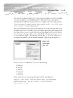
Open Visual Studio 2012 and create a new Direct2D App (XAML) project. I have named my
project DXGameProgramming in the screen shot (Figure 3.1). Keep in mind that if you use a
different name for your project you should rename all the references to the DXGameProgramming
namespace in your code.
Figure 9: Figure 3.1: Starting a new Direct2D App (XAML) project
Note: I have based all of the code throughout this book on the Direct2D App
(XAML) template. This template sets up an application to use both 2-D and 3-
D. We will be concentrating mainly on Direct3D, but Direct2D is also very
important in creating 3-D applications. Direct2D is used to render things like
the heads up display (HUD), player scores, various other sprites, and
possibly the backgrounds.
23
Changes to DirectXPage.xaml
The main XAML page for the application has some controls that we do not need, and these can
be removed. Double-click the DirectXPage.XAML file in the solution explorer. This should open
the page in Visual Studio’s XAML page designer. Delete the text control that says “Hello, XAML”
by right-clicking the object and selecting Delete from the context menu (see Figure 3.2).
Figure 10: Figure 3.2: Deleting Hello, XAML
Select the XAML code for the Page.BottomAppBar and delete it. The code for the
DirectXPage.xaml file is presented below. The following code table shows the XAML code after
the Page.BottomAppBar has been removed.
<Page
x:Class="DXGameProgramming.DirectXPage"
xmlns="
xmlns:x="
xmlns:local="using:DXGameProgramming"
xmlns:d="
xmlns:mc=" />compatibility/2006"
mc:Ignorable="d">
<SwapChainBackgroundPanel x:Name="SwapChainPanel"
PointerMoved="OnPointerMoved" PointerReleased="OnPointerReleased"/>
</Page>
24
The DirectXPage.xaml.cpp contains functionality to change the background color and move
some text around the screen; this can all be removed. There are several changes to the
DirectXPage.xaml.cpp to make. For convenience, the entire modified code is presented in the
following code table. In the listing, the four methods OnPreviousColorPressed,
OnNextColorPressed, SaveInternalState and LoadInternalState have been removed. All
of the lines that reference the m_renderNeeded variable, the m_lastPointValid bool, and the
m_lastPoint point have also been removed. These variables are used to prevent rendering
until the user interacts with the application. This is not useful for a real-time game, since the
nonplayer characters and physics of a real-time game continue even when the player does
nothing. These changes will make our application update at 60 frames per second, instead of
waiting for the user to move the pointer. I have also removed the code in the OnPointerMoved
event. After making these changes, the project will not compile, since we removed methods that
are referenced in other files.
//
// DirectXPage.xaml.cpp
// Implementation of the DirectXPage.xaml class.
//
#include "pch.h"
#include "DirectXPage.xaml.h"
using namespace DXGameProgramming;
using namespace Platform;
using namespace Windows::Foundation;
using namespace Windows::Foundation::Collections;
using namespace Windows::Graphics::Display;
using namespace Windows::UI::Input;
using namespace Windows::UI::Core;
using namespace Windows::UI::Xaml;
using namespace Windows::UI::Xaml::Controls;
using namespace Windows::UI::Xaml::Controls::Primitives;
using namespace Windows::UI::Xaml::Data;
using namespace Windows::UI::Xaml::Input;
using namespace Windows::UI::Xaml::Media;
using namespace Windows::UI::Xaml::Navigation;
DirectXPage::DirectXPage()
{
InitializeComponent();
m_renderer = ref new SimpleTextRenderer();
m_renderer->Initialize(
25
Window::Current->CoreWindow,
SwapChainPanel,
DisplayProperties::LogicalDpi
);
Window::Current->CoreWindow->SizeChanged +=
ref new TypedEventHandler<CoreWindow^,
WindowSizeChangedEventArgs^>(this, &DirectXPage::OnWindowSizeChanged);
DisplayProperties::LogicalDpiChanged +=
ref new DisplayPropertiesEventHandler(this,
&DirectXPage::OnLogicalDpiChanged);
DisplayProperties::OrientationChanged +=
ref new DisplayPropertiesEventHandler(this,
&DirectXPage::OnOrientationChanged);
DisplayProperties::DisplayContentsInvalidated +=
ref new DisplayPropertiesEventHandler(this,
&DirectXPage::OnDisplayContentsInvalidated);
m_eventToken = CompositionTarget::Rendering::add(ref new
EventHandler<Object^>(this, &DirectXPage::OnRendering));
m_timer = ref new BasicTimer();
}
void DirectXPage::OnPointerMoved(Object^ sender,
PointerRoutedEventArgs^ args)
{
}
void DirectXPage::OnPointerReleased(Object^ sender,
PointerRoutedEventArgs^ args)
{
}
void DirectXPage::OnWindowSizeChanged(CoreWindow^ sender,
WindowSizeChangedEventArgs^ args)
{
m_renderer->UpdateForWindowSizeChange();
}