Mechanical Science HandbooksMechanical Science Handbooks 20000 Part 9 pps
Bạn đang xem bản rút gọn của tài liệu. Xem và tải ngay bản đầy đủ của tài liệu tại đây (355.88 KB, 13 trang )
Miscellaneous Mechanical Components DOE-HDBK-1018/2-93 COOLING TOWERS
Summary
The important information in this chapter is summarized below.
Cooling Towers S ummary
The cooling tower removes heat from water used in cooling systems within
the plant. The heat is released to the air rather than to a lake or stream.
This allows facilities to locate in areas with less water available because
the cooled water can be recycled. It also aids environmental efforts by not
contributing to thermal pollution.
Induced draft cooling towers use fans to create a draft that pulls air
through the cooling tower fill. Because the water to be cooled is
distributed such that it cascades over the baffles, the air blows through the
water, cooling it.
Forced draft cooling towers blow air in at the bottom of the tower. The
air exits at the top of the tower. Water distribution and recirculation
difficulties limit their use.
Natural convection cooling towers function on the basic principle that hot
air rises. As the air inside the tower is heated, it rises through the tower.
This process draws more air in, creating a natural air flow to provide
cooling of the water.
Rev. 0 ME-05
Page 23
DEMINERALIZERS DOE-HDBK-1018/2-93 Miscellaneous Mechanical Components
DEMINERALIZERS
The cost of corrosion and radioactive contamination caused by poor water quality
in nuclear facilities is enormous. Demineralizers are an intricate part of water
quality control. The chemical theory of demineralizers is detailed in the
Chemistry Fundamentals Handbook. This chapter will address the mechanics of
how demineralizers operate.
EO 1.11 STATE the purpose of a demineralizer.
Purpose of Demineralizers
Dissolved impurities in power plant fluid systems generate corrosion problems and decrease
efficiency due to fouled heat transfer surfaces. Demineralization of the water is one of the most
practical and common methods available to remove these dissolved impurities.
In the plant, demineralizers (also called ion-exchangers) are used to hold ion exchange resins and
transport water through them. Ion exchangers are generally classified into two groups: single-
bed ion exchangers and mixed-bed ion exchangers.
Demineralizers
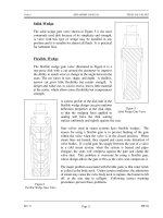
A demineralizer is basically a cylindrical tank with connections at the top for water inlet and
resin addition, and connections at the bottom for the water outlet. The resin can usually be
changed through a connection at the bottom of the tank. The resin beads are kept in the
demineralizer by upper and lower retention elements, which are strainers with a mesh size
smaller then the resin beads. The water to be purified enters the top at a set flow rate and flows
down through the resin beads, where the flow path causes a physical filter effect as well as a
chemical ion exchange.
Single-Bed Demineralizers
A single-bed demineralizer contains either cation or anion resin beads. In most cases, there are
two, single-bed ion exchangers in series; the first is a cation bed and the second is an anion bed.
Impurities in plant water are replaced with hydrogen ions in the cation bed and hydroxyl ions
in the anion bed. The hydrogen ions and the hydroxyl ions then combine to form pure water.
The Chemistry Handbook, Module 4, Principles of Water Treatment, addresses the chemistry of
demineralizers in more detail.
ME-05 Rev. 0
Page 24
Miscellaneous Mechanical Components DOE-HDBK-1018/2-93 DEMINERALIZERS
Figure 13 illustrates a single-bed demineralizer. When in use, water flows in through the inlet
to a distributor at the top of the tank. The water flows down through the resin bed and exits out
through the outlet. A support screen at the bottom prevents the resin from being forced out of
the demineralizer tank.
Single-Bed Regeneration
Figure 13 Single-Bed Demineralizer
The regeneration of a single-bed ion exchanger is a three-step process. The first step is a
backwash, in which water is pumped into the bottom of the ion exchanger and up through the
resin. This fluffs the resin and washes out any entrained particles. The backwash water goes
out through the normal inlet distributor piping at the top of the tank, but the valves are set to
direct the stream to a drain so that the backwashed particles can be pumped to a container for
waste disposal.
The second step is the actual regeneration step, which uses an acid solution for cation units and
caustic solution for anion units. The concentrated acid or caustic is diluted to approximately
10% with water by opening the dilution water valve, and is then introduced through a
distribution system immediately above the resin bed. The regenerating solution flows through
the resin and out the bottom of the tank to the waste drain.
The final step is a rinsing process, which removes any excess regenerating solution. Water is
pumped into the top of the tank, flows down through the resin bed and out at the bottom drain.
Rev. 0 ME-05
Page 25
DEMINERALIZERS DOE-HDBK-1018/2-93 Miscellaneous Mechanical Components
To return the ion exchanger to service, the drain valve is closed, the outlet valve is opened, and
the ion exchanger is ready for service.
Single-bed demineralizers are usually regenerated "in place." The resins are not pumped out to
another location for regeneration. The regeneration process is the same for cation beds and for
anion beds; only the regenerating solution is different. It is important to realize that if the ion
exchanger has been exposed to radioactive materials, the backwash, regeneration, and rinse
solutions may be highly radioactive and must be treated as a radioactive waste.
Mixed-Bed Demineralizer
A mixed-bed demineralizer is a demineralizer in which the cation and anion resin beads are
mixed together. In effect, it is equivalent to a number of two-step demineralizers in series. In
a mixed-bed demineralizer, more impurities are replaced by hydrogen and hydroxyl ions, and
the water that is produced is extremely pure. The conductivity of this water can often be less
than 0.06 micromhos per centimeter.
Mixed-Bed Regeneration
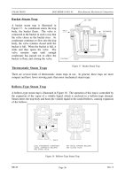
The mixed-bed demineralizer shown in Figure 14 is designed to be regenerated in place, but the
process is more complicated than the regeneration of a single-bed ion exchanger. The steps in
the regeneration are shown in Figure 14.
Figure 14a shows the mixed-bed ion exchanger in the operating, or on-line mode. Water enters
through a distribution header at the top and exits through the line at the bottom of the vessel.
Regeneration causes the effluent water to increase in electrical conductivity.
The first regeneration step is backwash, as shown in Figure 14b. As in a single-bed unit,
backwash water enters the vessel at the bottom and exits through the top to a drain. In addition
to washing out entrained particles, the backwash water in a mixed-bed unit must also separate
the resins into cation and anion beds. The anion resin has a lower specific gravity than the
cation resin; therefore, as the water flows through the bed, the lighter anion resin beads float
upward to the top. Thus, the mixed-bed becomes a split bed. The separation line between the
anion bed at the top and the cation bed at the bottom is called the resin interface. Some resins
can be separated only when they are in the depleted state; other resins separate in either the
depleted form or the regenerated form.
The actual regeneration step is shown in Figure 14c. Dilution water is mixed with caustic
solution and introduced at the top of the vessel, just above the anion bed. At the same time,
dilution water is mixed with acid and introduced at the bottom of the vessel, below the cation
bed. The flow rate of the caustic solution down to the resin interface is the same as the flow rate
of the acid solution up to the resin interface. Both solutions are removed at the interface and
dumped to a drain.
ME-05 Rev. 0
Page 26
Miscellaneous Mechanical Components DOE-HDBK-1018/2-93 DEMINERALIZERS
Figure 14 Regeneration of a Mixed-Bed Demineralizer
Rev. 0 ME-05
Page 27
DEMINERALIZERS DOE-HDBK-1018/2-93 Miscellaneous Mechanical Components
During the regeneration step, it is important to maintain the cation and anion resins at their
proper volume. If this is not done, the resin interface will not occur at the proper place in the
vessel, and some resin will be exposed to the wrong regenerating solution. It is also important
to realize that if the ion exchanger has been involved with radioactive materials, both the
backwash and the regenerating solutions may be highly radioactive and must be treated as liquid
radioactive waste.
The next step is the slow rinse step, shown in Figure 14d, in which the flow of dilution water
is continued, but the caustic and acid supplies are cut off. During this two-direction rinse, the
last of the regenerating solutions are flushed out of the two beds and into the interface drain.
Rinsing from two directions at equal flow rates keeps the caustic solution from flowing down
into the cation resin and depleting it.
In the vent and partial drain step, illustrated in Figure 14e, the drain valve is opened, and some
of the water is drained out of the vessel so that there will be space for the air that is needed to
re-mix the resins. In the air mix step, (Figure 14f) air is usually supplied by a blower, which
forces air in through the line entering the bottom of the ion exchanger. The air mixes the resin
beads and then leaves through the vent in the top of the vessel. When the resin is mixed, it is
dropped into position by slowly draining the water out of the interface drain while the air mix
continues.
In the final rinse step, shown in Figure 14g, the air is turned off and the vessel is refilled with
water that is pumped in through the top. The resin is rinsed by running water through the vessel
from top to bottom and out the drain, until a low conductivity reading indicates that the ion
exchanger is ready to return to service.
External Regeneration
Some mixed-bed demineralizers are designed to be regenerated externally, with the resins being
removed from the vessel, regenerated, and then replaced. With this type of demineralizer, the
first step is to sluice the mixed bed with water (sometimes assisted by air pressure) to a cation
tank in a regeneration facility. The resins are backwashed in this tank to remove suspended
solids and to separate the resins. The anion resins are then sluiced to an anion tank. The two
batches of separated resins are regenerated by the same techniques used for single-bed ion
exchangers. They are then sluiced into a holding tank where air is used to remix them. The
mixed, regenerated, resins are then sluiced back to the demineralizer.
External regeneration is typically used for groups of condensate demineralizers. Having one
central regeneration facility reduces the complexity and cost of installing several demineralizers.
External regeneration also allows keeping a spare bed of resins in a holding tank. Then, when
a demineralizer needs to be regenerated, it is out of service only for the time required to sluice
out the depleted bed and sluice a fresh bed in from the holding tank. A central regeneration
facility may also include an ultrasonic cleaner that can remove the tightly adherent coating of
dirt or iron oxide that often forms on resin beads. This ultrasonic cleaning reduces the need for
chemical regeneration.
ME-05 Rev. 0
Page 28
Miscellaneous Mechanical Components DOE-HDBK-1018/2-93 DEMINERALIZERS
Summary
The important information in this chapter is summarized below.
Demineralizers Summary
Demineralization of water is one of the most practical and common
methods used to remove dissolved contaminates. Dissolved impurities
in power plant fluid systems can generate corrosion problems and
decrease efficiency due to fouled heat transfer surfaces. Demineralizers
(also called ion-exchangers) are used to hold ion exchange resins and
transport water through them. Ion exchangers are generally classified
into two groups: single-bed ion exchangers and mixed-bed ion
exchangers.
A demineralizer is basically a cylindrical tank with connections at the
top for water inlet and resin addition, and connections at the bottom for
the water outlet. The resin can usually be changed out through a
connection at the bottom of the tank. The resin beads are kept in the
demineralizer by upper and lower retention elements, which are strainers
with a mesh size smaller then the resin beads.
The water to be purified enters the top at a set flow rate, flows down
through the resin beads where the flow path causes a physical filter
effect as well as a chemical ion exchange. The chemistry of the resin
exchange is explained in detail in the Chemistry Fundamentals
Handbook.
There are two types of demineralizers, single-bed and mixed-bed.
Single-bed demineralizers have resin of either cation or anion exchange
sites. Mixed-bed demineralizers contain both anion and cation resin.
All demineralizers will eventually be exhausted from use. To
regenerate the resin and increase the demineralizer's efficiency, the
demineralizers are regenerated. The regeneration process is slightly
different for a mixed-bed demineralizer compared to the single-bed
demineralizer. Both methods were explained in this chapter.
Rev. 0 ME-05
Page 29
PRESSURIZERS DOE-HDBK-1018/2-93 Miscellaneous Mechanical Components
PRESSURIZERS
Pressurizers are used for reactor system pressure control. The pressurizer is the
component that allows a water system, such as the reactor coolant system in a
PWR facility, to maintain high temperatures without boiling. The function of
pressurizers is discussed in this chapter.
EO 1.12 STATE the four purposes of a pressurizer.
EO 1.13 DEFINE the following terms attributable to a dynamic
pressurizer system:
a. Spray nozzle c. Outsurge
b. Insurge d. Surge volume
Introduction
There are two types of pressurizers: static and dynamic. A static pressurizer is a partially filled
tank with a required amount of gas pressure trapped in the void area. A dynamic pressurizer
is a tank in which its saturated environment is controlled through use of heaters (to control
temperature) and sprays (to control pressure).
This chapter focuses on the dynamic pressurizer. A dynamic pressurizer utilizes a controlled
pressure containment to keep high temperature fluids from boiling, even when the system
undergoes abnormal fluctuations.
Before discussing the purpose, construction, and operation of a pressurizer, some preliminary
information about fluids will prove helpful.
The evaporation process is one in which a liquid is converted into a vapor at temperatures below
the boiling point. All the molecules in the liquid are continuously in motion. The molecules
that move most quickly possess the greatest amount of energy. This energy occasionally escapes
from the surface of the liquid and moves into the atmosphere. When molecules move into the
atmosphere, the molecules are in the gaseous, or vapor, state.
Liquids at a high temperature have more molecules escaping to the vapor state, because the
molecules can escape only at higher speeds. If the liquid is in a closed container, the space
above the liquid becomes saturated with vapor molecules, although some of the molecules return
to the liquid state as they slow down. The return of a vapor to a liquid state is called
condensation. When the amount of molecules that condense is equal to the amount of molecules
that evaporate, there is a dynamic equilibrium between the liquid and the vapor.
ME-05 Rev. 0
Page 30
Miscellaneous Mechanical Components DOE-HDBK-1018/2-93 PRESSURIZERS
Pressure exerted on the surface of a liquid by a vapor is called vapor pressure. Vapor pressure
increases with the temperature of the liquid until it reaches saturation pressure, at which time
the liquid boils. When a liquid evaporates, it loses its most energetic molecules, and the average
energy per molecule in the system is lowered. This causes a reduction in the temperature of the
liquid.
Boiling is the activity observed in a liquid when it changes from the liquid phase to the vapor
phase through the addition of heat. The term saturated liquid is used for a liquid that exists at
its boiling point. Water at 212
o
F and standard atmospheric pressure is an example of a saturated
liquid.
Saturated steam is steam at the same temperature and pressure as the water from which it was
formed. It is water, in the form of a saturated liquid, to which the latent heat of vaporization
has been added. When heat is added to a saturated steam that is not in contact with liquid, its
temperature is increased and the steam is superheated. The temperature of superheated steam,
expressed as degrees above saturation, is called degrees of superheat.
General Description
The pressurizer provides a point in the reactor system where liquid and vapor can be maintained
in equilibrium under saturated conditions, for control purposes. Although designs differ from
facility to facility, a typical pressurizer is designed for a maximum of about 2500 psi and 680°F.
Dynamic Pressurizers
A dynamic pressurizer serves to:
maintain a system's pressure above its saturation point,
provide a means of controlling system fluid expansion and contraction,
provide a means of controlling a system's pressure, and
provide a means of removing dissolved gasses from the system by venting the
vapor space of the pressurizer.
Construction
A dynamic pressurizer is constructed from a tank equipped with a heat source such as electric
heaters at its base, a source of cool water, and a spray nozzle. A spray nozzle is a device
located in the top of the pressurizer that is used to atomize the incoming water.
Rev. 0 ME-05
Page 31
PRESSURIZERS DOE-HDBK-1018/2-93 Miscellaneous Mechanical Components
A dynamic pressurizer must be connected in the system to allow a differential pressure to exist
across it. The bottom connection, also called the surge line, is the lower of the two pressure
lines. The top connection, referred to as the spray line, is the higher pressure line. Differential
pressure is obtained by connecting the pressurizer to the suction and discharge sides of the pump
servicing the particular system. Specifically, the surge (bottom connection) is connected to the
pump's suction side; the spray line (top connection) is connected to the pump's discharge side.
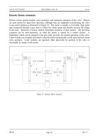
A basic pressurizer is illustrated in Figure 15.
The hemispherical top and bottom
Figure 15 Basic Pressurizer
heads are usually constructed of
carbon steel, with austenitic stainless
steel cladding on all surfaces exposed
to the reactor system water.
The pressurizer can be activated in
two ways. Partially filling the
pressurizer with system water is the
first. After the water reaches a
predetermined level, the heaters are
engaged to increase water
temperature. When the water reaches
saturation temperature, it begins to
boil. Boiling water fills the void
above the water level, creating a
saturated environment of water and
steam. The other method involves
filling the pressurizer completely,
heating the water to the desired
temperature, then partially draining
the water and steam mixture to create
a steam void at the top of the vessel.
Water temperature determines the
amount of pressure developed in the
steam space, and the greater the
amount of time the heaters are
engaged, the hotter the environment
becomes. The hotter the
environment, the greater the amount
of pressure.
Installing a control valve in the spray
line makes it possible to admit cooler water from the top of the pressurizer through the spray
nozzle. Adding cooler water condenses the steam bubble, lowers the existing water temperature,
and reduces the amount of system pressure.
ME-05 Rev. 0
Page 32
Miscellaneous Mechanical Components DOE-HDBK-1018/2-93 PRESSURIZERS
Operation
The level of water within a pressurizer is directly dependant upon the temperature, and thus the
density, of the water in the system to which the pressurizer is connected. An increase in system
temperature causes the density of the water to decrease. This decreased density causes the water
to expand, causing the level of water to increase in the vessel. The increased level of water in
a pressurizer is referred to as an insurge. An insurge compresses the vapor space, which in turn
causes the system pressure to rise. This results in slightly superheated steam in contact with the
subcooled pressurizer liquid. The superheated steam transfers heat to the liquid and to the
pressurizer walls. This re-establishes and maintains the saturated condition.
A decrease in system temperature causes the density to increase which causes the system water
volume to contract. The contraction (drop) in pressurizer water level and increase in vapor space
is referred to as an outsurge. The increase in vapor space causes the pressure to drop, flashing
the heated water volume and creating more steam. The increased amount of steam re-establishes
the saturated state. Flashing continues until the decrease in water level ceases and saturated
conditions are restored at a somewhat lower pressure.
In each case, the final conditions place the pressurizer level at a new value. The system pressure
remains at approximately its previous value, with relatively small pressure variations during the
level change, provided that the level changes are not too extreme.
In actual application, relying on saturation to handle all variations in pressure is not practical.
In conditions where the system water is surging into the pressurizer faster than the pressurizer
can accommodate for example, additional control is obtained by activating the spray. This spray
causes the steam to condense more rapidly, thereby controlling the magnitude of the pressure
rise.
When a large outsurge occurs, the level can drop rapidly and the water cannot flash to steam fast
enough. This results in a pressure drop. The installed heaters add energy to the water and cause
it to flash to steam faster, thereby reducing the pressure drop. The heaters can also be left on
to re-establish the original saturation temperature and pressure. In certain designs, pressurizer
heaters are energized continuously to make up for heat losses to the environment.
The pressurizer's heater and spray capabilities are designed to compensate for the expected surge
volume. The surge volume is the volume that accommodates the expansion and contraction of
the system, and is designed to be typical of normal pressurizer performance. Plant transients may
result in larger than normal insurges and outsurges. When the surge volume is exceeded, the
pressurizer may fail to maintain pressure within normal operating pressures.
Rev. 0 ME-05
Page 33
PRESSURIZERS DOE-HDBK-1018/2-93 Miscellaneous Mechanical Components
Pressurizer operation, including spray and heater operation, is usually automatically controlled.
Monitoring is required in the event the control features fail, because the effect on the system
could be disastrous without operator action.
Summary
The important information in this chapter is summarized below.
Pressurizer Summary
Two types of pressurizers static and dynamic
Purposes of a pressurizer:
Maintains system pressure above saturation
Provides a surge volume for system expansion and contraction
Provides a means of controlling system pressure
Provides a means of removing dissolved gases
A spray nozzle is a device located in the top of the pressurizer, used to atomize
incoming water to increase the effects of spraying water into the top of the
pressurizer to reduce pressure by condensing steam.
Insurge is the volume absorbed within the pressurizer during a level increase to
compensate for a rise in the system's temperature.
Outsurge is the volume released from the pressurizer during a level decrease to
compensate for a reduction in the system's temperature.
The surge volume is the volume of water that accommodates the expansion and
contraction of the system, and is designed to be typical of normal pressurizer
performance.
ME-05 Rev. 0
Page 34
Miscellaneous Mechanical Components DOE-HDBK-1018/2-93 STEAM TRAPS
STEAM TRAPS
Steam traps are installed in steam lines to drain condensate from the lines without
allowing the escape of steam. There are many designs of steam traps for high
and low pressure use.
EO 1.14 STATE the purpose and general operation of a steam trap.
EO 1.15 IDENTIFY the following types of steam traps:
a. Ball float steam trap c. Bucket steam trap
b. Bellow steam trap d. Impulse steam trap
General Operation
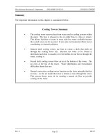
In general, a steam trap consists of a
Figure 16 Ball Float Steam Trap
valve and a device or arrangement that
causes the valve to open and close as
necessary to drain the condensate from
piping without allowing the escape of
steam. Steam traps are installed at low
points in the system or machinery to be
drained. Some types of steam traps that
are used in DOE facilities are described
in this chapter.
Ball Float Steam Trap
A ball float steam trap is illustrated in
Figure 16. The valve of this trap is
connected to the float in such a way that
the valve opens when the float rises.
When the trap is in operation, the steam
and any water that may be mixed with it
flows into the float chamber. The water,
being heavier than the steam, falls to the bottom of the trap, causing the water level to rise. As
the water level rises, it lifts the float; thus lifting the valve plug and opening the valve. The
condensate drains out and the float moves down to a lower position, closing the valve before the
condensate level gets low enough to allow steam to escape. The condensate that passes out of
the trap is returned to the feed system.
Rev. 0 ME-05
Page 35