Mechanical Science HandbooksMechanical Science Handbooks 20000 Part 4 potx
Bạn đang xem bản rút gọn của tài liệu. Xem và tải ngay bản đầy đủ của tài liệu tại đây (783.71 KB, 13 trang )
TYPES OF VALVES DOE-HDBK-1018/2-93 Valves
Port Patterns
Ball valves are available in the venturi, reduced, and full port pattern. The full port
pattern has a ball with a bore equal to the inside diameter of the pipe.
Valve Materials
Balls are usually metallic in metallic bodies with trim (seats) produced from elastomeric
(elastic materials resembling rubber) materials. Plastic construction is also available.
The resilient seats for ball valves are made from various elastomeric material. The most
common seat materials are teflon (TFE), filled TFE, Nylon, Buna-N, Neoprene, and
combinations of these materials. Because of the elastomeric materials, these valves
cannot be used at elevated temperatures. Care must be used in the selection of the seat
material to ensure that it is compatible with the materials being handled by the valve.
Ball Valve Stem Design
The stem in a ball valve is not fastened to the ball. It normally has a rectangular portion at the
ball end which fits into a slot cut into the ball. The enlargement permits rotation of the ball as
the stem is turned.
Ball Valve Bonnet Design
A bonnet cap fastens to the body, which holds the stem assembly and ball in place. Adjustment
of the bonnet cap permits compression of the packing, which supplies the stem seal. Packing for
ball valve stems is usually in the configuration of die-formed packing rings normally of TFE,
TFE-filled, or TFE-impregnated material. Some ball valve stems are sealed by means of O-rings
rather than packing.
Ball Valve Position
Some ball valves are equipped with stops that permit only 90° rotation. Others do not have
stops and may be rotated 360°. With or without stops, a 90° rotation is all that is required for
closing or opening a ball valve.
The handle indicates valve ball position. When the handle lies along the axis of the valve, the
valve is open. When the handle lies 90° across the axis of the valve, the valve is closed. Some
ball valve stems have a groove cut in the top face of the stem that shows the flowpath through
the ball. Observation of the groove position indicates the position of the port through the ball.
This feature is particularly advantageous on multiport ball valves.
ME-04 Rev. 0
Page 20
Valves DOE-HDBK-1018/2-93 TYPES OF VALVES
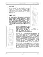
Plug Valves
A plug valve is a rotational motion valve used to stop or start fluid flow. The name is derived
from the shape of the disk, which resembles a plug. A plug valve is shown in Figure 13. The
simplest form of a plug valve is the petcock. The body of a plug valve is machined to receive
the tapered or cylindrical plug. The disk is a solid plug with a bored passage at a right angle to
the longitudinal axis of the plug.
In the open position, the passage in the plug lines up with the inlet and outlet ports of the valve
Figure 13 Plug Valve
body. When the plug is turned 90° from the open position, the solid part of the plug blocks the
ports and stops fluid flow.
Rev. 0 ME-04
Page 21
TYPES OF VALVES DOE-HDBK-1018/2-93 Valves
Plug valves are available in either a lubricated or nonlubricated design and with a variety of
styles of port openings through the plug as well as a number of plug designs.
Plug Ports
An important characteristic of the plug valve is its easy adaptation to multiport construction.
Multiport valves are widely used. Their installation simplifies piping, and they provide a more
convenient operation than multiple gate valves. They also eliminate pipe fittings. The use of
a multiport valve, depending upon the number of ports in the plug valve, eliminates the need of
as many as four conventional shutoff valves.
Plug valves are normally used in non-throttling, on-off operations, particularly where frequent
operation of the valve is necessary. These valves are not normally recommended for throttling
service because, like the gate valve, a high percentage of flow change occurs near shutoff at high
velocity. However, a diamond-shaped port has been developed for throttling service.
Multiport Plug Valves
Multiport valves are particularly advantageous on transfer lines and for diverting services. A
single multiport valve may be installed in lieu of three or four gate valves or other types of
shutoff valve. A disadvantage is that many multiport valve configurations do not completely
shut off flow.
In most cases, one flowpath is always open. These valves are intended to divert the flow of one
line while shutting off flow from the other lines. If complete shutoff of flow is a requirement,
it is necessary that a style of multiport valve be used that permits this, or a secondary valve
should be installed on the main line ahead of the multiport valve to permit complete shutoff of
flow.
In some multiport configurations, simultaneous flow to more than one port is also possible. Great
care should be taken in specifying the particular port arrangement required to guarantee that
proper operation will be possible.
Plug Valve Disks
Plugs are either round or cylindrical with a taper. They may have various types of port
openings, each with a varying degree of area relative to the corresponding inside diameter of the
pipe.
Rectangular Port Plug
The most common port shape is the rectangular port. The rectangular port represents at
least 70% of the corresponding pipe's cross-sectional area.
ME-04 Rev. 0
Page 22
Valves DOE-HDBK-1018/2-93 TYPES OF VALVES
Round Port Plug
Round port plug is a term that describes a valve that has a round opening through the
plug. If the port is the same size or larger than the pipe's inside diameter, it is referred
to as a full port. If the opening is smaller than the pipe's inside diameter, the port is
referred to as a standard round port. Valves having standard round ports are used only
where restriction of flow is unimportant.
Diamond Port Plug
A diamond port plug has a diamond-shaped port through the plug. This design is for
throttling service. All diamond port valves are venturi restricted flow type.
Lubricated Plug Valve Design
Clearances and leakage prevention are the chief considerations in plug valves. Many plug valves
are of all metal construction. In these versions, the narrow gap around the plug can allow
leakage. If the gap is reduced by sinking the taper plug deeper into the body, actuation torque
climbs rapidly and galling can occur. To remedy this condition, a series of grooves around the
body and plug port openings is supplied with grease prior to actuation. Applying grease
lubricates the plug motion and seals the gap between plug and body. Grease injected into a
fitting at the top of the stem travels down through a check valve in the passageway, past the plug
top to the grooves on the plug, and down to a well below the plug. The lubricant must be
compatible with the temperature and nature of the fluid. All manufacturers of lubricated plug
valves have developed a series of lubricants that are compatible with a wide range of media.
Their recommendation should be followed as to which lubricant is best suited for the service.
The most common fluids controlled by plug valves are gases and liquid hydrocarbons. Some
water lines have these valves, provided that lubricant contamination is not a serious danger.
Lubricated plug valves may be as large as 24 inches and have pressure capabilities up to 6000
psig. Steel or iron bodies are available. The plug can be cylindrical or tapered.
Nonlubricated Plugs
There are two basic types of nonlubricated plug valves: lift-type and elastomer sleeve or plug
coated. Lift-type valves provide a means of mechanically lifting the tapered plug slightly to
disengage it from the seating surface to permit easy rotation. The mechanical lifting can be
accomplished with a cam or external lever.
Rev. 0 ME-04
Page 23
TYPES OF VALVES DOE-HDBK-1018/2-93 Valves
In a common, nonlubricated, plug valve having an elastomer sleeve, a sleeve of TFE completely
surrounds the plug. It is retained and locked in place by a metal body. This design results in
a primary seal being maintained between the sleeve and the plug at all times regardless of
position. The TFE sleeve is durable and inert to all but a few rarely encountered chemicals. It
also has a low coefficient of friction and is, therefore, self-lubricating.
Manually Operated Plug Valve Installation
When installing plug valves, care should be taken to allow room for the operation of the handle,
lever, or wrench. The manual operator is usually longer than the valve, and it rotates to a
position parallel to the pipe from a position 90° to the pipe.
Plug Valve Glands
The gland of the plug valve is equivalent to the bonnet of a gate or globe valve. The gland
secures the stem assembly to the valve body. There are three general types of glands: single
gland, screwed gland, and bolted gland.
To ensure a tight valve, the plug must be seated at all times. Gland adjustment should be kept
tight enough to prevent the plug from becoming unseated and exposing the seating surfaces to
the live fluid. Care should be exercised to not overtighten the gland, which will result in a
metal-to-metal contact between the body and the plug. Such a metal-to-metal contact creates an
additional force which will require extreme effort to operate the valve.
Diaphragm Valves
A diaphragm valve is a linear motion valve that is used to start, regulate, and stop fluid flow.
The name is derived from its flexible disk, which mates with a seat located in the open area at
the top of the valve body to form a seal. A diaphragm valve is illustrated in Figure 14.
Figure 14 Straight Through Diaphragm Valve
ME-04 Rev. 0
Page 24
Valves DOE-HDBK-1018/2-93 TYPES OF VALVES
Diaphragm valves are, in effect, simple "pinch clamp" valves. A resilient, flexible diaphragm is
connected to a compressor by a stud molded into the diaphragm. The compressor is moved up
and down by the valve stem. Hence, the diaphragm lifts when the compressor is raised. As the
compressor is lowered, the diaphragm is pressed against the contoured bottom in the straight
through valve illustrated in Figure 14 or the body weir in the weir-type valve illustrated in
Figure 15.
Diaphragm valves can also be used for throttling service. The weir-type is the better throttling
valve but has a limited range. Its throttling characteristics are essentially those of a quick-
opening valve because of the large shutoff area along the seat.
A weir-type diaphragm valve is available to control small flows. It uses a two-piece compressor
component. Instead of the entire diaphragm lifting off the weir when the valve is opened, the
first increments of stem travel raise an inner compressor component that causes only the central
part of the diaphragm to lift. This creates a relatively small opening through the center of the
valve. After the inner compressor is completely open, the outer compressor component is raised
along with the inner compressor and the remainder of the throttling is similar to the throttling that
takes place in a conventional valve.
Diaphragm valves are particularly suited for the handling of corrosive fluids, fibrous slurries,
radioactive fluids, or other fluids that must remain free from contamination.
Diaphragm Construction
The operating mechanism of a diaphragm valve is not exposed to the media within the pipeline.
Sticky or viscous fluids cannot get into the bonnet to interfere with the operating mechanism.
Many fluids that would clog, corrode, or gum up the working parts of most other types of valves
will pass through a diaphragm valve without causing problems. Conversely, lubricants used for
the operating mechanism cannot be allowed to contaminate the fluid being handled. There are
no packing glands to maintain and no possibility of stem leakage. There is a wide choice of
available diaphragm materials. Diaphragm life depends upon the nature of the material handled,
temperature, pressure, and frequency of operation.
Some elastomeric diaphragm materials may be unique in their excellent resistance to certain
chemicals at high temperatures. However, the mechanical properties of any elastomeric material
will be lowered at the higher temperature with possible destruction of the diaphragm at high
pressure. Consequently, the manufacturer should be consulted when they are used in elevated
temperature applications.
Rev. 0 ME-04
Page 25
TYPES OF VALVES DOE-HDBK-1018/2-93 Valves
Figure 15 Weir Diaphragm Valve
ME-04 Rev. 0
Page 26
Valves DOE-HDBK-1018/2-93 TYPES OF VALVES
All elastomeric materials operate best below 150°F. Some will function at higher temperatures.
Viton, for example, is noted for its excellent chemical resistance and stability at high
temperatures. However, when fabricated into a diaphragm, Viton is subject to lowered tensile
strength just as any other elastomeric material would be at elevated temperatures. Fabric
bonding strength is also lowered at elevated temperatures, and in the case of Viton, temperatures
may be reached where the bond strength could become critical.
Fluid concentrations is also a consideration for diaphragm selection. Many of the diaphragm
materials exhibit satisfactory corrosion resistance to certain corrodents up to a specific
concentration and/or temperature. The elastomer may also have a maximum temperature
limitation based on mechanical properties which could be in excess of the allowable operating
temperature depending upon its corrosion resistance. This should be checked from a corrosion
table.
Diaphragm Valve Stem Assemblies
Diaphragm valves have stems that do not rotate. The valves are available with indicating and
nonindicating stems. The indicating stem valve is identical to the nonindicating stem valve
except that a longer stem is provided to extend up through the handwheel. For the nonindicating
stem design, the handwheel rotates a stem bushing that engages the stem threads and moves the
stem up and down. As the stem moves, so does the compressor that is pinned to the stem. The
diaphragm, in turn, is secured to the compressor.
Diaphragm Valve Bonnet Assemblies
Some diaphragm valves use a quick-opening bonnet and lever operator. This bonnet is
interchangeable with the standard bonnet on conventional weir-type bodies. A 90° turn of the
lever moves the diaphragm from full open to full closed. Diaphragm valves may also be
equipped with chain wheel operators, extended stems, bevel gear operators, air operators, and
hydraulic operators.
Many diaphragm valves are used in vacuum service. Standard bonnet construction can be
employed in vacuum service through 4 inches in size. On valves 4 inches and larger, a sealed,
evacuated, bonnet should be employed. This is recommended to guard against premature
diaphragm failure.
Sealed bonnets are supplied with a seal bushing on the nonindicating types and a seal bushing
plus O-ring on the indicating types. Construction of the bonnet assembly of a diaphragm valve
is illustrated in Figure 15. This design is recommended for valves that are handling dangerous
liquids and gases. In the event of a diaphragm failure, the hazardous materials will not be
released to the atmosphere. If the materials being handled are extremely hazardous, it is
recommended that a means be provided to permit a safe disposal of the corrodents from the
bonnet.
Rev. 0 ME-04
Page 27
TYPES OF VALVES DOE-HDBK-1018/2-93 Valves
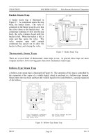
Reducing Valves
Reducing valves automatically reduce supply pressure to a preselected pressure as long as the
supply pressure is at least as high as the selected pressure. As illustrated in Figure 16, the
principal parts of the reducing valve are the main valve; an upward-seating valve that has a
piston on top of its valve stem, an upward-seating auxiliary (or controlling) valve, a controlling
diaphragm, and an adjusting spring and screw.
Figure 16 Variable Reducing Valve
Reducing valve operation is controlled by high pressure at the valve inlet and the adjusting screw
on top of the valve assembly. The pressure entering the main valve assists the main valve
spring in keeping the reducing valve closed by pushing upward on the main valve disk.
However, some of the high pressure is bled to an auxiliary valve on top of the main valve. The
auxiliary valve controls the admission of high pressure to the piston on top of the main valve.
The piston has a larger surface area than the main valve disk, resulting in a net downward force
to open the main valve. The auxiliary valve is controlled by a controlling diaphragm located
directly over the auxiliary valve.
ME-04 Rev. 0
Page 28
Valves DOE-HDBK-1018/2-93 TYPES OF VALVES
The controlling diaphragm transmits a downward force that tends to open the auxiliary valve.
The downward force is exerted by the adjusting spring, which is controlled by the adjusting
screw. Reduced pressure from the main valve outlet is bled back to a chamber beneath the
diaphragm to counteract the downward force of the adjusting spring. The position of the
auxiliary valve, and ultimately the position of the main valve, is determined by the position of
the diaphragm. The position of the diaphragm is determined by the strength of the opposing
forces of the downward force of the adjusting spring versus the upward force of the outlet
reduced pressure. Other reducing valves work on the same basic principle, but may use gas,
pneumatic, or hydraulic controls in place of the adjusting spring and screw.
Non-variable reducing valves, illustrated in Figure 17, replace the adjusting spring and screw
with a pre-pressurized dome over the diaphragm. The valve stem is connected either directly
or indirectly to the diaphragm. The valve spring below the diaphragm keeps the valve closed.
As in the variable valve, reduced pressure is bled through an orifice to beneath the diaphragm
to open the valve. Valve position is determined by the strength of the opposing forces of the
downward force of the pre-pressurized dome versus the upward force of the outlet-reduced
pressure.
Figure 17 Non-Variable Reducing Valve
Rev. 0 ME-04
Page 29
TYPES OF VALVES DOE-HDBK-1018/2-93 Valves
Non-variable reducing valves eliminate the need for the intermediate auxiliary valve found in
variable reducing valves by having the opposing forces react directly on the diaphragm.
Therefore, non-variable reducing valves are more responsive to large pressure variations and are
less susceptible to failure than are variable reducing valves.
Pinch Valves
The relatively inexpensive pinch valve,
Figure 18 Pinch Valves
illustrated in Figure 18, is the simplest
in any valve design. It is simply an
industrial version of the pinch cock
used in the laboratory to control the
flow of fluids through rubber tubing.
Pinch valves are suitable for on-off
and throttling services. However, the
effective throttling range is usually
between 10% and 95% of the rated
flow capacity.
Pinch valves are ideally suited for the
handling of slurries, liquids with large
amounts of suspended solids, and
systems that convey solids
pneumatically. Because the operating
mechanism is completely isolated from
the fluid, these valves also find
application where corrosion or metal
contamination of the fluid might be a
problem.
The pinch control valve consists of a sleeve molded of rubber or other synthetic material and
a pinching mechanism. All of the operating portions are completely external to the valve. The
molded sleeve is referred to as the valve body.
Pinch valve bodies are manufactured of natural and synthetic rubbers and plastics which have
good abrasion resistance properties. These properties permit little damage to the valve sleeve,
thereby providing virtually unimpeded flow. Sleeves are available with either extended hubs and
clamps designed to slip over a pipe end, or with a flanged end having standard dimensions.
ME-04 Rev.0
Page 30
Valves DOE-HDBK-1018/2-93 TYPES OF VALVES
Pinch Valve Bodies
Pinch valves have molded bodies reinforced with fabric. Pinch valves generally have a
maximum operating temperature of 250
o
F. At 250
o
F, maximum operating pressure varies
generally from 100 psig for a 1-inch diameter valve and decreases to 15 psig for a 12-inch
diameter valve. Special pinch valves are available for temperature ranges of -100
o
F to 550
o
F
and operating pressures of 300 psig.
Most pinch valves are supplied with the sleeve (valve body) exposed. Another style fully
encloses the sleeve within a metallic body. This type controls flow either with the conventional
wheel and screw pinching device, hydraulically, or pneumatically with the pressure of the liquid
or gas within the metal case forcing the sleeve walls together to shut off flow.
Most exposed sleeve valves have limited vacuum application because of the tendency of the
sleeves to collapse when vacuum is applied. Some of the encased valves can be used on vacuum
service by applying a vacuum within the metal casing and thus preventing the collapse of the
sleeve.
Figure 19 Typical Butterfly Valve
Butterfly Valves
A butterfly valve, illustrated in
Figure 19, is a rotary motion
valve that is used to stop,
regulate, and start fluid flow.
Butterfly valves are easily and
quickly operated because a 90
o
rotation of the handle moves the
disk from a fully closed to fully
opened position. Larger butterfly
valves are actuated by handwheels
connected to the stem through
gears that provide mechanical
advantage at the expense of speed.
Butterfly valves possess many
advantages over gate, globe, plug,
and ball valves, especially for
large valve applications. Savings
in weight, space, and cost are the
most obvious advantages. The
maintenance costs are usually low
because there are a minimal
number of moving parts and there
are no pockets to trap fluids.
Rev. 0 ME-04
Page 31
TYPES OF VALVES DOE-HDBK-1018/2-93 Valves
Butterfly valves are especially well-suited for the handling of large flows of liquids or gases at
relatively low pressures and for the handling of slurries or liquids with large amounts of
suspended solids.
Butterfly valves are built on the principle of a pipe damper. The flow control element is a disk
of approximately the same diameter as the inside diameter of the adjoining pipe, which rotates
on either a vertical or horizontal axis. When the disk lies parallel to the piping run, the valve
is fully opened. When the disk approaches the perpendicular position, the valve is shut.
Intermediate positions, for throttling purposes, can be secured in place by handle-locking
devices.
Butterfly Valve Seat Construction
Stoppage of flow is accomplished by the valve disk sealing against a seat that is on the inside
diameter periphery of the valve body. Many butterfly valves have an elastomeric seat against
which the disk seals. Other butterfly valves have a seal ring arrangement that uses a clamp-ring
and backing-ring on a serrated edged rubber ring. This design prevents extrusion of the O-rings.
In early designs, a metal disk was used to seal against a metal seat. This arrangement did not
provide a leak-tight closure, but did provide sufficient closure in some applications (i.e., water
distribution lines).
Butterfly Valve Body Construction
Butterfly valve body construction varies. The most economical is the wafer type that fits
between two pipeline flanges. Another type, the lug wafer design, is held in place between two
pipe flanges by bolts that join the two flanges and pass through holes in the valve's outer casing.
Butterfly valves are available with conventional flanged ends for bolting to pipe flanges, and in
a threaded end construction.
Butterfly Valve Disk and Stem Assemblies
The stem and disk for a butterfly valve are separate pieces. The disk is bored to receive the
stem. Two methods are used to secure the disk to the stem so that the disk rotates as the stem
is turned. In the first method, the disk is bored through and secured to the stem with bolts or
pins. The alternate method involves boring the disk as before, then shaping the upper stem bore
to fit a squared or hex-shaped stem. This method allows the disk to "float" and seek its center
in the seat. Uniform sealing is accomplished and external stem fasteners are eliminated. This
method of assembly is advantageous in the case of covered disks and in corrosive applications.
In order for the disk to be held in the proper position, the stem must extend beyond the bottom
of the disk and fit into a bushing in the bottom of the valve body. One or two similar bushings
are along the upper portion of the stem as well. These bushings must be either resistant to the
media being handled or sealed so that the corrosive media cannot come into contact with them.
ME-04 Rev.0
Page 32