Mechanical Science HandbooksMechanical Science Handbooks 10000 Part 11 doc
Bạn đang xem bản rút gọn của tài liệu. Xem và tải ngay bản đầy đủ của tài liệu tại đây (303.7 KB, 10 trang )
Pumps DOE-HDBK-1018/1-93 CENTRIFUGAL PUMPS
Figure 9 Multi-Stage Centrifugal Pump
Centrifugal Pump Components
Centrifugal pumps vary in design and construction from simple pumps with relatively few parts
to extremely complicated pumps with hundreds of individual parts. Some of the most common
components found in centrifugal pumps are wearing rings, stuffing boxes, packing, and lantern
rings. These components are shown in Figure 10 and described on the following pages.
Wearing Rings
Centrifugal pumps contain rotating impellers within stationary pump casings. To allow
the impeller to rotate freely within the pump casing, a small clearance is designed to be
maintained between the impeller and the pump casing. To maximize the efficiency of a
centrifugal pump, it is necessary to minimize the amount of liquid leaking through this
clearance from the high pressure or discharge side of the pump back to the low pressure
or suction side.
Rev. 0 ME-03
Page 7
CENTRIFUGAL PUMPS DOE-HDBK-1018/1-93 Pumps
Some wear or erosion will occur at the point where the impeller and the pump casing
Figure 10 Centrifugal Pump Components
nearly come into contact. This wear is due to the erosion caused by liquid leaking
through this tight clearance and other causes. As wear occurs, the clearances become
larger and the rate of leakage increases. Eventually, the leakage could become
unacceptably large and maintenance would be required on the pump.
To minimize the cost of pump maintenance, many centrifugal pumps are designed with
wearing rings. Wearing rings are replaceable rings that are attached to the impeller and/or
the pump casing to allow a small running clearance between the impeller and the pump
casing without causing wear of the actual impeller or pump casing material. These
wearing rings are designed to be replaced periodically during the life of a pump and
prevent the more costly replacement of the impeller or the casing.
ME-03 Rev. 0
Page 8
Pumps DOE-HDBK-1018/1-93 CENTRIFUGAL PUMPS
Stuffing Box
In almost all centrifugal pumps, the rotating shaft that drives the impeller penetrates the
pressure boundary of the pump casing. It is important that the pump is designed properly
to control the amount of liquid that leaks along the shaft at the point that the shaft
penetrates the pump casing. There are many different methods of sealing the shaft
penetration of the pump casing. Factors considered when choosing a method include the
pressure and temperature of the fluid being pumped, the size of the pump, and the
chemical and physical characteristics of the fluid being pumped.
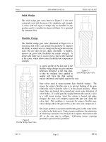
One of the simplest types of shaft seal is the stuffing box. The stuffing box is a
cylindrical space in the pump casing surrounding the shaft. Rings of packing material
are placed in this space. Packing is material in the form of rings or strands that is placed
in the stuffing box to form a seal to control the rate of leakage along the shaft. The
packing rings are held in place by a gland. The gland is, in turn, held in place by studs
with adjusting nuts. As the adjusting nuts are tightened, they move the gland in and
compress the packing. This axial compression causes the packing to expand radially,
forming a tight seal between the rotating shaft and the inside wall of the stuffing box.
The high speed rotation of the shaft generates a significant amount of heat as it rubs
against the packing rings. If no lubrication and cooling are provided to the packing, the
temperature of the packing increases to the point where damage occurs to the packing,
the pump shaft, and possibly nearby pump bearings. Stuffing boxes are normally
designed to allow a small amount of controlled leakage along the shaft to provide
lubrication and cooling to the packing. The leakage rate can be adjusted by tightening
and loosening the packing gland.
Lantern Ring
It is not always possible to use a standard stuffing box to seal the shaft of a centrifugal
pump. The pump suction may be under a vacuum so that outward leakage is impossible
or the fluid may be too hot to provide adequate cooling of the packing. These conditions
require a modification to the standard stuffing box.
One method of adequately cooling the packing under these conditions is to include a
lantern ring. A lantern ring is a perforated hollow ring located near the center of the
packing box that receives relatively cool, clean liquid from either the discharge of the
pump or from an external source and distributes the liquid uniformly around the shaft to
provide lubrication and cooling. The fluid entering the lantern ring can cool the shaft and
packing, lubricate the packing, or seal the joint between the shaft and packing against
leakage of air into the pump in the event the pump suction pressure is less than that of
the atmosphere.
Rev. 0 ME-03
Page 9
CENTRIFUGAL PUMPS DOE-HDBK-1018/1-93 Pumps
Mechanical Seals
In some situations, packing material is not adequate for sealing the shaft. One common
alternative method for sealing the shaft is with mechanical seals. Mechanical seals
consist of two basic parts, a rotating element attached to the pump shaft and a stationary
element attached to the pump casing. Each of these elements has a highly polished
sealing surface. The polished faces of the rotating and stationary elements come into
contact with each other to form a seal that prevents leakage along the shaft.
Summary
The important information in this chapter is summarized below.
Centrifugal Pumps Summary
The impeller contains rotating vanes that impart a radial and rotary motion to the
liquid.
The volute collects the liquid discharged from the impeller at high velocity and
gradually causes a reduction in fluid velocity by increasing the flow area, converting
the velocity head to a static head.
A diffuser increases the efficiency of a centrifugal pump by allowing a more gradual
expansion and less turbulent area for the liquid to slow as the flow area expands.
Packing material provides a seal in the area where the pump shaft penetrates the
pump casing.
Wearing rings are replaceable rings that are attached to the impeller and/or the
pump casing to allow a small running clearance between the impeller and pump
casing without causing wear of the actual impeller or pump casing material.
The lantern ring is inserted between rings of packing in the stuffing box to receive
relatively cool, clean liquid and distribute the liquid uniformly around the shaft to
provide lubrication and cooling to the packing.
ME-03 Rev. 0
Page 10
Pumps DOE-HDBK-1018/1-93 CENTRIFUGAL PUMP OPERATION
CENTRIFUGAL PUMP OPERATION
Improper operation of centrifugal pumps can result in damage to the pump and
loss of function of the system that the pump is installed in. It is helpful to know
what conditions can lead to pump damage to allow better understanding of pump
operating procedures and how the procedures aid the operator in avoiding pump
damage.
EO 1.3 DEFINE the following terms:
a. Net Positive Suction
Head Available
b. Cavitation
c. Gas binding
d. Shutoff head
e. Pump runout
EO 1.4 STATE the relationship between net positive suction head
available and net positive suction head required that is
necessary to avoid cavitation.
EO 1.5 LIST three indications that a centrifugal pump may be
cavitating.
EO 1.6 LIST five changes that can be made in a pump or its
surrounding system that can reduce cavitation.
EO 1.7 LIST three effects of cavitation.
EO 1.8 DESCRIBE the shape of the characteristic curve for a
centrifugal pump.
EO 1.9 DESCRIBE how centrifugal pumps are protected from
the conditions of dead heading and pump runout.
Introduction
Many centrifugal pumps are designed in a manner that allows the pump to operate continuously
for months or even years. These centrifugal pumps often rely on the liquid that they are
pumping to provide cooling and lubrication to the pump bearings and other internal components
of the pump. If flow through the pump is stopped while the pump is still operating, the pump
will no longer be adequately cooled and the pump can quickly become damaged. Pump damage
can also result from pumping a liquid whose temperature is close to saturated conditions.
Rev. 0 ME-03
Page 11
CENTRIFUGAL PUMP OPERATION DOE-HDBK-1018/1 Pumps
Cavitation
The flow area at the eye of the pump impeller is usually smaller than either the flow area of the
pump suction piping or the flow area through the impeller vanes. When the liquid being pumped
enters the eye of a centrifugal pump, the decrease in flow area results in an increase in flow
velocity accompanied by a decrease in pressure. The greater the pump flow rate, the greater the
pressure drop between the pump suction and the eye of the impeller. If the pressure drop is
large enough, or if the temperature is high enough, the pressure drop may be sufficient to cause
the liquid to flash to vapor when the local pressure falls below the saturation pressure for the
fluid being pumped. Any vapor bubbles formed by the pressure drop at the eye of the impeller
are swept along the impeller vanes by the flow of the fluid. When the bubbles enter a region
where local pressure is greater than saturation pressure farther out the impeller vane, the vapor
bubbles abruptly collapse. This process of the formation and subsequent collapse of vapor
bubbles in a pump is called cavitation.
Cavitation in a centrifugal pump has a significant effect on pump performance. Cavitation
degrades the performance of a pump, resulting in a fluctuating flow rate and discharge pressure.
Cavitation can also be destructive to pumps internal components. When a pump cavitates, vapor
bubbles form in the low pressure region directly behind the rotating impeller vanes. These vapor
bubbles then move toward the oncoming impeller vane, where they collapse and cause a physical
shock to the leading edge of the impeller vane. This physical shock creates small pits on the
leading edge of the impeller vane. Each individual pit is microscopic in size, but the cumulative
effect of millions of these pits formed over a period of hours or days can literally destroy a pump
impeller. Cavitation can also cause excessive pump vibration, which could damage pump
bearings, wearing rings, and seals.
A small number of centrifugal pumps are designed to operate under conditions where cavitation
is unavoidable. These pumps must be specially designed and maintained to withstand the small
amount of cavitation that occurs during their operation. Most centrifugal pumps are not designed
to withstand sustained cavitation.
Noise is one of the indications that a centrifugal pump is cavitating. A cavitating pump can
sound like a can of marbles being shaken. Other indications that can be observed from a remote
operating station are fluctuating discharge pressure, flow rate, and pump motor current. Methods
to stop or prevent cavitation are presented in the following paragraphs.
Net Positive Suction Head
To avoid cavitation in centrifugal pumps, the pressure of the fluid at all points within the pump
must remain above saturation pressure. The quantity used to determine if the pressure of the
liquid being pumped is adequate to avoid cavitation is the net positive suction head (NPSH).
The net positive suction head available (NPSH
A
) is the difference between the pressure at the
suction of the pump and the saturation pressure for the liquid being pumped. The net positive
suction
head required (NPSH
R
) is the minimum net positive suction head necessary to avoid
cavitation.
ME-03 Rev. 0
Page 12
Pumps DOE-HDBK-1018/1-93 CENTRIFUGAL PUMP OPERATION
The condition that must exist to avoid cavitation is that the net positive suction head available
must be greater than or equal to the net positive suction head required. This requirement can be
stated mathematically as shown below.
NPSH
A
≥ NPSH
R
A formula for NPSH
A
can be stated as the following equation.
NPSH
A
= P
suction
- P
saturation
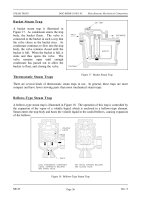
When a centrifugal pump is taking suction from a tank or other reservoir, the pressure at the
suction of the pump is the sum of the absolute pressure at the surface of the liquid in the tank
plus the pressure due to the elevation difference between the surface of liquid in the tank and
the pump suction less the head losses due to friction in the suction line from the tank to the
pump.
NPSH
A
= P
a
+ P
st
- h
f
- P
sat
Where:
NPSH
A
= net positive suction head available
P
a
= absolute pressure on the surface of the liquid
P
st
= pressure due to elevation between liquid surface and pump suction
h
f
= head losses in the pump suction piping
P
sat
= saturation pressure of the liquid being pumped
Preventing Cavitation
If a centrifugal pump is cavitating, several changes in the system design or operation may be
necessary to increase the NPSH
A
above the NPSH
R
and stop the cavitation. One method for
increasing the NPSH
A
is to increase the pressure at the suction of the pump. For example, if a
pump is taking suction from an enclosed tank, either raising the level of the liquid in the tank or
increasing the pressure in the space above the liquid increases suction pressure.
It is also possible to increase the NPSH
A
by decreasing the temperature of the liquid being
pumped. Decreasing the temperature of the liquid decreases the saturation pressure, causing
NPSH
A
to increase. Recall from the previous module on heat exchangers that large steam
condensers usually subcool the condensate to less than the saturation temperature, called
condensate depression, to prevent cavitation in the condensate pumps.
If the head losses in the pump suction piping can be reduced, the NPSH
A
will be increased.
Various methods for reducing head losses include increasing the pipe diameter, reducing the
number of elbows, valves, and fittings in the pipe, and decreasing the length of the pipe.
Rev. 0 ME-03
Page 13
CENTRIFUGAL PUMP OPERATION DOE-HDBK-1018/1 Pumps
It may also be possible to stop cavitation by reducing the NPSH
R
for the pump. The NPSH
R
is
not a constant for a given pump under all conditions, but depends on certain factors. Typically,
the NPSH
R
of a pump increases significantly as flow rate through the pump increases.
Therefore, reducing the flow rate through a pump by throttling a discharge valve decreases
NPSH
R
. NPSH
R
is also dependent upon pump speed. The faster the impeller of a pump rotates,
the greater the NPSH
R
. Therefore, if the speed of a variable speed centrifugal pump is reduced,
the NPSH
R
of the pump decreases. However, since a pump's flow rate is most often dictated
by the needs of the system on which it is connected, only limited adjustments can be made
without starting additional parallel pumps, if available.
The net positive suction head required to prevent cavitation is determined through testing by the
pump manufacturer and depends upon factors including type of impeller inlet, impeller design,
pump flow rate, impeller rotational speed, and the type of liquid being pumped. The
manufacturer typically supplies curves of NPSH
R
as a function of pump flow rate for a particular
liquid (usually water) in the vendor manual for the pump.
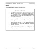
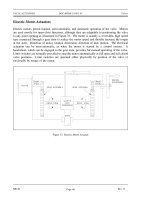
Centrifugal Pump Characteristic Curves
For a given centrifugal pump operating at a constant speed, the flow rate through the pump is
Figure 11 Centrifugal Pump Characteristic Curve
dependent upon the differential pressure or head developed by the pump. The lower the pump
head, the higher the flow rate. A vendor manual for a specific pump usually contains a curve
of pump flow rate versus pump head called a pump characteristic curve. After a pump is
installed in a system, it is usually tested to ensure that the flow rate and head of the pump are
within the required specifications. A typical centrifugal pump characteristic curve is shown in
Figure 11.
There are several terms associated with the pump characteristic curve that must be defined.
Shutoff head is the maximum head that can be developed by a centrifugal pump operating at a
set speed. Pump runout is the maximum flow that can be developed by a centrifugal pump
without damaging the pump. Centrifugal pumps must be designed and operated to be protected
from the conditions of pump runout or operating at shutoff head. Additional information may
be found in the handbook on Thermodynamics, Heat Transfer, and Fluid Flow.
ME-03 Rev. 0
Page 14
Pumps DOE-HDBK-1018/1-93 CENTRIFUGAL PUMP OPERATION
Centrifugal Pump Protection
A centrifugal pump is dead-headed when it is operated with no flow through it, for example, with
a closed discharge valve or against a seated check valve. If the discharge valve is closed and
there is no other flow path available to the pump, the impeller will churn the same volume of
water as it rotates in the pump casing. This will increase the temperature of the liquid (due to
friction) in the pump casing to the point that it will flash to vapor. The vapor can interrupt the
cooling flow to the pump's packing and bearings, causing excessive wear and heat. If the pump
is run in this condition for a significant amount of time, it will become damaged.
When a centrifugal pump is installed in a system such that it may be subjected to periodic shutoff
head conditions, it is necessary to provide some means of pump protection. One method for
protecting the pump from running dead-headed is to provide a recirculation line from the pump
discharge line upstream of the discharge valve, back to the pump's supply source. The
recirculation line should be sized to allow enough flow through the pump to prevent overheating
and damage to the pump. Protection may also be accomplished by use of an automatic flow
control device.
Centrifugal pumps must also be protected from runout. Runout can lead to cavitation and can
also cause overheating of the pump's motor due to excessive currents. One method for ensuring
that there is always adequate flow resistance at the pump discharge to prevent excessive flow
through the pump is to place an orifice or a throttle valve immediately downstream of the pump
discharge. Properly designed piping systems are very important to protect from runout.
Gas Binding
Gas binding of a centrifugal pump is a condition where the pump casing is filled with gases or
vapors to the point where the impeller is no longer able to contact enough fluid to function
correctly. The impeller spins in the gas bubble, but is unable to force liquid through the pump.
This can lead to cooling problems for the pump's packing and bearings.
Centrifugal pumps are designed so that their pump casings are completely filled with liquid
during pump operation. Most centrifugal pumps can still operate when a small amount of gas
accumulates in the pump casing, but pumps in systems containing dissolved gases that are not
designed to be self-venting should be periodically vented manually to ensure that gases do not
build up in the pump casing.
Priming Centrifugal Pumps
Most centrifugal pumps are not self-priming. In other words, the pump casing must be filled with
liquid before the pump is started, or the pump will not be able to function. If the pump casing
becomes filled with vapors or gases, the pump impeller becomes gas-bound and incapable of
pumping. To ensure that a centrifugal pump remains primed and does not become gas-bound,
most centrifugal pumps are located below the level of the source from which the pump is to take
its suction. The same effect can be gained by supplying liquid to the pump suction under
pressure supplied by another pump placed in the suction line.
Rev. 0 ME-03
Page 15
CENTRIFUGAL PUMP OPERATION DOE-HDBK-1018/1 Pumps
Summary
The important information in this chapter is summarized below.
Centrifugal Pump Operation Summary
There are three indications that a centrifugal pump is cavitating.
Noise
Fluctuating discharge pressure and flow
Fluctuating pump motor current
Steps that can be taken to stop pump cavitation include:
Increase the pressure at the suction of the pump.
Reduce the temperature of the liquid being pumped.
Reduce head losses in the pump suction piping.
Reduce the flow rate through the pump.
Reduce the speed of the pump impeller.
Three effects of pump cavitation are:
Degraded pump performance
Excessive pump vibration
Damage to pump impeller, bearings, wearing rings, and seals
To avoid pump cavitation, the net positive suction head available must be greater
than the net positive suction head required.
Net positive suction head available is the difference between the pump suction
pressure and the saturation pressure for the liquid being pumped.
Cavitation is the process of the formation and subsequent collapse of vapor bubbles
in a pump.
Gas binding of a centrifugal pump is a condition where the pump casing is filled
with gases or vapors to the point where the impeller is no longer able to contact
enough fluid to function correctly.
Shutoff head is the maximum head that can be developed by a centrifugal pump
operating at a set speed.
ME-03 Rev. 0
Page 16