Bearing Design in Machinery Episode 2 Part 10 docx
Bạn đang xem bản rút gọn của tài liệu. Xem và tải ngay bản đầy đủ của tài liệu tại đây (260.08 KB, 20 trang )
Volume of a Sphere
V
sphere
¼
4
3
pr
3
V
sphere
¼
4
3
pð0:7Þ
3
¼ 1:43 cm
3
Mass of the Ball
m
r
¼ rV ¼ 7:87 g=cm
3
 1:43 cm
3
¼ 11:25 g ¼ 0:011 kg
The shaft and inner ring angular speed is
o ¼
2pN
60
o ¼ 30;000
rev
min
Â
1 min
60 s
Â
2prad
1 rev
¼ 3142 rad=s
Angular Speed of Rolling Elements and Cage
o
C
¼
R
in
R
in
þ R
out
o
shaft
¼
0:025 m
0:025 m þ 0:039 m
 3142 rad=s ¼ 1227 rad=s
Centifugal Force, F
c
F
c
¼ m
r
o
2
C
R
r
¼ 0:011 kg Âð1227 rad=sÞ
2
 0:032 m ¼ 530 N
Thrust Force Component at Outer Ring Contact
S F
x
¼ 0
W
oa
¼ W
ia
¼ 200 N
Radial Component of Inner Ring Contact
W
ir
W
ia
¼ ctan a
i
W
ir
¼ 200 Â ctan 40
¼ 238:4N
Copyright 2003 by Marcel Dekker, Inc. All Rights Reserved.
Radial Component of Outer Ring Contact
S F
y
¼ 0
W
or
¼ W
ir
þ F
c
W
or
¼ 238:4 þ 530 ¼ 768:4N
Outer Ring Contact Angle
tan a
o
¼
W
oa
W
or
tan a
o
¼
200 N
768:4N
¼ 0:26
a
o
¼ 14:5
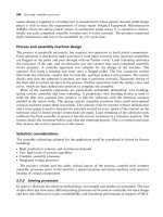
Resultant Force on Outer Ring Contact
The resultant force on the outer ring race, W
o
, is in the direction normal to
surface, as shown in Fig. 12-22. It has two components in the axial and radial
directions:
W
oa
W
o
¼ sin 14:5
W
o
¼
200 N
sin 14:5
¼ 798:8N
Normal Contact Force on Inner Ring Race
The resultant force on the inner ring race, W
i
, is in the direction normal to
surface, as shown in Fig. 12-22. It has two components in the axial and radial
directions:
W
ia
W
o
¼ sin 40
W
i
¼
200 N
sin 40
¼ 311:2N
Example Problem 12-9
An angular contact ball bearing has a contact angle with the inner ring of
a
i
¼ 30
. The thrust load of W ¼ 11;500 N is divided evenly on 14 balls. The
ball has a diameter of d
r
¼ 18 mm. The shaft speed is N ¼ 33;000 RPM. The
conformity ratio R
r
¼ 0:52. The diameter of the outer race at the contact point
with the balls is 118 mm. The balls and rings are made of steel having the
Copyright 2003 by Marcel Dekker, Inc. All Rights Reserved.
following properties: modulus of elasticity E ¼ 2 Â10
11
N=m
2
, Poisson’s ratio
n ¼ 0:3, density r ¼ 7870 kg=m
3
.
a. Find contact angle, a
o
, with the outer ring.
b. Find the contact force with the inner and outer rings.
c. Find the centrifugal force of each rolling element.
d. Find the maximum pressure at the contact with the outer ring.
e. Find the maximum pressure at the contact with the outer ring, given
rings made of steel and balls made of silicone nitride (hybrid bearing).
The properties of silicone nitride are: modulus of elasticity E ¼ 3:14 Â 10
11
N=m
2
, Poisson’s ration n ¼ 0:24, density r ¼ 3200 kg=m
3
.
Solution
a. Contact Angle, a
o
, with Outer Ring
The first step is to find the centrifugal force, F
c
¼ m
r
o
2
C
R
c
, where m
r
is the
mass of a ball, o
C
is the angular speed of the ball center (or cage), and R
c
is the
radius of the ball center circular orbit. The volume and mass of a ball in the
bearing are:
V
sphere
¼
4
3
pr
3
¼
4
3
 p  0:009
3
m
3
¼ 3:05 Â 10
À6
m
3
m
r
¼ rV ¼ 7870 kg=m
3
 3:05 Â10
À6
m
3
¼ 0:024 kg
The shaft and inner ring angular speed is
o ¼
2p  33;000
60
¼ 3456 rad=s
The outer diameter is
R
out
¼
118
2
mm ¼ 59 Â 10
À3
m
In order to find the inner diameter, we assume that a
o
$ a
i
and that the difference
between the outer and inner radius is d
r
cos a
i
. In that case,
R
in
¼ðR
out
À d
r
Þcos a
i
¼ð59 mm À 18 mmÞcos 30
¼ 43:4mm
¼ 43:4 Â10
À3
m
Now it is possible to find the angular speed of a rolling-element center (or cage),
o
c
:
o
c
¼
R
in
R
in
þ R
out
o
shaft
¼
43:4
43:4 þ59
 3456 rad=s ¼ 1465 rad=s
Copyright 2003 by Marcel Dekker, Inc. All Rights Reserved.
The distance between the ball center and the bearing center as R
c
, is required for
the calculation of the centrifugal force.
R
c
¼
R
in
þ R
out
2
¼ 51:2mm
The centrifugal force, F
c
, of each rolling element is in the radial direction:
F
c
¼ m
r
o
2
c
R
c
¼ 0:024 kg  1465
2
 1=s
2
 0:0512 m ¼ 2637 N
The thrust force component of each ball at the outer ring contact is equal to that
of the inner ring:
W
oa
¼ W
ia
¼
11;500 N
14
¼ 821 N
The radial component of inner ring contact is
W
ir
W
ia
¼ ctan a
i
W
ir
¼ 821 Â ctan 30
¼ 1422 N
The radial component of outer ring contact force is
W
or
¼ W
ir
þ F
c
¼ 1421 N þ 2637 N ¼ 4059 N
The outer ring contact angle is solved as follows:
tan a
o
¼
W
oa
W
or
¼
821 N
4058 N
¼ 0:202; a
o
¼ 11:43
b. Contact Force with Inner and Outer Rings
The resultant (normal) component of the outer ring contact is
W
oa
W
o
¼ sin 11:43
W
o
¼
821 N
sin 11:43
¼ 4143 N
The resultant (normal) contact force at the inner ring race is
W
ia
W
i
¼ sin 30
W
i
¼
W
ia
sin 30
¼ 1642 N
c. Rolling-Element Centrifugal Force
From part (a) the centrifugal force is 2637 N, in the radial direction.
Copyright 2003 by Marcel Dekker, Inc. All Rights Reserved.
d. Maximum Pressure at Contact of Outer Ring
The maximum force is at the race of the outer ring, W
o
¼ 4143 N. The radius of
the contact curvatures is
R
1x
¼ R
1y
¼ 9mm
R
2y
¼ R
r
d
r
¼ 18 mm  0:52 ¼ 9:36 mm
R
2x
¼ 59 mm
The equivalent radius of the outer raceway contact in the y-z plane (referred to as
the x plane) is
1
R
x
¼
1
R
1x
À
1
R
2x
¼
1
9mm
À
1
59 mm
R
x
¼
9 Â 59 mm
43:4 À 9
¼ 10:62 mm
The equivalent inner radius in the y plane is
1
R
y
¼
1
R
1y
À
1
R
2y
¼
1
9mm
À
1
9:36 mm
R
y
¼
R
2y
Á R
1y
R
2y
À R
1y
¼
9 Â 9:36 mm
9:36 À9
¼ 234 mm
The equivalent curvature of the inner ring and ball contact is
1
R
eq
¼
1
R
x
þ
1
R
y
¼
1
10:62 mm
þ
1
234 mm
R
eq
¼
R
x
Á R
y
R
x
þ R
y
¼
10:62 Â234 mm
234 þ10:62
¼ 10:16 mm
The ratio a
r
becomes
a
r
¼
R
y
R
x
¼
234 mm
10:62 mm
¼ 22:03
The dimensionless coefficient k is estimated from the ratio a
r
:
k ¼ a
2=p
r
¼ 7:16
Copyright 2003 by Marcel Dekker, Inc. All Rights Reserved.
For the calculation of the ellipsoid radii, the following values are required:
q
a
¼
p
2
À 1 ¼ 0:57
^
EE % 1 þ
q
a
a
r
^
EE % 1 þ
0:57
22:03
¼ 1:025
The shaft and the bearing are made of identical material, so the equivalent
modulus of elasticity is
E
eq
¼
E
1 À n
2
¼
2 Â 10
11
N=m
2
1 À 0:3
2
¼ 2:2 Â10
11
N=m
2
Now the ellipsoid radii a and b can be determined:
a ¼
6 Á
^
EE Á W
max
Á R
eq
p Á k Á E
eq
!
1=3
¼
6 Â 1:025 Â 4143 N Â 10:82 Â 10
À3
m
p  7:16  2:2 Â10
11
N=m
2
1=3
¼ 0:37 mm
b ¼
6 Á k
2
Á
^
EE Á W
max
Á R
eq
p Á E
eq
!
1=3
¼
6 Â 7:16
2
 1:025  4143 N  10:16 Â10
À3
m
p  2:2  10
11
N=m
2
1=3
¼ 2:68 mm
The maximum pressure at the contact with outer ring is
p
max
¼
3
2
Á
W
max
p Á ab
¼
3
2
Á
4134 N
p  0:37  2:68  10
À6
m
2
¼ 1:99 GPa
e. Maximum stress of hybrid bearing
The rings are made of steel and the balls are made of silicone nitride, which has
the following properties:
Modulus of elasticity E ¼ 3:14 Â 10
11
N=m
2
Poisson’s ratio n ¼ 0:24
Density r ¼ 3200 kg=m
3
The major advantage of a hybrid bearing is a lower centrifugal force due to
lower density of the rolling element. However, the modulus of elasticity of
silicone nitride is higher than that of steel, and this can result in a higher
maximum pressure.
Copyright 2003 by Marcel Dekker, Inc. All Rights Reserved.
For a hybrid bearing, it is necessary to consider the equivalent modulus of
elasticity of silicone nitride on steel:
2
E
eq
¼
1 À n
2
21
E
1
þ
1 À n
2
2
E
2
¼
1 À 0:24
2
3:14 Â10
11
N=m
2
þ
1 À 0:3
2
2:0 Â10
11
N=m
2
¼ 0:755 Â10
À11
m
2
=N
E
eq
¼ 2:65 Â10
11
N=m
2
Due to the low density of the balls, the centrifugal force is lower:
m
r
¼ rV ¼ 3200
kg
m
3
 3:05 Â10
À6
m
3
¼ 0:0098 kg
The centrifugal force is
F
c
¼ m
r
o
2
c
R
c
¼ 0:0098 kg  1465
2
1=s
2
 0:0512 m ¼ 1077 N
The radial component of the inner ring contact is the same as for a steel bearing:
W
ir
¼ 1422 N
The radial component on the outer ring contact becomes
W
or
¼ W
ir
þ F
c
¼ 1422 N þ 1077 N ¼ 2499 N
The outer ring contact angle is
tan a
o
¼
W
oa
W
or
¼
821 N
2499 N
¼ 0:329; a
o
¼ 18:19
The resultant (normal) component on the outer ring contact becomes
W
oa
W
o
¼ sin 18:19
and W
o
¼
821 N
sin 18:19
¼ 2630 N
Copyright 2003 by Marcel Dekker, Inc. All Rights Reserved.
The ellipsoid radii a and b can now be determined by substituting the values
already calculated:
a ¼
6 EW
max
R
eq
p  k  E
eq
!
1=3
¼
6 Â 1:025 Â 2630 N Â 10:16 Â 10
À3
m
p  6:86  2:65 Â10
11
N=m
2
1=3
¼ 0:30 mm
b ¼
6 k
2
EW
max
R
eq
p  E
eq
!
1=3
¼
6 Â 6:86
2
 1:028  2630 N  10:82 Â10
À3
m
p  2:65  10
11
N=m
2
1=3
¼ 2:16 mm
The maximum pressure at the contact is
p
max
¼
3
2
W
max
pab
¼
3
2
2630 N
p  0:3  2:16  10
À6
m
2
¼ 1:94 GPa
Conclusion
In this example of a high-speed bearing, the maximum stress is only marginally
lower for the hybrid bearing. The maximum pressure at the contact with outer
ring is
For an all-steel bearing: p
max
¼ 1:99 GPa
For a hybrid bearing: p
max
¼ 1:94 GPa
Example Problem 12-10
For the bearing in Example Problem 12-9, find h
min
at the contact with the outer
race and the inner race for both (a) an all-steel bearing and (b) a hybrid bearing.
Use oil SAE 10 at 70
C and a viscosity–pressure coefficient a ¼ 2:2Â
10
À8
m
2
=N.
Solution
The analysis of the forces is identical to that of Example Problem 12-9. In this
problem, the EHD minimum film thickness is calculated.
Bearing Data from Example Problem 12-9:
Inner contact diameter, R
in
¼ 43:4mm
Outer contact diameter, R
out
¼ 59 mm
Copyright 2003 by Marcel Dekker, Inc. All Rights Reserved.
Outer ring equivalent radius in the x plane, R
x
¼ 10:62 mm (contact at
outer race)
Shaft speed, o ¼ 3456 rad=s
R
x
¼ 9 mm, R
2x
¼ 43:4 mm, R
y
¼ 234 mm
Data for Steel Bearing from Example Problem 12.9:
Equivalent modulus of elasticity: E
eq
¼ 2:2 Â 10
11
N=m
2
Resultant component of outer ring contact: W
o
¼ 4143 N
Normal contact force at inner ring race: W
i
¼ 1642 N
Data for Hybrid Bearing:
Equivalent modulus of elasticity: E
eq
¼ 2:65 Â10
11
N=m
2
Resultant component of outer ring contact: W
o
¼ 2630 N
Normal contact force at inner ring race: W
i
¼ 1642 N
For hard surfaces, such as steel in rolling bearings, the equation for
calculating the minimum film thickness, h
min
, is presented in dimensionless
form, as follows:
h
min
R
x
¼ 3:63
"
UU
0:68
r
ða Á E
eq
Þ
0:49
"
WW
0:073
ð1 Àe
À0:68k
Þ
Here, a is the viscosity–pressure coefficient and
"
UU
r
and
"
WW are dimensionless
velocity and load, respectively, defined by the following equations:
"
UU
r
¼
m
o
U
r
E
eq
R
x
and
"
WW ¼
W
E
eq
R
2
x
Here, U
r
is the rolling velocity, m
o
is the viscosity of the lubricant at atmospheric
pressure and bearing operating temperature, W is the reaction force of one rolling
element, and E
eq
is the equivalent modulus of elasticity.
All steel and hybrid bearings have the same rolling velocity, which is
calculated from the shaft speed via Eq. (12-34):
U
rolling
¼
R
in
R
out
2ðR
in
þ rÞ
o ¼
R
in
R
out
R
in
þ R
out
o
U
r
¼
0:0434 Â 0:059 m
2
0:0434 m þ0:059 m
 3456 rad=s ¼ 86:42 m=s
Copyright 2003 by Marcel Dekker, Inc. All Rights Reserved.
The first step is to calculate R
x
and k for the inner and outer contacts. The radius
of curvature at the inner contact is
1
R
x
¼
1
R
1x
þ
1
R
2x
¼
1
9mm
þ
1
43:4mm
R
x
¼
9 Â 43:4mm
43:4 þ9
¼ 7:45 mm
The ratio a
r
is
a
r
¼
R
y
R
x
¼
234 mm
7:45 mm
¼ 31:2
The dimensionless coefficient k is derived directly from the ratio a
r
:
k ¼ a
2=p
r
¼ 8:94
For the outer contact, R
x
and k can be taken from Example Problem 12-9:
R
x
¼ 10:62 mm and k ¼ 7:16
a. All-Steel Bearing
Equivalent modulus of elasticity: E
eq
¼ 2:2 Â 10
11
N=m
2
Resultant component of outer ring contact is: W
o
¼ 4143 N
Normal contact force at inner ring race: W
i
¼ 1642 N
Inner Race Contact: The dimensionless rolling velocity is
"
UU
r
¼
0:01 N-s=m
2
 86:42 m=s
2:2 Â10
11
N=m
2
 7:45  10
À3
m
2
¼ 52:7 Â10
À11
The dimensionless load at the inner race is
"
WW ¼
1642 N
2:2 Â 10
11
N=m
2
 7:45
2
 10
À6
m
2
¼ 13:44 Â 10
À5
Substituting these values in the formula for the minimum thickness, we get
h
min
7:45 Â10
À3
¼ 3:63 Â
ð52:7 Â 10
À11
Þ
0:68
ð2:2 Â 10
À8
 2:2 Â10
11
Þ
0:49
ð13:44 Â10
À5
Þ
0:073
Âð1 Àe
À0:68Â8:94Þ
¼ 217:8 Â10
À6
The minimum thickness for the inner race is
h
min
¼ 217:8 Á 10
À6
 7:45 Á10
À3
m ¼ 1:62 Á 10
À6
m
h
min
¼ 1:62 mm
Copyright 2003 by Marcel Dekker, Inc. All Rights Reserved.
Outer Race Contact: The dimensionless rolling velocity is
"
UU
r
¼
0:01 N-s=m
2
 86:42 m=s
2:2 Â10
11
N=m
2
 10:62  10
À3
m
2
¼ 37 Â 10
À11
The dimensionless load at the outer race is
"
WW ¼
4134 N
2:2 Â 10
11
N=m
2
 10:62
2
 10
À6
m
2
¼ 16:7 Â 10
À5
Substituting these values in the formula for the minimum thickness, we get
h
min
10:62 Â10
À3
¼ 3:63 Â
ð37 Â10
À11
Þ
0:68
ð2:2 Â 10
À8
 2:2  10
11
Þ
0:49
16:7 Â10
À5
Þ
0:073
Âð1 Àe
À0:68Â7:16
Þ¼167:1 Â 10
À6
The minimum thickness at the outer race contact is
h
min
¼ 167:1 Â 10
À6
 10:62 Â10
À3
m ¼ 1:78 Â 10
À6
m
h
min
¼ 1:78 mm
b. Hybrid Bearing
Equivalent modulus of elasticity: E
eq
¼ 2:65 Â10
11
N=m
2
Resultant force component on outer race contact: W
o
¼ 2630 N
Resultant force component on inner ring contact: W
i
¼ 1642 N
Inner Race: The value of dimensionless velocity is
"
UU
r
¼
0:01 N-s=m
2
 86:42 m=s
2:65 Â10
11
N=m
2
 7:45  10
À3
m
2
¼ 43:8 Â10
À11
The dimensionless load on the inner race is
"
WW ¼
1642 N
2:65 Â 10
11
N=m
2
 7:45
2
 10
À6
m
2
¼ 11:16 Â 10
À5
Substituting these values in the equation for the minimum film thickness, we get
h
min
7:45 Â10
À3
¼3:63 Á
ð43:8 Â10
À11
Þ
0:68
ð2:2 Â10
À8
 2:65  10
11
Þ
0:49
ð11:16 Â10
À5
Þ
0:073
Âð1 À e
À0:68Â8:94
Þ¼213:24 Â10
À6
The minimum fluid film thickness at the inner race contact is
h
min
¼ 213:24 Â 10
À6
 7:45 Â10
À3
m ¼ 1:59 Â 10
À6
m
h
min
¼ 1:59 mm
Copyright 2003 by Marcel Dekker, Inc. All Rights Reserved.
Outer Race: The value of dimensionless velocity is
"
UU
r
¼
0:01 N-s=m
2
 86:42 m=s
2:65 Â 10
11
N=m
2
 10:62 Â10
À3
m
2
¼ 30:7 Â 10
À11
The dimensionless load on the outer race is
"
WW ¼
2630 N
2:65 Â 10
11
N=m
2
 10:62
2
 10
À6
m
2
¼ 8:8 Â 10
À5
Substituting these values in the equation for the minimum thickness, we get
h
min
10:62 Â10
À3
¼ 3:63 Â
ð30:7 Â 10
À11
Þ
0:68
ð2:2 Â 10
À8
 2:65 Â10
11
Þ
0:49
ð8:8 Â 10
À5
Þ
0:073
Âð1 Àe
À0:68Â7:16
Þ¼169:4 Â 10
À6
The minimum fluid-film thickness at the outer race is
h
min
¼ 169:4 Â10
À6
 10:62  10
À3
m ¼ 1:80 Â 10
À6
m
Conclusion
The following is a summary of the results.
Steel bearing
Minimum thickness for inner race: h
min
¼ 1:62 mm
Minimum thickness for outer race: h
min
¼ 1:78 mm
Hybrid Bearing
Minimum thickness for inner race: h
min
¼ 1:59 mm
Minimum thickness for outer race: h
min
¼ 1:80 mm
In this case, the results show only a marginal difference. The minimum thickness
for the inner race is a little thinner. It means that the hybrid bearing has only a
marginal adverse effect on the EHD lubrication. In this problem, the shaft speed
is N ¼ 30;000 RPM. A significant effect of the hybrid bearing is apparent only at
much higher speed.
Problems
12-1 A deep-groove ball bearing has the following dimensions: The
bearing has 12 balls of diameter d ¼ 16 mm. The radius of curva-
ture of the inner groove (in cross section x-z) is 9 mm. The inner race
diameter (at the bottom of the deep groove) is d
i
¼ 62 mm (in cross
Copyright 2003 by Marcel Dekker, Inc. All Rights Reserved.
section y-z). The radial load on the bearing is W ¼ 15;000 N, and
the bearing speed is N ¼ 8000 RPM. The bearing, rolling elements,
and rings are made of steel. The modulus of elasticity of the steel for
rollers and rings is E ¼ 2 Â10
11
N=m
2
, and Poisson’s ratio for the
steel is n ¼ 0:3. The properties of the lubricant are: The absolute
viscosity at ambient pressure and bearing operating temperature is
m
o
¼ 0:01 N-s=m
2
, and the viscosity–pressure coefficient is
a ¼ 2:31 Â 10
À8
m
2
=N.
Find the minimum film thickness at the contact with the inner
ring.
12-2 A cam and follower are shown in Fig. 12-21. For the same cam and
follower, find the maximum stress when there is no rotation. The
cam and follower are made of steel. The steel modulus of elasticity
is E ¼ 2:05 Â10
11
N=m
2
and its Poisson ratio n is 0.3. The follower
is in contact with the tip radius, under the load of W ¼ 1200 N.
12-3 For the cam and follower shown in Fig. 12-21, find the viscous
torque when the follower is in contact with the tip radius under the
same load and fluid viscosity as in Example Problem 12-4. Hint:
Find h
o
and the contact area, and consider it as a simple shear
problem.
12-4 A deep-groove ball radial bearing has 10 balls of diameter
d ¼ 20 mm. The radius of curvature of the deep grooves (in cross
section y-z) is determined by the conformity ratio of R
r
¼ 0:54. The
inner race diameter (at the bottom of the deep groove) is
d
i
¼ 80 mm (cross section x-z). The radial load on the bearing is
W ¼ 20;000 N, and the bearing speed is N ¼ 3000 RPM. The
bearing, rolling elements, and rings are made of steel. The modulus
of elasticity of the steel for rollers and rings is E ¼ 2 Â10
11
N=m
2
,
and Poisson ratio for the steel is n ¼ 0:3.
a. Find the maximum rolling contact pressure at the deep-
groove contact.
b. Suppose this bearing is to be used in a high-speed turbine
where the average shaft speed is increased to
N ¼ 40;000 RPM. Find the maximum contact pressure.
c. For the preceding two cases, given rolling elements made
of silicone nitride, find the maximum pressure in each case
of low and high speed. Find the maximum pressure at the
inner and outer raceways.
Note: Centrifugal force must be considered at this high rotational
speed.
12-5 A deep-groove ball radial bearing has 10 balls of diameter
Copyright 2003 by Marcel Dekker, Inc. All Rights Reserved.
d ¼ 20 mm. The radius of curvature of the deep grooves (in cross
section y-z) is determined by the conformity ratio of R
r
¼ 0:54. The
inner race diameter (at the bottom of the deep groove) is
d
i
¼ 80 mm (cross section x-z). The radial load on the bearing is
W ¼ 20;000 N, and the bearing speed is N ¼ 3000 RPM. The
bearing, rolling elements, and rings are made of steel. The modulus
of elasticity of the steel for rollers and rings is E ¼ 2 Â10
11
N=m
2
,
and Poisson ratio for the steel is n ¼ 0:3. The absolute viscosity of
the lubricant at ambient pressure and bearing operating temperature
is m
o
¼ 0:015 N-s=m
2
. The viscosity–pressure coefficient is a ¼
2:2 Â10
À8
m
2
=N.
a. Find the minimum fluid film thickness of a rolling contact
at the deep-groove contact.
b. Suppose this bearing is to be used in a high-speed turbine
where the average shaft speed is increased to
N ¼ 40;000 RPM. Find the minimum film thickness
(consider centrifugal force).
c. For the preceding two cases, given rolling elements made
of silicone nitride, find the maximum pressure in each case
of low and high speed. Find the minimum film thickness at
the inner and outer raceways.
Copyright 2003 by Marcel Dekker, Inc. All Rights Reserved.
13
Selection and Design of Rolling
Bearings
13.1 INTRODUCTION
Several factors must be considered for an appropriate selection of a rolling
bearing for a particular application. The most important factors are load
characteristics, speed, lubrication, and environmental conditions. Load character-
istics include steady or oscillating load and the magnitude of the radial and axial
load components. In selecting a rolling-element bearing, the first two steps are (a)
to check whether the bearing can resist the static load and (b) the level of fatigue
under oscillating stresses. The fatigue life is estimated in order to ensure that the
bearing will not fail prematurely.
In Chapter 12, bearing selection based on basic principles was discussed.
The selection was based on stress calculations using Hertz equations for
calculating the maximum normal compression stress (maximum pressure) of a
rolling contact. The purpose of the calculations is to make sure that the actual
maximum contact pressure does not exceed a certain allowed stress limit, which
depends on the bearing material. In this chapter a simplified approach for bearing
selection is presented for bearings made of standard materials. This approach is
based on empirical and analytical data that is provided in manufacturers’
catalogues.
Copyright 2003 by Marcel Dekker, Inc. All Rights Reserved.
In addition to stress calculations, Chapter 12 discussed the EHD fluid film
equations. The EHD equations are used for optimum selection of a rolling
bearing in combination with an appropriate lubricant. However, in this chapter,
the selection of a rolling bearing and lubricant are simplified for standard
bearings. Empirical data in the form of charts is used for the selection of bearing
and lubricant.
13.1.1 Static Load
Selection of bearings by means of static load calculations is necessary only for
slow speeds, because at higher speeds, the requirement for fatigue resistance is
much more demanding. This means that bearings that are selected via fatigue
calculations are usually loaded much below the static load limits.
For standard rolling bearings that are made of hardened steel, the ISO
standard has been set to limit the maximum stress in order to prevent excessive
permanent (plastic) deformation. In fact, the ISO standard is limiting the total
plastic deformation of the rolling element and raceway. The total plastic
deformation limits to (10
À4
D
c
), where D
c
is the circular orbit diameter of a
rolling-element center.
A modified calculation method, which limits the maximum contact stresses,
was adopted recently. The international standard ISO 76 was revised, and the
Antifriction Bearing Manufacturers Association (AFBMA) in 1986 adopted this
method of calculation of static loads. In order to satisfy the plastic deformation
limit, the compression stress limits applied to various rolling element bearings
made of standard hardened steel are:
Ball bearings: 4200 MPa
Self-aligning ball bearings: 4600 MPa
Roller bearings: 4000 MPa
The basic static load rating C
0
is defined as the static load that results in the
calculated stress limit at the center of the rolling contact area where there is
maximal compression stress. For radial bearings, the radial static load, C
0r
,is
limited; for thrust bearings, the axial load C
0a
is limited.
For standard steel bearings, the values of the static load rating C
0
are given
in manufacturers’ catalogues. Examples are in Tables 13-1 through 13-4. These
values are helpful because the designer can rely on the maximum load without
resorting to calculations based on Hertz equations. However, better materials are
often used; in such cases the designer should use Hertz equations for determining
the maximum allowed bearing load from basic principles.
Copyright 2003 by Marcel Dekker, Inc. All Rights Reserved.
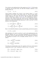
TABLE 13-1 Dimensions and Load Ratings for Deep Ball Bearing Series 6300. (From FAG Bearing Catalogue, with permission)
Number Dimensions Load ratings
Bearing Bearing Bearing Bearing Bearing Dynamic Static
of standard with one with two with one with two d D B r C C
0
design shield shields seal seals mm lbs lbs
6300 6300Z 6300.2Z 6300 RS 6300.2RS 10 35 11 1 1400 850
6301 6301Z 6301.2Z 6301 RS 6301.2RS 12 37 12 1.5 1700 1040
6302 6302Z 6302.2Z 6302 RS 6302.2RS 15 42 13 1.5 1930 1200
6303 6303Z 6303.2Z 6303 RS 6303.2RS 17 47 14 1.5 2320 1460
6304 6304Z 6304.2Z 6304 RS 6304.2RS 20 52 15 2 3000 1930
6305 6305Z 6305.2Z 6305 RS 6305.2RS 25 62 17 2 3800 2550
6306 6306Z 6306.2Z 6306 RS 6306.2RS 30 72 19 2 5000 3400
6307 6307Z 6307.2Z 6307 RS 6307.2RS 35 80 21 2.5 5700 4000
6308 6308Z 6308.2Z 6308 RS 6308.2RS 40 90 23 2.5 7350 5300
Copyright 2003 by Marcel Dekker, Inc. All Rights Reserved.
6309 6309Z 6309.2Z 6309 RS 6309.2RS 45 100 25 2.5 9150 6700
6310 6310Z 6310.2Z 6310 RS 6310.2RS 50 110 27 3 10600 8150
6311 6311Z 6311.2Z 55 120 29 3 12900 10000
6312 6312Z 6312.2Z 60 130 31 3.5 14000 10800
6313 6313Z 6313.2Z 65 140 33 3.5 16000 12500
6314 6314Z 6314.2Z 70 150 35 3.5 18000 14000
6315 75 160 37 3.5 19300 16300
6316 80 170 39 3.5 19600 16300
6317 85 180 41 4 21600 18600
6318 90 190 43 4 23200 20000
6319 95 200 45 4 24500 22400
6320 100 215 47 4 28500 27000
6321 105 225 49 4 30500 30000
6322 110 240 50 4 32500 32500
6324 120 260 55 4 36000 38000
6326 130 280 58 5 39000 43000
6328 140 300 62 5 44000 50000
6330 150 320 65 5 49000 60000
Copyright 2003 by Marcel Dekker, Inc. All Rights Reserved.
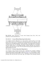
TABLE 13-2 Angular Contact Bearing of Series 909 a ¼25
, separable. (From FAG Bearing Catalogue, with permission)
Max. Load ratings
Dimensions fillet dynamic static
d D B C T a radius C C
0
Number inch inch lbs lbs
909001 .7503 2.0800 .5950 .6080 .7080 .65 .060 3250 2240
909002 1.1904 2.9630 .8700 .7700 1.1450 .91 .060 6100 4400
909003 .8128 2.4370 .6880 .7290 .8290 .73 .100 4550 3200
909004 1.2815 3.3750 .9640 .9330 1.3080 1.06 .010 8300 6300
909007 .9379 3.0300 .8440 .9310 1.0310 .96 .060 7500 5600
909008 1.4384 3.9300 1.0580 1.0950 1.4700 1.20 .100 11400 9150
909021 .6875 1.8750 .5630 .5630 .6880 .63 .060 3050 2040
909022 1.1250 2.5000 .8440 .6250 .9840 .75 .060 4150 2900
909023 .7503 2.2500 .6590 .6900 .7900 .73 .100 4500 3200
EQUIVALENT STATIC LOAD
Po ¼ F
r
when
F
a
F
r
1:3
Po ¼ 0:5F
r
þ 0:38 F
a
when
F
a
F
r
> 1:3
EQUIVALENT DYNAMIC LOAD
P ¼ F
r
when
F
a
F
r
0:68
P ¼ 0:41 F
r
þ 0:87 F
a
when
F
a
F
r
> 0:68
Copyright 2003 by Marcel Dekker, Inc. All Rights Reserved.
909024 1.3128 3.1496 .9170 .8510 1.2260 .98 .100 7350 5600
909025 .8440 2.2500 .6590 .6900 .7900 .75 .060 4300 3100
909026 1.4065 3.1496 .9170 .8510 1.2260 .98 .060 6550 5500
909027 .9379 2.8125 .8000 .8500 .9100 .91 .100 6300 4550
909028 1.5000 3.7500 1.0700 1.0150 1.4500 1.18 .100 9800 7650
909029 1.1250 3.1875 .8750 .9730 1.0730 1.02 .100 8300 6300
909030 1.6250 4.0625 1.1875 1.0950 1.5620 1.20 .100 11400 9150
909052 1.2815 2.9630 .8700 .7700 1.1450 .91 .060 6100 4400
909062 1.3750 2.9630 .8700 .7700 1.1450 .91 .060 6000 4550
909067 .7502 2.0800 .4690 .4690 .7080 .69 .040 3900 2750
909070 1.2500 2.6500 .7000 .5150 .8000 .81 .040 5300 3800
Copyright 2003 by Marcel Dekker, Inc. All Rights Reserved.