Bearing Design in Machinery Episode 2 Part 9 doc
Bạn đang xem bản rút gọn của tài liệu. Xem và tải ngay bản đầy đủ của tài liệu tại đây (251.27 KB, 18 trang )
wear and optimize the bearing life. In such cases, it is possible to have an optimal
design that operates with a full EHD fluid film. For this purpose, the designer can
calculate the minimum film thickness, h
min
, according to the equations discussed
in the following sections.
For optimal conditions, the minimum film thickness, h
min
, must be greater
than the surface roughness. The equivalent surface roughness at the contact, R
s
(RMS), is obtained from the roughness of the two individual surfaces in contact,
R
s1
and R
s2
, from the equation (see Hamroch, 1994)
R
s
¼ðR
2
s1
þ R
2
s2
Þ
1=2
ð12-38Þ
The surface roughness is measured by a profilometer, often referred to as stylus
measurement. Microscope devices are used when higher-precision measurements
are needed. The ratio L of the film thickness to the size of surface asperities, R
s
,
is:
L ¼
h
min
R
s
ð12-39Þ
For a full EHD lubrication of rolling bearings, L is usually between 3 and 5. The
desired ratio L is determined according to the expected level of vibrations and
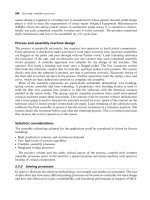
FIG. 12-20 Pressure wave and film thickness distribution in elastohydrodynamic
lubrication.
Copyright 2003 by Marcel Dekker, Inc. All Rights Reserved.
other disturbances in the machine. Although h
min
is very important for successful
bearing operation, calculation of h
0
is often required for determining the viscous
shear force, referred to as traction force, which is the resistance to relative sliding.
12.8 ELASTOHYDRODYNAMIC LUBRICATION
OF A LINE CON TACT
A theoretical line contact is formed between two cylinders, such as in a
cylindrical rolling bearing. For this case, Pan and Hamrock (1989) introduced
the following empirical equation for the minimum film thickness, h
min
:
h
min
R
x
¼
1:714
"
UU
0:694
r
ðaE
eq
Þ
0:568
"
WW
0:128
ð12-40Þ
Here, a is the viscosity–pressure coefficient. Although theoretical equations were
derived earlier, Eq. (12-40) is more accurate, because it is based on actual
measurements. The equation is a function of dimensionless terms. The advantage
in using dimensionless terms is that any system of units can be used, as long as
the units are consistent and result in dimensionless terms.
The dimensionless terms
"
UU
r
and
"
WW are the dimensionless rolling velocity
and load per unit of cylinder length, respectively. The dimensionless terms are
defined by:
"
UU
r
¼
m
0
E
eq
R
x
U
r
"
WW ¼
1
E
eq
R
x
L
W ð12-41Þ
Here, U
r
is the rolling velocity, Z
0
is the viscosity of the lubricant at atmospheric
pressure, W is the load on one rolling element, E
eq
is the equivalent modulus of
elasticity, and R
x
is an equivalent radius of contact in the x plane (direction of axis
of rotation of rolling element), as defined in Sec. 12.5.2.
Jones et al. (1975) measured the viscosity–pressure coefficient a ½m
2
=N
for various lubricants. The data is summarized in Table 12-1.
The rolling velocity
"
UU
r
in Eq. (12-41) is for pure rolling (no relative
sliding) (Eq. (12-34)). However, in many other problems, such as in gears and
cams, there is a combination of rolling and sliding. If the ratio of the rolling to the
sliding is x and U
s
is the sliding velocity, then the dimensionless rolling velocity
"
UU
r
used in Eq. (12-41) is replaced by
"
UU
r
¼
m
0
2E
eq
R
x
U
s
ð1 þxÞð12-42Þ
Equation (12-40) indicates that the viscosity and rolling speed have a more
significant effect on the minimum film thickness, h
min
, in comparison to the load
Copyright 2003 by Marcel Dekker, Inc. All Rights Reserved.
and its Poisson ratio is n ¼ 0:3. The bearing is lubricated by oil having an
absolute viscosity of m
0
¼ 0:01 N-s=m
2
at atmospheric pressure and bearing
operating temperature. The viscosity–pressure coefficient is a ¼ 2:2 Â
10
À8
m
2
=N.
Find the minimum elastohydrodynamic film thickness at the following
points:
a. At the contact of the rolling elements with the inner raceway
b. At the contact of the rolling elements with the outer raceway
Solution
The radii of the contacting curvatures are:
Roller radius: R
roller
¼ 0:01 m,
Outer ring raceway: R
outer raceway
¼ 0:08 m,
Inner ring raceway: R
inner raceway
¼ 0:06 m
The contact between the rolling elements and the inner raceway is convex, and
the equivalent contact curvature, R
x;in
, is derived according to the equation
1
R
x;in
¼
1
R
roller
þ
1
R
inner raceway
1
R
x;in
¼
1
0:01
þ
1
0:06
) R
eq;in
¼ 0:0085 m
However, the contact between the rolling elements and the outer raceway is
concave, and the equivalent contact curvature, R
x;out
, is derived according to the
equation
1
R
x;out
¼
1
R
roller
À
1
R
outer raceway
1
R
x;out
¼
1
0:01
À
1
0:08
; R
x;out
¼ 0:0114 m
If we assume that there is no radial clearance, then the maximum load on one
cylindrical rolling element can be calculated from the following formula:
W
max
¼
4W
shaft
n
r
¼
4 Â 11;000
14
¼ 3142 N
where n
r
is the number of rollers in the bearing. The shaft and the bearing are
made of identical material, so the equivalent modulus of elasticity is
E
eq
¼
E
1 À n
2
) E
eq
¼
2:05 Â10
11
1 À0:3
2
¼ 2:25 Â10
11
N=m
2
Copyright 2003 by Marcel Dekker, Inc. All Rights Reserved.
The dimensionless load on the inner race is
"
WW ¼
1
E
eq
R
x;in
L
W
max
¼
1
2:25 Â10
11
 0:0085 Â0:01
3142 ¼ 1:64 Â10
À4
In comparison, the dimensionless load on the outer race is
"
WW ¼
1
E
eq
R
x;out
L
W
max
¼
1
2:25 Â10
11
 0:0114 Â0:01
3142 ¼ 1:22 Â10
À4
Comparison of the inner and outer dimensionless loads indicates a higher
value for the inner contact. This results in higher contact stresses, including
maximum pressure, at the inner contact. The rolling velocity, U
r
, for a cylindrical
roller is calculated via Eq. (12-34).
U
r
¼
R
in
R
out
R
out
þ R
in
o
where the angular shaft speed, o, is equal to
o ¼
2pN
60
¼
2  p  5000
60
¼ 523 rad=s
Hence, the rolling speed is
U
r
¼
R
in
R
out
R
out
þ R
in
o ¼
0:06 Â0:08
0:06 þ0:08
523 ¼ 17:93 m=s
The dimensionless rolling velocity of the inner surface is
"
UU
r
¼
m
0
E
eq
R
x;in
U
r
¼
0:01
2:25 Â10
11
 0:0085
17:93 ¼ 9:375 Â10
À11
In comparison, the dimensionless rolling velocity at the outer ring race is
"
UU
r
¼
m
0
E
eq
R
x;out
U
r
¼
0:01
2:25 Â10
11
 0:0114
17:93 ¼ 6:99 Â10
À11
The elastohydrodynamic minimum film thickness is derived from Eq. (12.40) for
a fully lubricated ball bearing.
h
min
R
x
¼
1:714
"
UU
0:694
ðaE
eq
Þ
0:568
"
WW
0:128
The minimum oil film thickness at the contact with the inner raceway is
h
min
R
x;in
¼
1:714ð9:3 Â10
À11
Þ
0:694
ð2:2 Â 10
À8
 2:25 Â10
11
Þ
0:568
ð1:64 Â10
À4
Þ
0:128
h
min;in
¼ 0:609 mm
Copyright 2003 by Marcel Dekker, Inc. All Rights Reserved.
The minimum oil film thickness at the contact with the outer raceway is
h
min
R
x;out
¼
1:714ð6:99 Â 10
À11
Þ
0:694
ð2:2 Â 10
À8
 2:25 Â10
11
Þ
0:568
ð1:22 Â10
À4
Þ
0:128
h
min;out
¼ 0:695 mm
The minimum film thickness at the contact with the inner ring race is lower
because the equivalent radius of convex curvatures is lower. Therefore, it is
sufficient to calculate the minimum film thickness at the contact with the inner
ring race. However, for a rolling bearing operating at high speed, the centrifugal
force of the rolling element is added to the contact force at the contact with the
outer raceway. In such cases, h
min;out
may be lower than h
min;in
, and the EHD fluid
film should be calculated at the inner and outer ring races.
Example Problem 12-4
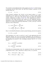
Elastohydrodynamic Fluid Film in a Cam and a Follower
A cam and a follower operate in a car engine as shown in Fig. 12-21. The cam
radius at the tip of the cam is R ¼ 20 mm, the distance of this radius center from
FIG. 12-21 Cam and follower.
Copyright 2003 by Marcel Dekker, Inc. All Rights Reserved.
the cam center of rotation is a ¼ 40 mm, and the width of the cam (effective
length of contact) is 10 mm. There is a maximum reaction force W ¼ 1200 N
between the cam and the follower when the follower reaches its maximum height.
The rotation speed of the cam is N ¼ 600 RPM. The cam and the follower are
made of steel. The steel modulus of elasticity is E ¼ 2:05 Â10
11
N=m
2
, and its
Poisson ratio n is 0.3. The contact between the cam and follower is fully
lubricated. The absolute viscosity at atmospheric pressure and engine tempera-
ture is m
0
¼ 0:01 N-s=m
2
, and the viscosity–pressure coefficient is a ¼
2:2 Â10
À8
m
2
=N.
Find the minimum oil film thickness at the contact between the cam and the
shaft.
Solution
The contact is between a plane and a curvature of radius R ¼ 20 mm at the tip of
the cam. In that case, the equivalent radius is R. The equation for the equivalent
modulus is
E
eq
¼
E
1 À n
2
¼
2:05 Â10
11
1 À 0:3
2
¼ 2:2 Â10
11
N=m
2
The dimensionless load becomes
"
WW ¼
1
E
eq
RL
W
max
¼
1
2:2 Â 10
11
 0:020 Â0:01
1200 ¼ 2:727 Â10
À5
The sliding velocity U is equal to the tangential velocity at the tip of the cam:
U ¼ oða þ RÞ
Here, o is equal to
o ¼
2pN
60
¼
2p600
60
¼ 62:83 rad=s
This problem is one of pure sliding, x ¼ 0, and the sliding velocity is
U
s
¼ð0:04 þ0:02Þ62:83 ¼ 3:76 m=s
For pure sliding, x ¼ 0, the dimensionless equivalent rolling velocity is
[Eq. (12-42)]
"
UU
r
¼
m
0
2E
eq
R
U
s
ð1 þ xÞ¼
0:01
2 Â 2:2 Â10
11
 0:02
3:76 ¼ 4:27 Â10
À12
Copyright 2003 by Marcel Dekker, Inc. All Rights Reserved.
For line contact and in the presence of sufficient lubricant, the elastohydro-
dynamic minimum film thickness is derived according to the equation
h
min
R
¼
1:714
"
UU
0:694
ðaE
eq
Þ
0:568
"
WW
0:128
The oil film thickness in the inner surface is
h
min
0:02
¼
1:714ð4:27 Â10
À12
Þ
0:694
ð2:2 Â10
À8
 2:22 Â10
11
Þ
0:568
ð2:727 Â10
À5
Þ
0:128
h
min
¼ 0:21 mm
12.9 ELASTOHYDRODYNAMIC LUBRICATION
OF BALL BEARINGS
Under load, the theoretical point contact between a rolling ball and raceways
becomes an elliptical contact area. The elliptical contact area has radii a and b,as
shown in Fig. 12-17.
In a similar way to the theoretical line contact, there is a minimum
elastohydrodynamic film thickness, h
min
, near the exit from a uniform film
thickness, h
0
. For hard surfaces, such as steel in rolling bearings, and sufficient
lubricant, Hamrock and Dowson (1977) obtained the following formula for the
minimum film thickness, h
min
:
h
min
R
x
¼ 3:63
"
UU
0:68
r
ðaE
eq
Þ
0:49
"
WW
0:073
ð1 Àe
À0:68k
Þð12-44Þ
Here, a is the viscosity–pressure coefficient and
"
UU
r
and
"
WW are dimensionless
velocity and load, respectively, defined by:
"
UU
r
¼
m
o
U
r
E
eq
R
x
and
"
WW ¼
W
E
eq
R
2
x
ð12-45Þ
Here, U
r
is the rolling velocity, m
0
is the viscosity of the lubricant at atmospheric
pressure and bearing operating temperature, W is the load on one rolling element,
and E
eq
is the equivalent modulus of elasticity.
The equations for the equivalent modulus of elasticity and equivalent
contact radius are used for calculating the Hertz stresses at a point contact.
These equations were discussed in Secs. 12.4 and 12.5. For convenience, these
equations are repeated here.
Recall that E
eq
is determined from equation
2
E
eq
¼
1 À n
2
1
E
1
þ
1 À n
2
2
E
2
Copyright 2003 by Marcel Dekker, Inc. All Rights Reserved.
Here, n is poisson’s ratio and E is the modulus of elasticity of the respective two
materials. For identical materials, the equation becomes
E
eq
¼
E
1 À n
2
The equivalent radius of curvature in the plane of rotation, R
x
, for the contact with
the inner ring race is
1
R
x
¼
1
R
1x
þ
1
R
2x
where R
1x
and R
2x
are as shown on the right-hand side of Fig. 12-18b for the
contact at the inner ring race and R
1x
¼ d=2, where d is the ball diameter.
On the left-hand side of Fig. 12-18b, the contact at the inner ring race is
concave, and the equivalent contact curvature radius in this plane is
1
R
y
¼
1
R
1y
À
1
R
2y
The radius ratio, a
r
(the ratio of the larger radius to the smaller radius, a
r
> 1) is
defined as
a
r
¼
R
y
R
x
The ellipticity parameter, k, is the ratio
k ¼
b
a
The parameter k can be estimated from
k % a
2=p
r
For hard surfaces, sufficient lubricant, and for pure rolling, Hamrock and
Dowson (1981) obtained the following formula for the central film thickness, h
c
(at the center of the fluid film):
h
c
R
x
¼ 2:69
"
UU
0:67
r
ðaE
eq
Þ
0:53
"
WW
0:067
ð1 À0:61e
À0:73k
Þð12-46Þ
This equation is useful for the calculation of the traction force (resistance to
relative sliding) where an EHD film is separating the surfaces.
For soft surfaces, such as rubber, the contact area is relatively large,
resulting in a lower contact pressure. In addition, the viscosity does not increase
as much as predicted by the preceding equations.
Copyright 2003 by Marcel Dekker, Inc. All Rights Reserved.
Example Problem 12-5
Find the minimum film thickness for a rolling contact of a deep-groove ball
bearing having the following dimensions: The bearing has 14 balls of diameter
d ¼ 19:04 mm. The radius of curvature of the inner-deep groove (in cross section
x-z on the left-hand side of Fig. 12-18b) is 9.9 mm. The inner race diameter, R
2x
(at the bottom of the deep groove), is d
i
¼ 76:5 mm (cross section y-z on the
right-hand side of Fig. 12-18b). The radial load on the bearing is W ¼ 10;500 N,
and the bearing speed is N ¼ 5000 RPM. The rolling elements and rings are
made of steel. The modulus of elasticity of the steel for rollers and rings is
E ¼ 2 Â 10
11
N=m
2
, and Poisson’s ratio is n ¼ 0:3. The properties of the
lubricant are: The absolute viscosity at ambient pressure and bearing operating
temperature is m
0
¼ 0:04 N-s=m
2
, and the viscosity–pressure coefficient is
a ¼ 2:3 Â10
À8
m
2
=N.
Solution
Referring to Fig. 12-18b, the radius of curvature in the y-z plane is
R
2x
¼ 38:25 mm and R
1x
¼
d
2
¼ 9:52 mm
Equivalent Radius for Inner Raceway Convex Contact in y-z Plane ðx Plane)
1
R
x
¼
1
R
1x
þ
1
R
2x
)
1
R
x
¼
1
9:52
þ
1
38:25
; R
x
¼ 7:62 mm
Equivalent Inner Radius in y Plane (Concave Contact)
The curvatures in this plane are: R
1y
¼ 9:52 mm and R
2y
¼ 9:9 mm. The
equivalent inner radius in the y plane is
1
R
y
¼
1
R
1y
À
1
R
2y
)
1
R
y
¼
1
9:52
À
1
9:9
; R
y
¼ 248:0mm
Equivalent Curvature of Inner Ring and Ball Contact
1
R
eq
¼
1
R
x
þ
1
R
y
)
1
R
eq
¼
1
7:62
þ
1
248
; R
eq
¼ 7:4mm
a
r
¼
R
y
R
x
¼ 32:55 and k ¼ a
2=p
r
¼ 32:54
2=p
¼ 9:18
Copyright 2003 by Marcel Dekker, Inc. All Rights Reserved.
The shaft and the bearing are made of identical steel, so the equivalent modulus
of elasticity is:
E
eq
¼
E
1 À n
2
) E
eq
¼
2 Â 10
11
1 À 0:3
2
¼ 2:2 Â10
11
N=m
2
For a ball bearing without radial clearance, the maximum load at the
contact of one rolling element can be estimated with the following equation:
W
max
%
5W
shaft
n
r
¼
5ð10;500Þ
14
¼ 3750 N
where n
r
¼ 14 is the number of balls in the bearing.
The angular velocity, o,is
o ¼
2pN
60
¼
2p5000
60
¼ 523:6 rad=s
The rolling speed is derived according to Eq. (12-34):
U
rolling
¼
R
in
R
out
2ðR
in
þ rÞ
o ¼
R
in
R
out
R
in
þ R
out
o
or
U
r
¼
R
2x
ðR
2x
þ dÞ
2R
2x
þ d
o
U
r
¼
38:25 Â 10
À3
ð38:25 Â10
À3
þ 19:05 Â10
À3
Þ
ð2 Â38:25 Â10
À3
Þþ19:04 Â10
À3
523:6 ¼ 12 m=s
The dimensionless rolling velocity at the inner ring race is
"
UU
r
¼
m
0
E
eq
R
x
U
r
¼
0:01
2:2 Â10
11
 0:00762
12 ¼ 7:17 Â 10
À11
The dimensionless load on the inner ring race is
"
WW ¼
1
E
eq
R
2
x
W
max
¼
1
2:2 Â10
11
 0:00762
2
3750 ¼ 2:94 Â10
À4
Finally, the oil film thickness between the inner race and the roller is
h
min
R
x
¼ 3:63
"
UU
0:68
r
ðaE
eq
Þ
0:49
"
WW
0:073
ð1 Àe
À0:68k
Þ)
h
min
0:00762
¼ 3:63
ð7:17 Â10
À11
Þ
0:68
ð2:3 Â10
À8
 2:2 Â10
11
Þ
0:49
ð2:94 Â 10
À4
Þ
0:073
Âð1 À e
À0:68Â9:18
Þ
Copyright 2003 by Marcel Dekker, Inc. All Rights Reserved.
Thus, at the inner ring race
h
min
¼ 0:412 mm
Example Problem 12-6
Centrifugal Force
The deep-groove ball bearing in Example Problem 12-5 is used in a high-speed
turbine where the average shaft speed is increased to N ¼ 30;000 RPM. The
radial bearing load is equal to that in Example Problem 12-5, W ¼ 10; 500 N.
The lubricant is also equivalent to that in Example Problem 12-5. The properties
of the lubricant are: The absolute viscosity at ambient pressure and bearing
operating temperature is m
0
¼ 0:04 N-s=m
2
, and the viscosity–pressure coeffi-
cient is a ¼ 2:3 Â10
À8
m
2
=N.
Consider the centrifugal force at this high-speed operation, and
a. find the maximum contact pressure at the inner and outer ring raceways.
b. calculate the minimum film thickness at the contact with the outer ring.
Solution
a. Maximum Contact Pressure
For the contact with the inner ring race, the maximum pressure and minimum
film thickness was calculated in Example Problems 12-2 and 12-5. In this
problem, the maximum pressure will be compared with that at the outer ring
race in the presence of a centrifugal force.
Contact with Outer Ring Race
The contact radii in the x plane (y-z plane) in Fig. 12-18b are:
R
2x
¼ 57:29 mm and R
1x
¼
d
2
¼ 9:52 mm
The equivalent radius for the outer raceway concave contact in the x plane (y-z
plane) is
1
R
x
¼
1
R
1x
À
1
R
2x
)
1
R
x
¼
1
9:52
À
1
57:29
; R
x
¼ 11:42 mm
Copyright 2003 by Marcel Dekker, Inc. All Rights Reserved.
Equivalent Outer Radius in y Plane
The curvatures in this plane are R
1y
¼ 9:52 mm and R
2y
¼ 9:9 mm. The
equivalent inner radius in the y (or x-z) plane is
1
R
y
¼
1
R
1y
À
1
R
2y
)
1
R
y
¼
1
9:52
À
1
9:9
; R
y
¼ 248:0mm
The equivalent radius of the outer ring and ball contact is
1
R
eq
¼
1
R
x
þ
1
R
y
)
1
R
eq
¼
1
11:42
þ
1
248
; R
eq
¼ 10:92 mm
a
r
¼
R
y
R
x
¼ 21:72
and
k ¼ a
2=p
r
¼ 21:72
2=p
¼ 7:1
It is also necessary to calculate
^
EE, which will be used to calculate the
ellipsoid radii. First q
a
will be determined
q
a
¼
p
2
À 1 ¼ 0:57
^
EE % 1 þ
q
a
a
r
) 1 þ
0:57
21:72
¼ 1:03
From Example Problem 12-5, the equivalent modulus of elasticity is
E
eq
¼ 2:2 Â10
11
N=m
2
The load on the bearing is divided unevenly between the rolling elements.
The approximate equation for zero bearing clearance is used. The maximum load,
W
max
, at a contact of one rolling element can be estimated by the following
equation:
W
max ðone ballÞ
%
5W
shaft
n
r
¼
5ð10;500Þ
14
¼ 3750 N
where n
r
¼ 14 is the number of balls in the bearing.
The total maximum load at the contact of one-roller and the outer raceway
is equal to the transmitted shaft load plus the centrifugal force generated.
The angular velocity o is
o ¼
2pN
60
¼
2  p  30;000
60
¼ 3141:59 rad=s
Copyright 2003 by Marcel Dekker, Inc. All Rights Reserved.
The angular velocity of the rolling-element center, point C, is given by
o
C
¼
R
in
R
in
þ R
out
o ¼
38:25
38:25 þ57:29
3141:59 ¼ 1257:75 rad=s
This angular velocity is used to calculate the centrifugal force, F
c
:
F
c
¼ m
r
R
c
o
2
C
The density of steel and the ball volume determine its mass:
m
r
¼
p
6
d
3
r ¼
p
6
 0:01904
3
 7800 ¼ 0:028 kg
After substituting these values in the equation for the centrifugal force, we obtain
F
c
¼ 0:028 Â0:04777 Â1257:75
2
¼ 2115:93 N
The maximum force is at the outer raceway. It is equal to the sum of the
transmitted shaft load and the centrifugal force:
W
max
¼ W
max;load
þ F
c
¼ 3750 þ2115:93 ¼ 5865: 93 N
The ellipsoid radii a and b can now be determined by substituting the values
already calculated:
a ¼
6
^
EEW
max
R
eq
pkE
eq
!
1=3
¼
6 Â 1:03 Â5865:93 Â 0:01092Þ
p  7:1 Â2:2  10
11
1=3
¼ 0:43 mm
b ¼
6k
2
^
EEW
max
R
eq
pE
eq
!
1=3
¼
6 Â 7:1
2
 1:03 Â5865:93 Â0:01092
p  2:2 Â10
11
1=3
¼ 3:07 mm
The maximum pressure at the outer contact is
p
max
¼
3
2
W
max
pab
¼
3
2
5865:93
p  0:43 Â3:07
¼ 2121:64 N=mm
2
¼ 2:12 GPa
The maximum pressure is very close to that at the inner ring contact,
p
max
¼ 2:17 GPa (see Example Problem 12.2).
Copyright 2003 by Marcel Dekker, Inc. All Rights Reserved.
b. Minimum Film Thickness at the Outer Ra ce Contact
Rolling occurs only in the x plane, so
U
r
¼
R
2x
ðR
2x
þ dÞ
2R
2x
þ d
o
U
r
¼
57:29 Â 10
À3
ð57:29 Â10
À3
þ 19:04 Â10
À3
Þ
ð2 Â57:29 Â10
À3
Þþ19:04 Â10
À3
3141:59 ¼ 102:81 m=s
The dimensionless velocity for the outer surface is
"
UU
r
¼
m
0
E
eq
R
x
U
r
¼
0:01
2:2 Â10
11
 0:01142
102:81 ¼ 4:09 Â10
À10
where U
r
is the rolling velocity of the ball on the race and o is the angular
velocity of the shaft, in rad=s. The dimensionless load on the outer race is
"
WW ¼
1
E
eq
R
2
x
W
max
¼
1
2:2 Â10
11
Âð0:01142Þ
2
 5865:93 ¼ 2:04 Â10
À4
Finally, the oil film thickness between the outside race and the ball is
h
min
R
x
¼ 3:63
"
UU
0:68
r
ðaE
eq
Þ
0:49
"
WW
0:073
ð1 Àe
À0:68k
Þ
h
min
0:01142
¼ 3:63
ð4:09 Â10
À10
Þ
0:68
ð2:3 Â10
À8
 2:2 Â10
11
Þ
0:49
ð2:04 Â 10
À4
Þ
0:073
Âð1 À e
À0:68Â7:1
Þ
h
min
¼ 2:06 mm
Example Problem 12-7
Ceramic Rolli ng Elements
For the high-speed turbine given in Example Problem 12-6, the bearing is
replaced by a deep-groove ball bearing with equivalent geometry. However, the
bearing is hybrid and the rolling elements are made of silicone nitride. The rings
are made of steel. The lubricant is also equivalent to that in Example Problems
12-5 and 12-6. The shaft speed is N ¼ 30;000 RPM. The radial bearing load is
equal to that in Example Problem 12-5, W ¼ 10;500 N.
a. Find the maximum pressure at the outer race contact
b. Compare the maximum pressure to that of all steel bearings in Example
Problem 12-6.
Copyright 2003 by Marcel Dekker, Inc. All Rights Reserved.
The properties of silicon nitride are:
E ¼ 3:14 GPa ð3:14 Â10
11
PaÞ; in comparison to steel; with E ¼ 2:00 GPa:
r ¼ 3200 kg=m
3
; in comparison to steel; with r ¼ 7800 kg=m
3
:
n ¼ 0:24; in comparison to steel; with n ¼ 0:3:
Solution
a. Maximum Pressure at the Outer Race
It is possible to decrease the centrifugal force by lowering the density of the
rolling elements. One important advantage of a hybrid bearing where the rolling
elements are made of silicone nitride (and the rings are made of steel) is that it
lowers the density of the rolling elements. However, we have to keep in mind that
the modulus of elasticity of silicone nitride is higher than that of steel, and this
may result in a higher maximum pressure. In this problem, the maximum pressure
is calculated and compared with those of a conventional steel bearing.
Radius of Curvature in the x Plane
R
2x
¼ 57:29 mm R
1x
¼
d
2
¼ 9:52 mm
The equivalent radius for the outer raceway contact in the x plane is
1
R
x
¼
1
R
1x
À
1
R
2x
)
1
R
x
¼
1
9:52
À
1
57:29
; R
x
¼ 11:42 mm
Equivalent Outer Radius in y Plane
The curvatures in this plane are R
1y
¼ 9:52 mm and R
2y
¼ 9:9 mm. The
equivalent inner radius in the y-z plane is
1
R
y
¼
1
R
1y
À
1
R
2y
)
1
R
y
¼
1
9:52
À
1
9:9
; R
y
¼ 248:0mm
The equivalent radius of the curvature of the outer ring and ball contact is
1
R
eq
¼
1
R
x
þ
1
R
y
)
1
R
eq
¼
1
11:42
þ
1
248
; R
eq
¼ 10:92 mm
a
r
¼
R
y
R
x
¼ 21:72
and
k ¼ a
2=p
r
¼ 21:72
2=p
¼ 7:1
Copyright 2003 by Marcel Dekker, Inc. All Rights Reserved.
It is also necessary to calculate
^
EE, which will be used to calculate the
ellipsoid radii. First, q
a
will be determined:
q
a
¼
p
2
À 1 ¼ 0:57
^
EE % 1 þ
q
a
a
r
) 1 þ
0:57
21:72
¼ 1:03
For a hybrid bearing, we must consider the equivalent modulus of elasticity of
two different materials (steel and silicon nitride), given by
2
E
eq
¼
1 À n
2
21
E
1
þ
1 À n
2
2
E
2
)
2
E
eq
¼
1 Àð0:24Þ
2
3:14 Â10
11
þ
1 Àð0:3Þ
2
2:0 Â10
11
) E
eq
¼ 2:65 Â10
11
Pa
The maximum load transmitted by one rolling element at the contact with the ring
(assuming zero clearance) is estimated by the following equation:
W
max
%
5W
shaft
n
r
¼
5ð10;500Þ
14
¼ 3750 N
The number of balls in the bearing is n
r
¼ 14.
The total maximum load at the contact of one roller and the outer raceway
is equal to the transmitted shaft load plus the centrifugal force generated. The
angular velocity o is equal to
o ¼
2pN
60
¼
2p30;000
60
¼ 3141:59 rad=s
The angular velocity of the rolling element center, point C, is given by
o
C
¼
R
in
R
in
þ R
out
o ¼
38:25
38:25 þ57:29
3141:59 ¼ 1257:75 rad=s
This angular velocity is used to calculate the centrifugal force, F
c
:
F
c
¼ m
r
ðR
i
þ rÞo
2
C
The density (silicon nitride) and volume determine the mass of the ball:
m
r
¼
p
6
d
3
r )
p
6
 0:01904
3
 3200 ¼ 0:012 kg
Substituting these values in the equation for centrifugal force we obtain
F
c
¼ 0:012 Â0:04777 Â1257:75
2
¼ 906:76 N
Copyright 2003 by Marcel Dekker, Inc. All Rights Reserved.
Therefore, the maximum force occurs at the outer raceway. It is equal to the sum
of the shaft load and the centrifugal force:
W
max
¼ W
max;load
þ F
c
) 3750 þ906:76 ¼ 4656:76 N
In comparison, w
max
¼ 5866 N , for all steel-bearing and identical conditions
(Example Problem 12-6).
The ellipsoid radii a and b can now be determined by substitution of the
values already calculated:
a ¼
6
^
EEW
max
R
eq
pkE
eq
!
1=3
¼
6 Â 1:03 Â4656:76 Â 0:01092
p  7:1 Â2:65  10
11
1=3
¼ 0:38 mm
b ¼
6k
2
^
EEW
max
R
eq
pE
eq
!
1=3
¼
6 Â 7:1
2
 1:03 Â4656:76 Â0:01092
p  2:65 Â10
11
1=3
¼ 2:67 mm
The maximum pressure at the outer race contact is
p
max
¼
3
2
W
max
pab
¼
3
2
4656:76
p  0:38 Â2:67
¼ 2190 N=mm
2
¼ 2:19 GPa
b. Comparison with All-Steel Bearing
The bearing made of steel has a maximum pressure of 2.12 GPa on the outer
raceway, while the hybrid bearing has a maximum pressure of 2.19 GPa. By using
rollers made of silicon nitride, it is possible to reduce the centrifugal force by
lowering the density of the rolling element. Although the centrifugal force is
reduced, the modulus of elasticity of the ceramic rolling element is higher. The
combination of these two factors results in a slight increase in pressure on the
outer raceway, which was unexpected. In conclusion, for this specific application
there is no reduction in the maximum pressure by replacing the steel with silicon
nitride ceramic rolling elements.
12.10 FORCE COMPONENTS IN AN ANGULAR
CONTACT BEARING
In an angular contact bearing, the resultant contact forces of a ball with the inner
and outer ring races, W
i
and W
o
, are shown in Fig. 12-22. At low speed, the
centrifugal forces of the rolling element are small and can be neglected in
comparison to the external load. In that case, the contact angle of the inner ring,
a
i
is equal to the contact angle of the outer ring, a
o
; see Fig. 12-22. However, at
high speed the centrifugal forces are significant and should be considered. In that
Copyright 2003 by Marcel Dekker, Inc. All Rights Reserved.
The two unknowns, the contact angle with the outer ring, a
o
, and the reaction
force, W
o
, are solved from the two equations of balance of forces on a rolling
element. The balance of forces in the x (horizontal) direction is
S F
x
¼ 0
W
oa
¼ W
ia
ð12-48Þ
In the y (vertical) direction, the balance of forces is
S F
y
¼ 0
W
ir
þ F
c
¼ W
or
ð12-49Þ
Example Problem 12-8
An angular contact ball bearing has a contact angle with the inner ring of
a
i
¼ 40
. The thrust load is 2400 N divided exactly evenly on 12 balls (thrust load
of 200 N on each ball). The ball has a diameter of d
r
¼ 14 mm. The shaft speed is
N ¼ 30;000 RPM. The diameter of the outer race at the contact point with the
balls is 78 mm, and the radius of the race groove, in an axial cross section, is
8 mm. The balls and rings are made of steel having the following properties:
E ¼ 2 Â 10
11
N=m
2
n ¼ 0:3
r ¼ 7870 kg=m
3
Find the contact angle a
o
and the contact force with the inner and outer
rings.
Solution
Given:
a
i
¼ 40
N ¼ 30;000 RPM
W
a
¼ 200 N
d
r
¼ 14 mm ¼ 0:014 m
R
out
¼ 39 mm ¼ 0:039 m
R
in
¼ 25 mm ¼ 0:025 m
R
cðball centerÞ
¼ 32 mm ¼ 0:032 m
Copyright 2003 by Marcel Dekker, Inc. All Rights Reserved.