Advanced Vehicle Technology Episode 3 Part 1 ppt
Bạn đang xem bản rút gọn của tài liệu. Xem và tải ngay bản đầy đủ của tài liệu tại đây (295.04 KB, 20 trang )
(Fig. 10.45). On either side of the torque tube
is a trailing arm which locates the axle and also
transmits the driving and braking thrust between
the wheels and body. Coil springs are mounted
vertically between the axle and body structure,
their only function being to give elastic support to
the vehicle's laden weight. Lateral body to axle
alignment is controlled by a transverse Watt
linkage. The linkage consists of an equalizing arm
pivoting centrally on the axle casing with upper and
lower horizontal link arms anchored at their outer
ends by rubber pin joints to the body structure.
Thus when the springs deflect or the body rolls,
the link arms will swing about their outer body
location centres causing the equalizing arm to
tilt and so restrain any relative lateral body to
axle movement without hindering body vertical
displacement.
With the transversely located Watt linkage, the
body roll centre will be in the same position as the
equalizing arm pivot centre. The inherent disad-
vantages of this layout are still the high amount
of unsprung weight and the additional linkage
required for axle location.
10.7.2 Non-drive rear suspension
The non-drive (dead) rear axle does not have the
drawback of a large unsprung weight and it has the
merit of maintaining both wheels parallel at all
times. There is still the unwanted interconnection
between the wheels so that when one wheel is raised
off the ground the axle tilts and both wheels
become cambered.
The basic function of a rear non-drive rear sus-
pension linkage is to provide a vertical up and
down motion of the axle relative to the body as
the springs deflect and at the same time prevent
longitudinal and lateral axle misalignment due to
braking thrust, crosswinds or centrifugal side force.
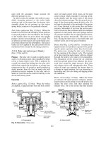
Five link coil spring leading and trailing arm Watt
linkage and Panhard rod non-drive axle rear suspen-
sion (Fig. 10.46) One successful rigid axle beam
and coil spring rear suspension linkage has incorp-
orated a Watt linkage parallel to each wheel to
control the axle in the fore and aft direction (Fig.
10.46). A transversely located Panhard rod con-
nected between the axle and body structure is also
included to restrict lateral body movement when it
is subjected to side thrust.
Trailing arms with central longitudinal wishbone
and anti-roll tube non-drive axle rear suspension
(Fig. 10.47) A rectangular hollow sectioned axle
beam spans the two wheels and on either side are
mounted a pair of coil springs. A left and right
hand trailing arm links the axle beam to the body
structure via rubber bushed pivot pins located at
both ends of the arms at axle level (Fig. 10.47). To
locate the axle beam laterally and to prevent it
rotating when braking, an upper longitudinal wish-
bone arm (`A' arm) is mounted centrally between
the axle and body structure. The `A' arm maintains
the axle beam spring mounting upright as the
spring deflects in either bump or rebound, thus
preventing the helical coil springs bowing. It also
keeps the axle beam aligned laterally when the
body is subjected to any side forces caused by
sloping roads, crosswinds and centrifugal force.
Situated just forward of the axle beam is a trans-
verse anti-roll tube welded to the inside of each
trailing arm. When body roll occurs while the car
is cornering, the inner and outer trailing arms will
tend to lift and dip respectively. This results in both
trailing arms twisting along their length. Therefore
the anti-roll tube, which is at right angles to the
arms, will be subjected to a torque which will be
resisted by the tube's torsional stiffness. This tor-
sional resistance thus contributes to the coil spring
Fig. 10.46 Five link coil spring leading and trailing arm Watt linkage and Panhard rod dead axle rear suspension
392
roll stiffness and increases in proportion to the
angle of roll. With this type of suspension the
unsprung weight is minimized and the wheels
remain perpendicular to the ground under both
laden weight and body roll changes.
Trailing arm and torsion bar spring with non-drive
axle rear suspension (Fig. 10.48) The coil springs
normally intrude into the space which would be
available for passengers or luggage, therefore tor-
sion bar springs transversely installed in line with
the pivots of the two trailing arms provide a much
more compact form of suspension springing
(Fig. 10.48). During roll of the body, and also
when the wheels on each side are deflected
unequally, the axle beam is designed to be loaded
torsionally, to increase the torsional flexibility and
to reduce the stress in the material. The axle tube
which forms the beam is split underneath along its
full length. This acts as an anti-roll bar or stabilizer
when the springs are unevenly deflected. The pivot
for each trailing arm is comprised of a pair of
rubber bushes pressed into each end of a transverse
tube which forms a cross-member between the two
longitudinal members of the floor structure of the
body. The inner surface of the rubber bush is
bonded to a hexagonal steel sleeve which is
mounted on a boss welded to the outside of the
trailing arm. In the centre of the trailing arm boss is
a hexagonal hole which receives the similar shaped
end of the torsion bar. To prevent relative move-
ment between the male and female joint made
between the boss and torsion bar, a bolt locked
by a nut in a tapped radial hole in the boss presses
against one of the flats on the torsion bar.
One torsion bar spring serves both suspension
arms so that a hexagon is forged mid-way between
the ends of the bar. It registers in a hexagonal hole
formed in the steel collar inserted in and spot
welded to the transverse tube that houses the tor-
sion bar spring. Again the torsion bar and collar
are secured by a radial bolt locked by a nut.
In the static laden position a typical total angular
deflection of the spring would be 20
and at full
bump about 35
. To give lateral support for the
very flexible trailing arms a Panhard rod is diag-
onally positioned between the trailing arms so that
it is anchored at one end to the axle beam and at the
other end to the torsion bar tubular casing. All
braking torque reaction is absorbed by both trail-
ing arms.
Trailing arm and coil spring twist axle beam non-
drive axle rear suspension (Fig. 10.49(a, b and c))
The pivoting trailing arms are joined together at
their free ends by an axle beam comprised of a
tubular torsion bar enclosed by a inverted `U'
channel steel section, the ends of the beam being
Fig. 10.47 Trailing arm coil spring with central longitudinal wishbone and anti-roll tube dead axle suspension
Fig. 10.48 Trailing arm and torsion bar spring with dead
axle rear suspension
393
butt welded to the insides of the both trailing arms
(Fig. 10.49(a, b and c)).
When both wheels are deflected an equal
amount, caused by increased laden weight only,
the coil springs are compressed (Fig. 10.49(a)). If
one wheel should be raised more than the other, its
corresponding trailing arm rotates about its pivot
causing the axle beam to distort to accommodate
the difference in angular rotation of both arms
(Fig. 10.49(b)). Consequently the twisted axle
beam tube and outer case section will transfer the
torsional load from the deflected trailing arm to the
opposite arm. This will also cause the undeflected
arm to rotate to some degree, with the result that
the total body sway is reduced.
During cornering when the body rolls, the side of
the body nearest the turn will lift and the opposite
side will dip nearer to the ground (Fig. 10.49(c)).
Thus the inner trailing arm will be compelled to
rotate clockwise, whereas the outer trailing arm
rotates in the opposite direction anticlockwise. As
a result of this torsional wind-up of the axle beam,
the outer wheel and trailing arm will tend to pre-
vent the inner trailing arm from rotating and lifting
the body nearest the turn. Hence the body roll
tendency will be stabilized to some extent when
cornering.
With this axle arrangement much softer coil
springs can be used to oppose equal spring deflec-
tion when driving in the straight ahead direction
than could otherwise be employed if there were no
transverse interconnecting beam.
Strut and link non-drive rear independent suspension
(Fig. 10.50) With this suspension the wheel hub
carrier's up and down motion is guided by the
strut's sliding action which takes place between its
piston and cylinder. The piston rod is anchored by
a rubber pivot to the body structure and the cylin-
der member of the strut is rigidly attached to the
wheel hub carrier (Fig. 10.50). A transverse link
(wishbone arm) connects the lower part of the
hub carrier to the body, thereby constraining all
lateral movement between the wheels and body.
The swing link arm and sliding strut member's
individual movements combine in such a way that
the hub carrier's vertical motion between bump
and rebound produces very little change to the
static wheel camber, either when the laden weight
alters or when cornering forces cause the body to
roll.
Braking fore and aft inertia forces are transmitted
from the body to the hub carrier and wheel by
trailing radius arms which are anchored at their
Fig. 10.49 (a±c) Trailing arm twist axle beam rear
suspension
394
forward ends by rubber pin joints to the body under-
structure. Owing to the trailing radius arms being
linked between the body and the underside of each
wheel hub carrier, deflection of the coil springs will
cause a small variation in wheel toe-in to occur
between the extremes in vertical movement.
The positioning of the body roll centre height
will be largely influenced by the inclination of the
swing arm relative to the horizontal; the slope of
these transverse arms are usually therefore chosen
so that the roll centre height is just above ground
level.
10.7.3 Rear wheel drive suspension
Swing arm rear wheel drive independent suspension
(Fig. 10.51) This suspension normally takes the
form of a pair of triangular transverse (`A' arm)
swing arm members hinging on inboard pivot
joints situated on either side of the final drive
with their axes parallel to the car's centre line
(Fig. 10.51). Coil springs are mounted vertically
on top of the swing arm members near the outer
ends. The wheels are supported on drive hubs
mounted on ball or tapered roller bearings located
within the swing arm frame.
Each drive shaft has only one universal joint
mounted inboard with its centre aligned with that
of the swing arm pivot axes. If the universal joints
and swing arm pivot axes are slightly offset (above
and below in diagram), the universal joints must
permit a certain amount of sliding action to take
place to compensate for any changes in drive shaft
length as the spring deflects. Usually the outer end of
the drive shaft forms part of the stub axle wheel hub.
Any increase in static vehicle weight causes the
swing arms to dip so that the wheels which were
initially perpendicular to the road now become
negatively cambered, that is, both wheels lean
towards the body at the top. Consequently, when
the body rolls during cornering conditions, the
inner and outer wheels relative to the turn become
cambered negatively and positively respectively;
they both lean towards the centre of rotation.
With a change in static vehicle weight both swing
arms pivot and dip an equal amount which reduces
the wheel track width. Similarly, if the body rolls
the inner swing arm pivot centre rises and the outer
swing arm pivot drops, so in fact both the swing
arm pivots tend to rotate about their roll centres
thus reducing the width of the wheel track again.
Both wheels at all times will remain parallel as there
is no change in wheel toe-in or -out.
Low pivot split axle coil spring rear wheel drive
independent suspension (Fig. 10.52) The conven-
tional transverse swing arm suspension suffered
from three major limitations:
Fig. 10.50 Strut and link non-drive independent rear suspension
Fig. 10.51 Transverse swing arm coil spring rear wheel drive independent suspension
395
1 The swing arms were comparatively short
because the pivot had to be mounted on either
side of the final drive housing; it therefore caused
a relatively large change in wheel camber as the
car's laden weight increased or when wheel
bounce occurred.
2 Due to the projection lines extending from the
tyre to ground centre contact to and beyond the
swing arm pivot centres, the body roll centre
with this type of suspension was high.
3 There was a tendency when cornering for the
short swing arms to become jacked up and with
the load concentrated on the outside, the highly
positively cambered wheel reduced its ability to
hold the road so that the rear end of the car was
subjected to lateral breakaway.
To overcome the shortcomings of the relatively
large change in wheel camber and the very high roll
centre height, the low pivot split axle suspension was
developed.
With this modified swing axle arrangement the
axle is split into two, with the adjacent half-axles
hinged on a common pivot axis below the final
drive housing (Fig. 10.52). A vertical strut supports
the final drive assembly; at its upper end it is
mounted on rubber discs which bear against the
rear cross-member and at its lower end it is
anchored to a pin joint situated on the hinged side
of the final drive pinion housing. The left hand
half-axle casing houses a drive shaft, crownwheel
and differential unit. A single universal joint is
positioned inside the casing so that it aligns with
the pivot axis of the axles. The right hand half-axle
houses its own drive shaft and a rubber boot pro-
tects the final drive assembly from outside contam-
ination, such as dirt and water. A horizontal arm
forms a link between the pivot axis and body struc-
ture and controls any lateral movement of the body
relative to the axles. Fore and aft support for each
half-axle is given by trailing radius arms which also
carry the vertically positioned coil springs. The
body roll centre thus becomes the pivot axis for
the two half-axles which is considerably lower
than for the conventional double pivot short
swing arm suspension.
Trailing arm rear wheel drive independent suspension
(Fig. 10.53) The independent trailing arm suspen-
sion has both left and right hand arms hinged on
an axis at right angles to the vehicle centre line
(Fig. 10.53). Each arm, which is generally semi-
triangular shaped, is attached to two widely spaced
pivot points mounted on the car's rear subframe.
Thus the trailing arms are able to transfer the drive
thrust from the wheel and axle to the body struc-
ture, absorb both drive and braking torque reac-
tions and to restrain transverse body movement
when the vehicle is subjected to lateral forces. The
Fig. 10.52 Low pivot split axle coil spring rear wheel drive suspension
Fig. 10.53 Trailing arm coil spring rear wheel drive independent suspension
396
rear ends of each arm support a live wheel hub, the
drive being transmitted from the final drive to each
wheel via drive shafts and inner and outer universal
joints to accommodate the angular deflection of
the trailing arms. The inner joints also incorporate
a sliding joint to permit the effective length of the
drive shafts to vary as the trailing arms articulate
between bump and rebound.
When the springs deflect due to a change in laden
weight, both wheels remain perpendicular to the
ground. When the body rolls on a bend, the inner
wheel becomes negatively cambered and the out-
side wheel positively cambered; both wheels lean
away from the turn. Spring deflection, caused by
either an increase in laden weight or wheel impact,
does not alter the wheel track toe-in or -out or the
wheel track width, but body roll will cause the
wheel track to widen slightly.
Semi-trailing arm rear wheel drive independent sus-
pension (Fig. 10.54) With the semi-trailing arm
suspension each arm pivots on an axis which is
inclined (skewed) to something like 50 to 70 degrees
to the car's centre line axis (Fig. 10.54). The pivot
axes of these arms are neither transverse nor longi-
tudinally located but they do lie on an axis which is
nearer the trailing arm pivot axis (which is at right
angles to the car's centre line axis). Consequently
the arms are classified as semi-trailing.
Swivelling of these semi-trailing arms is therefore
neither true transverse or true trailing but is a
combination of both. The proportion of each
movement of the semi-trailing arm will therefore
depend upon its pivot axis inclination relative to
the car's centre line. With body roll the transverse
swing arm produces positive camber on the inside
wheel and negative camber on the outer one (both
wheels lean inwards when the body rolls), whereas
with a trailing arm negative camber is produced on
the inside wheel and positive camber on the outer
one (both wheels lean outwards with body roll).
Skewing the pivot axis of the semi-trailing arm
suspension partially neutralizes the inherent ten-
dencies when cornering for the transverse swing
arm wheels to lean towards the turn and for the
trailing arm wheels to lean away from the turn.
Therefore the wheels remain approximately per-
pendicular to the ground when the car is subjected
to body roll.
Because of the relatively long effective swing arm
length of the semi-trailing arm, only a negligible
change to negative camber on bump and positive
camber on rebound occurs when both arms deflect
together. However, there is a small amount of
wheel toe-in produced on both inner and outer
wheels for both bump and rebound arm move-
ment, due to the trailing arm swing action pulling
the wheel forward as it deflects and at the same
time the transverse arm swing action tilting the
wheel laterally.
By selecting an appropriate semi-trailing arm
pivot axis inclination, an effective swing arm length
can be produced to give a roll centre height some-
where between the ground and the pivot axis of the
arms. By this method the slip angles generated by
the rear tyres can be adjusted to match the under-
steer cornering characteristics required.
Transverse double link arm rear wheel drive indepen-
dent suspension (Figs 10.55 and 10.56) This class
of suspension may take the form of an upper and
lower wishbone arm linking the wheel hub carrier
to the body structure via pivot joints provided at
either end of the arms. Drive shafts transfer torque
from the sprung final drive unit to the wheel hub
through universal joints located at the inner and
outer ends of the shafts. Driving and braking thrust
and torque reaction is transferred through the wide
set wishbone pivot joints. One form of transverse
double link rear wheel drive independent suspen-
sion uses an inverted semi-elliptic spring for its
upper arm (Fig. 10.55).
A double wishbone layout has an important
advantage over the swing axle and trailing arm
arrangements in that the desired changes of wheel
camber, relative to motions of the suspension, can
Fig. 10.54 Semi-trailing arm coil spring rear wheel drive independent suspension
397
be obtained more readily. With swing axles, cam-
ber changes tend to be too great, and the roll centre
too high. Wheels located by trailing arms assume
the inclination of the body when it rolls, thereby
reducing the cornering forces that the tyres pro-
duce. Generally, transverse double link arm sus-
pensions are designed to ensure that, when
cornering, the outer wheel should remain as close
to the vertical as possible.
A modified version (Fig. 10.56) of the transverse
double link suspension comprises a lower trans-
verse forked tubular arm which serves mainly to
locate the wheel transversely; longitudinal location
is provided by a trailing radius arm which is a steel
pressing connecting the outer end of the tubular
arm to the body structure. With this design the
upper transverse link arm has been dispensed
with, and a fixed length drive shaft with Hooke's
universal joints at each end now performs the task
of controlling the wheel hub carrier alignment as
the spring deflects. Compact twin helical coil
springs are anchored on both sides of the lower
tubular forked arms with telescopic dampers posi-
tioned in the middle of each spring.
DeDion axle rear wheel drive suspension (Figs 10.57
and 10.58) The DeDion axle is a tube (sometimes
rectangular) sectioned axle beam with cranked (bent)
ends which are rigidly attached on either side to each
wheel hub. This permits the beam to clear the final
drive assembly which does not form part of the axle
beam but is mounted independently on the underside
of the body structure (Figs 10.57 and 10.58).
To attain good ride characteristics the usual slid-
ing couplings at the drive shaft to the wheels are
dispensed with in this design since when transmit-
ting drive or braking torque, such couplings
generate considerable frictional resistance which
opposes the sliding action. A sliding joint is pro-
vided in the axle tube to permit wheel track varia-
tion during suspension movement (Fig. 10.57).
Axle lateral location is therefore controlled by the
drive shafts which are permitted to swing about the
universal joint centres but are prevented from
extending or contracting in length. Fore and aft
axle location is effected by two Watt linkages.
These comprise two lower trailing fabricated
pressed steel arms, which also serve as the lower
seats for the coil springs. Their rear ends are carried
on pivots below the hub carriers. The other parts of
the Watt linkage consist of two rearward extending
tubular arms, each attached to a pivot above the
hub carrier. The upper and lower unequal length
link arm pivot centres on the body structure are
arranged in such a way that the axle has a true
vertical movement as the spring deflects so that
there are no roll steer effects. When the body rolls
Fig. 10.55 Transverse swing arm and inverted semi-
elliptic spring rear wheel drive independent suspension
Fig. 10.56 Transverse swing arm and double universal
joint load bearing drive shaft rear independent suspension
Fig. 10.57 DeDion axle with leading and trailing arm Watt linkage rear suspension
398
one hub carrier tends to rotate relative to the other,
which is permitted by the sliding joint in the axle
tube. The inner and outer sliding joints of the axle
tube are supported on two widely spaced bronze
bushes. The internal space between the inner and
outer axle tube is filled about two thirds full of oil
and lip seals placed on the outboard end of each
bearing bush prevents seepage of oil. A rubber boot
positioned over the axle sliding joint prevents dirt
and water entering between the inner and outer
tube members.
A DeDion axle layout reduces the unsprung sus-
pension weight for a rear wheel drive car, particu-
larly if the brakes are situated inboard. It keeps both
road wheels parallel to each other under all driving
conditions and transfers the driving and braking
torque reactions directly to the body structure
instead of by the conventional live axle route by
way of the axle casing and semi-elliptic springs or
torque rods to the body. The wheels do not remain
perpendicular to the ground when only one wheel
lifts as it passes over a hump or dip in the road. The
body roll centre is somewhere near the mid-height
position of the wheel hub carrier upper and lower
link arm pivot points; a typical roll centre height
from the ground would be 316 mm.
An alternative DeDion axle layout forms a tri-
angle with the two diagonal radius arms which are
rigidly attached to it (Fig. 10.58). The apex where
the two radius arms meet is ahead of the axle and is
pivoted by a ball joint to the body cross-member so
that the driving and braking thrust is transferred
from the axle to the body structure via the diagonal
arms and single pivot. A transverse Watt linkage
mounted parallel and to the rear of the axle beam
controls lateral body movement relative to the axle.
Therefore the body is constrained to roll on an axis
which passes between the front pivot supporting
the radius arms and the central Watt linkage
pivot to the rear of the axle.
The sprung final drive which is mounted on the
underside of the rear axle arch transmits torque to
the unsprung wheels by way of the drive shaft and
their inner and outer universal joints. The effective
length of the drive shaft is permitted to vary as the
suspension deflects by adopting splined couplings
or pot type joints for both inner universal joints.
10.8 Suspension design consideration
10.8.1 Suspension compliance steer
(Fig. 10.59(a and b))
Rubber bush type joints act as the intermediates
between pivoting suspension members and the
body to reduce the transmission of road noise from
the tyres to the body. The size, shape and rubber
hardness are selected to minimize noise vibration
and ride hardness by operating in a state of com-
pressive or torsional distortion.
If the rubber joints are subjected to any abnor-
mal loads, particularly when the suspension pivots
are being articulated, the theoretical geometry of
the swing members may be altered so that wheel
track misalignment may occur.
The centrifugal force when cornering can pro-
duce lateral accelerations of 0.7 to 8.0 g which is
sufficient to compress and distort the rubber and
move the central pin off-centre to the outer hole
which supports the rubber bush.
With transverse or semi-trailing arms suspension
(Fig. 10.59(a)) the application of the brakes retards
the rotation of the wheels so that they lag behind
the inertia of the body mass which is still trying to
Fig. 10.58 DeDion tube with diagonal radius arms and Watt transverse linkage rear suspension
399
thrust itself forward. Consequently the opposing
forces between the body and suspension arms will
distort the rubber joint, causing the suspension
arms to swing backwards and therefore make the
wheel track toe outwards.
The change in the wheel track alignment caused
by the elastic deflection of the suspension rubber
pivot joints is known as suspension compliance steer
since it introduces an element of self-steer to vehicle.
Compliance steer is particularly noticeable on
cornering if the brakes are being applied since the
heavily loaded outside rear wheel and suspension is
then subjected to both lateral forces and fore and
aft force which cause an abnormally large amount
of rubber joint distortion and wheel toe-out
(Fig. 10.59(a)), with the result that the steering
will develop an unstable oversteer tendency.
A unique approach to compliance steer is
obtained with the Weissuch axle used on some
Porsche cars (Fig. 10.59(b)). This rear transverse
upper and lower double arm suspension has an
additional lower two piece link arm which takes
the reaction for both the accelerating and deceler-
ating forces of the car. The lower suspension links
consist of a trailing tubular steel member which
carries the wheel stub axle and the transverse steel
plate arm. The trailing member has its front end
pivoted to a short torque arm which is anchored to
the body by a rubber bush and pin joint pivoted at
about 30
to the longitudinal car axis. When the car
decelerates the drag force pulls on the rubber bush
pin joint (Fig. 10.59(b)) so that the short torque
arm is deflected backward. As a result, the trans-
verse steel plate arm distorts towards the rear and
the front end of the trailing tubular member sup-
porting the wheel is drawn towards the body, thus
causing the wheel to toe-in. Conversely, when the
car is accelerated the wheel tends to toe-out, but
this is compensated by the static (initial) toe-in
which is enough to prevent them toeing-out under
driven conditions. The general outcome of the
lower transverse and trailing link arm deflection
is that when cornering the more heavily loaded
outside wheel will toe-in and therefore counteract
Fig. 10.59 (a and b) Semi-trailing suspension compliance steer
400
some of the front wheel steer, thus producing
a degree of understeer.
10.8.2 Suspension roll steer
(Fig. 10.60(a, b and c))
When a vehicle is cornering the body tilts and
therefore produces a change in its ground height
between the inside and outside wheels. By careful
design, the suspension geometry can be made to
alter the tracking direction of the vehicle. This
self-steer effect is not usually adopted on the
front suspension as this may interfere with steer-
ing geometry but it is commonly used for the rear
suspension to increase or decrease the vehicle's
turning ability in proportion to the centrifugal
side force caused by cornering. Because it affects
the steering handling characteristics when corner-
ing it is known as roll oversteer and roll understeer
respectively.
Roll steer can be designed to cancel out large
changes in tyre slip angles when cornering, particu-
larly for the more heavily loaded outer rear wheel
since the slip angle also increases roughly in pro-
portion to the magnitude of the side force.
The amount of side force created on the front or
rear wheels is in proportion to the load distribution
on the front and rear wheels. If the car is lightly
laden at the front the rear wheels generate a greater
slip angle than at the front, thus producing an
oversteer tendency. When the front is heavily
loaded, the front end has a greater slip angle and
so promotes an understeer response.
The object of roll steer on the rear wheels is for
the suspension geometry to alter in such a way that
Fig. 10.60 (a±c) Semi-trailing suspension roll steer
401
the rear wheels steer the back end of the vehicle
either outwards or inwards to compensate for the
deviation in directional steer caused by changes in
tyre slip angle.
A good example which illustrates suspension roll
steer is with the semi-trailing arm steer rear suspen-
sion (Fig. 10.60(a, b and c)). If the body tilts when
the vehicle corners the arms swing about their pivots
so that the wheel axle attached to their free ends
scribes circular arcs as they deflect up or down.
When the body rolls with the trailing arms set
horizontally in their static position (Fig. 10.60(a)),
the outer wheel and arm swings upwards towards
the body whereas the inner wheel and arm rotates
downwards and away from the body.
The consequence of the movement of the arms is
that both axles move forward a distance x but
because the axles of both trailing arms pivot at an
inclined angle to the central axis of the vehicle the
axis of end wheel axle will be slightly skewed
inward so that both wheels now toe-in.
If the static position of the trailing arms were
now set upwards an angle from the horizontal
(Fig. 10.60(b)), when the body rolls the outer wheel
and arm swing further upwards, whereas the inner
wheel swings in the opposite direction (downwards
towards the horizontal position). The outcome is
that the outer wheel axle moves forwards whereas
the inner wheel axle moves slightly to the rear. As a
result, both the outer and inner stub axles skew the
wheels towards the turn so that the outer wheel
track toes-in and the inner wheel toes-out. Thus
the change in tracking would tend to counteract
any increase in slip angle due to cornering and so
cause more understeer.
Setting the trailing arm static position so that
both arms are inclined downwards an angle
from the horizontal (Fig. 10.60(c)) produces the
opposite effect to having an upward tilt to the
trailing arms. With body roll the outer wheel and
arm now swings towards the horizontal and moves
backwards slightly whereas the inner wheel and
arm pivots further downward and moves forwards.
Consequently both wheels are skewed outward
from the turn, that is, the inner wheel toes-in and
the outer wheel toes-out. The tracking in this situa-
tion compounds the increase in slip angle which is
experienced while cornering and therefore pro-
duces an oversteer tendency.
10.8.3 Anti-dive and squat suspension control
(Fig. 10.61)
All vehicles because of their suspended mass suffer
from weight transfer when they are either acceler-
ated, as when pulling away from a standstill, or
when retarding while being braked.
A vehicle driven from a standstill (Fig. 10.61(a))
experiences a rapid change in speed in a short time
interval so that a large horizontal accelerating force
F
A
is delivered at axle level to overcome the oppos-
ing body's inertia force F
I
which acts in the oppo-
site sense through the centre of gravity but which is
generally situated well above axle height some-
where between the two axles. Due to the vertical
offset distance between the accelerating force F
A
and the inertia reaction force F
I
, a pitch moment
will be produced which transfers weight from the
front to the rear wheels as the front of the car lifts
and the rear sinks, thereby making the car body
squat at the rear.
Likewise weight transfer occurs from the rear
to the front wheels when the vehicle is braked
(Fig. 10.61(b)) which causes the body to pitch for-
ward so that the rear rises and the front suspension
dips, which gives a front nose dive appearance to
the vehicle. The forces involved when braking are
the ground level retarding frictional force F
B
and
the inertia reaction force F
I
at the centre of gravity
height. Therefore there is a larger offset between
the two opposing forces when braking than when
accelerating because with the latter the driving
force acts at axle level. Consequently when the
brakes are applied, the offset opposing retarding
frictional force and the inertia reaction force pro-
duce a couple which attempts to make the body
pitch and dive towards the front.
A leading and trailing arm suspension layout can
be designed to counteract both squat (Figs 10.62
and 10.63) and dive (Fig. 10.64) tendencies.
Fig. 10.61 (a and b) Vehicle squat and dive
402
When the vehicle accelerates forwards, the reac-
tion to the driving torque pivots the suspension
arm about the axle in the opposite direction to the
input driving torque. Thus in the case of a front
wheel drive vehicle (Fig. 10.62) the arm swings
downwards and opposes the front upward lift
caused by the reluctant inertia couple. Likewise
with a rear wheel drive vehicle (Fig. 10.63) the
reaction to the driving torque swivels the suspen-
sion arm upward and so resists the rearward pitch
caused by the weight transference from the front to
the rear axle.
For both drive acceleration and braking the
amount of squat and dive is controlled by the
length of the leading and trailing arms. The shorter
they are, the greater their resistance to weight
transference will be, and from that point of view
alone, the better the quality of ride will be.
A large number of modern suspensions are based
on trailing or semi-trailing arm designs which can
build in anti-squat and -dive control but leading
arm front suspension has inherent undesirable fea-
tures and therefore is rarely used. However, anti-
squat and -dive control can be achieved by produ-
cing a virtual lead arm front suspension, that is, by
arranging the swing axis of a double wishbone arm
suspension to converge longitudinally along the
wheelbase at some point.
The double transverse wishbone arm suspension
geometry (Fig. 10.65) is laid out so that the top
wishbone arm axis tilts downwards and the lower
slightly upward towards the rear so that lines
drawn through these pivot axes intersect some-
where towards the rear.
When the brakes are applied, the body will tend to
pitch downward at the front but the clamped disc
caliper or back plate will attempt to rotate with the
road wheel. The result is that the upper and lower
wishbone pivot axis converging projections form in
effect an imaginary leading arm of length R which
tends to swing upwards to the rear about the wheel
axle. It therefore imparts an upthrust which opposes
and cancels the downward pitch of the body.
Similar results can be obtained with the MacPher-
son strut suspension (Fig. 10.66) where the strut is
made to tilt backward from the top and the lower
transverse wishbone arm pivot axis tilts upwards to
the rear. A line drawn perpendicular to the strut
through the top pivot will then intersect a line pro-
jecting from the wishbone pivot axis. The distance
between the strut to wishbone ball pivot and the
meeting point of the two rearward projected lines
therefore provides the effective trailing arm length
or swing radius R. Thus an anti-dive torque T is
produced of magnitude FR which opposes the for-
ward transfer of weight when braking.
Fig. 10.62 Leading and trailing arm front wheel drive
anti-squat suspension action
Fig. 10.63 Leading and trailing arm rear wheel drive
anti-squat suspension action
Fig. 10.64 Leading and trailing arm brake anti-drive
suspension
Fig. 10.65 Transverse double wishbone suspension
with longitudinal converging axis geometry
403
Unfortunately the amount of anti-dive control
must be limited since the upward swing of the
imaginary trailing arm rotates the steering swivel
joints so that the castor angle changes from positive
to negative, thus destabilizing the steering firmness
and so producing steering reaction and wander.
Normally front suspension design restricts the
anti-dive control to within 50 to 70% and the rear
suspension may provide a 100% cancellation of
brake dive.
10.8.4 Front wheel drive independent suspension
wheel bearing arrangements (Figs 10.67 and
10.68)
With a front wheel drive independent suspension
two major functions must be fulfilled:
1 The wheels must be able to turn about their
swivel pins simultaneously as the suspension
members deflect between bump and rebound.
2 The transmission of drive torque from the final
drive to the wheels must be uninterrupted as the
suspension members move between their
extremes.
The majority of steered independent suspensions
incorporate a wheel hub carrier supported between
either;
a) an upper and lower ball and socket joint
mounted between a pair of transverse arms
(Fig. 10.67),
b) a leg strut mounted on a swivel bearing and a
lower ball and socket joint located at the free
end of a transverse arm (Fig. 10.68).
In both suspension arrangements the hub carrier
has a central bore which may directly or indirectly
house the wheel hub bearings. For light and medium
loads, roller ball bearings are preferred but for
heavy duty applications the taper roller bearing is
more suitable.
Traditional wheel bearing assemblies employ
two separate bearings; either ball or taper roller
types. The present trend is the use of a single
bearing with double row rolling elements, be they
ball or taper rollers which are sealed, pre-set and
lubricated for life. The preference is because they
provide a more compact and cheaper assembly.
These double row rolling element single bearings
can be of the following classes:
1 Detachable double row angular contact ball or
taper roller bearing type (Fig. 10.67). There are
two separate inner track rings and one wide
outer track ring. The contact angle for the balls
is 32
to give the greatest distance between pres-
sure centres of the bearing, thus reducing the
reactions caused by the tilting action of the
wheels. This angle is so chosen that the bearing
Fig. 10.66 MacPherson strut suspension with
longitudinal converging axis geometry
Fig. 10.67 Front wheel drive MacPherson strut
suspension with single double row ball or roller wheel
bearings
404
has sufficient radial load capacity to withstand
the weight imposed on the wheel and also to
provide adequate axial load carrying capacity
under cornering conditions. The cage that separ-
ates the balls is made from Nylon and does not,
if damaged, affect the bearing performance. Pre-
loading of the ball or taper roller bearings is set
at the factory, therefore no adjustment is
required after the bearing is assembled to its hub.
When assembled, the inner track rings are a
force fit over the hub sleeve which is internally
splined to the constant velocity joint's output
stub shaft and the outer track ring is a press fit
inside the hub carrier bore.
2 Fully integrated double row angular contact ball
bearing type (Fig. 10.68). With this arrangement
the inner track ring is extended on the outside
with a flange to locate and support the wheel
while its middle is bored and splined to accom-
modate the constant velocity joint splined output
shaft. Thus the inner bearing member (track
ring) takes over the whole function of the normal
drive wheel hub. The outer track ring also sup-
ports both rows of balls and it is enlarged in the
centre to provide a flange which aligns accur-
ately within the wheel hub carrier's bore. Thus
the inner and outer bearing members are integral
parts of the wheel hub and bearing housing
attached to the hub carrier respectively.
In both bearing arrangements the stub shaft nut
is fully tightened to prevent axial movement
between the hub and stub shaft and also, in the
case of the detachable double row bearing, to
secure its position.
10.9 Hydrogen suspension
10.9.1 Hydrogen interconnected suspension
(Moulton±Dunlop) (Fig. 10.69(a, b and c))
The spring unit is comprised of a nitrogen filled
spherical spring chamber welded to a double con-
ical shaped displacement chamber (Fig. 10.69(a, b
and c)). A hydraulic damper in the form of a pair of
rubber compression blocks separates both spher-
ical spring and displacer chambers, its function
being to control the flow of fluid as it passes to
and fro between the two chambers. The displacer
chamber is sealed at its lower end by a load absorb-
ing nylon reinforced rubber diaphragm which rolls
between the conical piston and the tapered displacer
chamber skirt as the suspension deflects up and
down when the wheels pass over any irregularities
on the road surface.
Within the spherical spring chamber is a butyl-
rubber diaphragm which separates the sphere into
a nitrogen charged (17.5 bars) upper region (the
spring media) which is sealed for life, and the
lower region which is filled with fluid. Initially
fluid is pumped into the displacer chamber until it
reaches the nitrogen charging pressure. Then it will
compress and lift the separator diaphragm off the
bottom of the sphere. Since the gas and fluid pres-
sures on both sides of the diaphragm are equal, the
separator diaphragm is not subjected to heavy
loads, in fact it only functions as a flexible wall to
keep the gas and fluid apart. A water based fluid
containing 50% industrial alcohol and a small per-
centage of anti-corrosion additive is pumped into
Fig. 10.68 Front wheel drive transverse wishbone
suspension with fully integrated double low wheel
bearings
405
the system to a pressure of 23 bars with the car in
the unladen state, this being the condition in which
the car's body to ground height is checked.
One advantage in using a rolling diaphragm type
displacer instead of a piston and cylinder is that a
water based fluid can be utilized as opposed to an
oil which would not have such stable viscosity
characteristics.
Taper rate (Fig. 10.69(a and b)) The effective area
of piston compressing the fluid is that projected
area of the displacer diaphragm which is not sup-
ported by the internal tapered skirt of the displacer
chamber. Therefore, as the load on the displacer
piston increases and the piston is pushed further
into the chamber, less of the displacer diaphragm
will be supported by the chamber's skirt and more
Fig. 10.69 (a±c) Hydrogas interconnected suspension system
406
will form part of the projected effective piston area.
The consequence of the diaphragm piston contract-
ing within the displacer chamber is that the load-
bearing area of the piston is increased due to the
diaphragm rolling away from its supporting
tapered chamber skirt. As a result the resistance
offered by the fluid against the inward movement
of the piston rises. In other words, due to the
tapered chamber's skirt, the spring rate (stiffness)
increases in proportion to the spring's deflection.
Spring compressing due to bump response
(Fig. 10.69(a)) When the tyre of the wheel hits
a hump in the road, the whole wheel assembly
attached to the suspension rises rapidly. This
causes the displacer piston to move further into
the displacer chamber. Consequently fluid in the
displacer chamber will be displaced and pushed
into the spherical spring chamber via the transfer
port and bump valve. The rapid transfer of fluid
into the spring chamber compresses the separator
diaphragm against the nitrogen gas and the resili-
ence of the gas therefore absorbs the impact shock.
If there was no elastic media between the body
structure and the deflecting suspension, any sudden
upward movement would be transmitted directly to
the body structure and passengers thus producing
a very uncomfortable ride.
In actual fact movement of the fluid from the
displacer chamber into the spring chamber takes
place in three stages:
1 If the road bumps are very small and the vehicle
is moving slowly, sufficient fluid flows through
the permanently open transfer hole to equalize
the pressure on both sides of this restriction.
2 If the road bumps are more severe the increased
pressure build-up in the displacer chamber will
be sufficient to lift the flaps on the rubber bump
valve off a second pair of bleed holes. Additional
fluid can now flow into the spring chamber in
a shorter time span.
3 If the roughness of the road surface worsens or
the speed at which the vehicle travels increases
even more, then there will be a continuous rise in
pressure of the fluid trapped in the displacer
chamber. As a result of the extreme pressure
build-up, the rubber bump valve itself will be
progressively lifted from its seat to permit more
fluid to enter the spring chamber. Thus in total
more fluid is transferred from the displacer
chamber to the spring chamber in a given time,
but the built-in opposing resistance to the flow of
fluid produces a measure of damping which
slows down the violent uplifts caused by the
impact of the tyre with obstacles in the road.
Spring extending due to rebound response
(Fig. 10.69(b)) After the wheel has passed over
a hump in the road the bounce action of the nitrogen
gas pushes some of the fluid from the spring cham-
ber back to the displacer chamber causing the dis-
placer piston to extend from the displacer chamber.
The return of fluid from the spring chamber to
the displacer chamber takes place in two stages:
1 If the bumps in the road are small or the vehicle
is moving very slowly, then only a small amount
of fluid needs to be transferred back to the dis-
placer chamber in a given time. The movement
of this fluid out of the spring chamber can be
coped with adequately by the permanently open
transfer hole. This means the damping action
takes place as fluid is bypassed through the per-
manent bleed hole for low speed conditions.
2 If the bumps in the road are larger and the speed
of the vehicle is higher, then the highly pres-
surized fluid in the spring chamber will lift the
rubber rebound valve progressively from its seat,
thus permitting a greater rate of flow of fluid
back into the displacer chamber.
Because the progressive opening of the rubber
valve is pressure sensitive, the flow of fluid is
restricted and it is this tendency to slow down the
fluid movement that produces the retarding effect
on the rebound expanding gas.
Comparison of bump and rebound fluid damping
control The extension (rebound) of the displacer
piston is slightly slower than on contraction
(bump) because there is not an intermediate flap
valve second stage opening as there is on bump.
Thus for small deflections of the displacer piston
the permanent bleed transfer hole controls the
movement of fluid in both bump and rebound
directions. For more rapid displacement of fluid
on rebound there is only the rebound compressive
rubber block valves which regulate the flow of fluid
in the extending direction, this being equivalent to
both the flap valve and compressive rubber block
valve opening on the contracting (bump) stroke.
Bump and pitch mode (Fig. 10.69(c)) When the
front or rear wheel passes over a bump, the con-
traction of the displacer piston inside the displacer
chamber at that wheel causes fluid displacement
through the interconnecting pipe to the other
wheel spring unit on the same side of the vehicle.
407
This movement of fluid into the other spring unit's
displacer chamber extends its displacer piston
within the chamber and thereby lifts the suspension
and body up to the same level as that at the car's
opposite end. Fluid movement from one suspen-
sion spring unit to the other therefore prevents
pitch and enables the car to ride at a level attitude.
At moderate speeds the fluid is simply displaced
from front to rear spring unit and vice versa, the
fluid pressure remaining constant so that the
coupled nitrogen gas springs are not further
deflected.
Roll or bounce mode (Fig. 10.69(c)) If the body
rolls due to cornering or the car bounces as a
whole, then both front and rear suspensions are
deflected together. The simultaneous fluid displace-
ments increase the fluid pressure and dynamically
compress and contract both of the nitrogen
springs. Thus with the inward movement of the
pistons the projected effective piston areas increase
so that a larger fluid area has to be lifted. Conse-
quently both the front and rear spring stiffness on
the side of the body furthest away from the turn
considerably increase the suspension's resistance to
roll.
Similarly, if the body bounces at both ends
together, then the spring stiffness rates increase as
the displacer pistons approach their inner dead
centres so that a much greater resistance against
the downward movement of the body occurs if the
bounce becomes violent.
10.10 Hydropneumatic automatic height
correction suspension (Citroen) (Figs 10.70, 10.71
and 10.72)
The front suspension may be either a MacPherson
strut (Fig. 10.70) or a transverse double wishbone
arm arrangement (Fig. 10.71(a)), whereas the rear
suspension is of the trailing arm type. Front and
rear anti-roll bars are incorporated to increase the
body roll stiffness and to actuate both front and
rear height correction valves.
Spring unit (Fig. 10.71(a)) The suspension spring
units (Fig. 10.71(a)) comprise two main parts;
1 a steel spherical canister containing a rubber
diaphragm which separates the nitrogen spring
media from the displacement fluid;
2 a steel cylinder and piston which relays the sus-
pension's vertical deflection movement to the
rubber diaphragm by displacing the fluid.
When the wheel meets a hump in the road, the
piston is pushed inwards so that it displaces fluid
from the cylinder into the sphere. Consequently the
flexible rubber diaphragm squeezes the nitrogen gas
into a small space (Fig. 10.71(b)). If the wheel hits a
pot hole, the pressurized gas expands and forces
fluid from the sphere into the cylinder, thereby mak-
ing the piston move outward. By this method of
changing the volume of fluid entering the sphere,
the gas either is compressed or expanded relative to
the initial charge pressure so that the resilience of the
gas prevents the force of the road shocks from
transferring to the body structure.
Pump accumulator and pressure regulator (Fig.
10.70) The initial fluid pressure source comes
from a seven piston swashplate engine-driven
hydraulic pump which is able to provide a continu-
ous flow of fluid at a predetermined pressure. The
pump feeds the spherically shaped accumulator
which uses nitrogen as the spring media and
a rubber diaphragm to accommodate the volume
of stored fluid. The accumulator stores the highly
pressurized fluid and can immediately deliver fluid
to the system in the event of a sudden demand.
It also permits the pump to idle and therefore
eliminates repeated cutting in and out.
When the pump is idling the pressure generated is
only enough to return the fluid to the reservoir
through the pressure regulator. The pressure regula-
tor and accumulator unit control the minimum pres-
sure necessary for the operation of the system and
the maximum pressure needed to charge the accu-
mulator and to limit the maximum pressure delivered
bythepump(thepumpcut-inpressureof140±150
bar and the cut-out pressure of 165±175 bar).
Height correction valve (Fig. 10.72(a, b, c and d))
Automatic height correction is achieved by varying
the volume of incompressible fluid between the
sphered diaphragm and the piston. Increased vehicle
weight lowers the body, thus causing the suspen-
sion arms to deflect and at the same time rotate the
anti-roll bar. The angular rotation of the anti-roll
bar is a measure of the suspension's vertical deflec-
tion relative to the vehicle's normal static height.
This movement is relayed to the height correction
valve via a torsional control rod clamped to the
anti-roll bar at one end and to a control rod lever
which is attached to the height correction valve at
the other end.
To avoid continuous height correction every
time a pair of wheels roll over a hump or dip in
the road, a delayed response is introduced to the
408
height correction valves so that the spring unit
cylinder is not being charged on bump or dis-
charged on rebound. Height correction will there-
fore be achieved only after a small time pause
during which time the suspension will have had
time to adjust to a change in the loads imposed
on the spring units. Once the spring unit cylinder
has been fully recharged, or discharged to bring the
suspension height back to the standard setting, the
height correction valve is made to respond imme-
diately by either moving from inlet charging to
neutral cut-off or from exhaust discharge to neutral
cut-off position.
Charging the spring unit (spool valve movement
from neutral cut-off to inlet open) (Fig. 10.72(a))
An increase in car load causes the lower transverse
arm to pivot and the anti-roll bar to rotate. At the
same time the control rod twists and tries to tilt the
control rod lever, thereby transmitting an axial
load to the height correction spool valve. The effect
of shifting the spool valve to the left hand side is to
move it from the cut-off position to the inlet open
position. An increased amount of fluid is now
forced between the piston and diaphragm causing
the vehicle to rise until the anti-roll bar, which is
rotating in the opposite direction, pulls the spool
valve back to the neutral cut-off position. The
return to the cut-off position is rapid because the
spool valve does not offer any resistance in this
direction, and the vehicle height will have been
brought back to its normal position. To slow
down the movement from cut-off to inlet charge
positions, the disc valve in the right hand dia-
phragm chamber is closed. Therefore, the only
way the fluid can be transferred from the right to
Fig. 10.70 General layout of the hydropneumatic automatic height correction suspension
409
the left hand chamber is through the restricted
passage with the result that the spool valve shift
movement is very sluggish.
Discharge the spring unit (spool valve movement from
neutral cut-off to exhaust open) (Fig. 10.72(b))
Decreasing the car load has the reverse effect to
increasing the load. This time the spool valve
moves from the neutral cut-off position to the
exhaust open position. The excess fluid between
the piston and diaphragm is now expelled to the
reservoir tank and the suspension spring unit con-
tracts until the body to ground height has been
corrected, at which point the spool valve again will
be in the neutral cut-off position. Similarly the dis-
charge process is also slowed down so that the valve
does not respond to small changes in dynamic loads
caused by suspension vibration as the wheels travel
over the road surface irregularities.
Spool valve movement from inlet charge to neutral
cut-off (Fig. 10.72(c)) Once the spring unit cylin-
der has been fully recharged with fluid, the anti-roll
bar will have rotated sufficiently to make the spool
valve alter its direction of slide towards the neutral
cut-off position. This return movement of the spool
valve to the cut-off position is rapidly speeded up
because the left hand disc valve is in the open
position so that when the spool valve first starts
to change its direction of slide, fluid in the unre-
stricted passage will force the right hand valve off
its seat. As a result, fluid movement from the left
hand to the right hand diaphragm chamber takes
place through both the restricted and unrestricted
passages, speeding up the fluid transfer and accord-
ingly the spool valve movement to the neutral cut-
off position. As soon as the spool valve reaches its
cut-off position the disc valve in the left hand dia-
phragm chamber re-seats. This action stops the
spool valve overshooting its cut-off position and
therefore avoids the valve going through a second
recharge and discharge cycle of correction.
Spool valve movement from exhaust discharge to
neutral cut-off (Fig. 10.72(d)) A rapid closing of
the exhaust valve takes place once the fluid in an
over-charged cylinder has been permitted to escape
back to the reservoir thus restoring the suspension
Fig. 10.71 (a±c) Detailed arrangement of hydropneumatic spring unit using a transverse double arm linkage suspension
410
Fig. 10.72 (a±d) Height correction valve action
411