507 Mechanical Movements - Brown Part 7 docx
Bạn đang xem bản rút gọn của tài liệu. Xem và tải ngay bản đầy đủ của tài liệu tại đây (788.45 KB, 10 trang )
MECHANICAL MOVEMENTS.
59
225.
Intermittent
circular
motion of the
ratchet-wheel
from
vibratory
motion
of
the
arm
carrying
a
pawl.
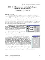
226. This
movement
is
designed
to double
the
speed by
gears
of
equal
diameters
and
numbers
of teeth
a result
once
generally
supposed
to be
impossible.
Six
bevel-gears
are
employed.
The
gear
on the
shaft, B,
is
in
gear
with two
others
one
on the
shaft,
F,
and the
other
on the
same
hollow
shaft
with
C,
which
turns
loosely
on
F. The
gear,
D,
is carried
by
the
frame,
A, which,
being
fast
on the
shaft, F,
is
made
to
rotate,
and
therefore
takes
round
D with
it.
E is
loose
on
the
shaft,
F,
and
gears
with
D.
Now,
sup-
pose
the
two
gears
on
the
hollow
shaft,
C,
were
removed
and
D
prevented
from
turning
on its
axis
;
one revolution
given
to
the
gear
on B
would cause
the
frame, A,
also to re-
ceive
one
revolution,
and
as this
frame car-
ries
with
it the
gear,
D,
gearing
with
E,
one
revolution
wouid
be
imparted
to
E
;
but
if
the
gears
on the
hollow
shaft, C,
were
re-
placed,
D
would
receive also a revolution
on
its axis
during
the one
revolution of
B,
and
thus
would
produce
two
revolutions
of
E.
227.
Represents
a
chain and chain
pulley.
The links
being
in
different
planes,
spaces
are left between them for
the teeth of
the
pulley
to
enter.
228. Another
kind
of
chain
and
pulley.
229.
Another
variety.
230.
Circular motion
into ditto. The
con-
necting-rods
are so
arranged
that
when one
pair
of
connected
links is
over
the dead
point,
or
at the
extremity
of
its
stroke,
the
other
is at
right
angles
;
continuous
motion
is thus
insured without a
fly-wheel.
231.
Drag-link
motion. Circular
motion
is transmitted from one crank to
the other.
232.
Intermittent circular motion is
im-
parted
to
the toothed wheel
by vibrating
the
arm,
B.
When
the
arm, B,
is
lifted,
the
pawl,
C,
is raised
from between the teeth of
the
wheel, and,
traveling
backward
over
the
circumference,
again
drops
between
two
teeth on
lowering
the
arm,
and
draws
with
it
the wheel.
233.
Shows
two different
kinds of
stops
for a
lantern-wheel.
6o
MECHANICAL MOVEMENTS.
2.14
235
236
237
240
238 239
241
24,2
MECHANICAL
MOVEMENTS.
61
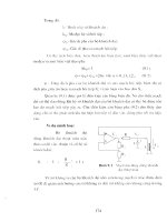
234. Represents
a
verge
escapement.
On
oscillating
the
spindle,
S,
the
crown-wheel
has
an intermittent
rotary
motion.
wheel,
and
C and B
the
pallets.
A
is
the
axis
of the
pallets.
235.
The
oscillation
of the
tappet-arm pro-
!
2
39-
An
arrangement
of
stops
for a
spur-
duces
an intermittent
rotary
motion
of
the
S
ear
-
ratchet-wheel.
The
small
spring
at
the bot-
tom
of the
tappet-arm
keeps
the
tappet
in
the
position
shown
in
the
drawing
as the ,.
240.
Represents
vaneties of
stops
for
a
arm
rises, yet
allows it
to
pass
the teeth on
the
return motion.
236.
A
nearly
continuous circular
motion
is
imparted
to
the
ratchet-wheel on
vibrating
the
lever,
a,
to
which
are attached
the two
pawls,
b
and c.
237.
A
reciprocating
circular
motion
of
the
top
arm
makes its
attached
pawl
pro-
duce
an
intermittent
circular motion of
the
crown-ratchet
or
rag-wheel.
238.
An
escapement.
D
is
the
escape-
ratchet-wheel.
241.
Intermittent circular
motion is
im-
parted
to the
wheel, A,
by
the continuous
circular
motion of the
smaller wheel with
one tooth.
242.
A
brake used
in
cranes and
hoisting
machines.
By pulling
down the end of
the
lever,
the ends of
the
brake-strap
are drawn
toward
each
other,
and the
strap
tightened
on
the
brake-wheel.
62
MECHANICAL MOVEMENTS.
2d3
244
245
1
4
247
249
250
251
\~
MECHANICAL
MOVEMENTS.
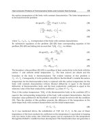
243. Represents
a mode
of
transmitting
power
from
a horizontal
shaft to two vertical
ones
by
means
of
pulleys
and a band.
244.
A
dynamometer,
or instrument
used
for
ascertaining
the amount of
useful
effect
given
out
by
any
motive-power.
It
is
used
as follows
:
A is a
smoothly-turned pulley,
secured
on a shaft
as
near
as
possible
to
the
motive-power.
Two
blocks of wood are
fit-
ted
to this
pulley,
or one
block
of
wood and
a series
of
straps
fastened
to a band
or
chain,
as
in the
drawing,
instead
of a
com-
mon
block.
The blocks
or block and
straps
are
so
arranged
that
they
may
be
made
to
bite
or
press
upon
the
pulley
by
mean.s
of
the screws
and nuts on the
top
of
the
lever,
D.
To
estimate
the amount
of
power
trans-
mitted
through
the
shaft,
it
js
only
necessary
to ascertain
the
amount
of friction of
the
drum,
A,
when it
is in
motion,
and the num-
ber
of revolutions made. At the end of
the
lever,
D,
is
hung
a
scale,
B,
in
which
weights
are
placed.
The two
stops,
C, C',
are to
maintain the lover as
nearly
as
possible
in a
horizontal
position.
Now,
suppose
the shaft
to
be
in
motion,
the
screws are to
be
tight-
ened
and
weights
added in
B,
until the lever
takes the
position
shown in
the
drawing
at
the
required
number
of
revolutions. There-
fore the
useful
effect
would
be
equal
to the
product
of the
weights
multiplied
by
the ve-
locity
at which the
point
of
suspension
of the
weights
would revolve
if
the lever were at-
tached to the
shaft.
245.
Bayonet joint.
On
turning
the
part,
A,
it is
released
from
the
L-shaped
slot
in
the
socket, B,
when it
can be
withdrawn.
246.
Represents
a
pantograph
for
copying,
enlarging,
and
reducing
plans,
etc. One
arm is
attached
to
and
turns on
the fixed
point,
C.
B is
an
ivory
tracing-point,
and
A the
pencil.
Arranged
as
shown,
if
we
trace the lines of a
plan
with the
point,
B,
the
pencil
will
reproduce
it
double the size.
By
shifting
the
.
slide
attached to the fixed
point,
C,
and the slide
carrying
the
pencil
along
their
respective arms,
the
proportion
to which
the
plan
is
traced will be
varied.
247.
A
mode
of
releasing
a
sounding-
weight.
When the
piece
projecting
from
the
bottom of the
rod strikes the bottom of
the
sea,
it is forced
upward
relatively
to the
rod,
and withdraws the
catch
from
under
the
weight,
which
drops
off"
and allows the rod to
be
lifted without it.
248.
Union
coupling.
A is a
pipe
with a
small
flange
abutting
against
the
pipe,
C,
with a screwed end
;
B
a
nut which
holds
them
together.
249.
Ball-and-socket
joint,
arranged
for
tubing.
250.
Anti-friction
bearing.
Instead
of
a
shaft
revolving
in an
ordinary
bearing
it is
sometimes
supported
on
the circumference
of
wheels.
The friction
is thus reduced
to
the least
amount.
251. Releasing-hook,
used
in
pile-driving
machines. When the
weight,
W,
is suffi-
ciently
raised,
the
upper
ends of
the
hooks,
|
A,
by
which it is
suspended,
are
pressed
in-
ward
by
the sides
of
the
slot,
B,
in the
top
of the frame
;
the
weight
is thus
suddenly-
released,
and falls with
accumulating
force
on
to the
pile-head.
MECHANICAL
MOVEMENTS.
252
CZl
255
256
, ,
257
n,
n
258
M
259
.
= 1
^
MECHANICAL MOVEMENTS.
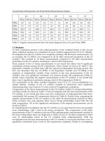
252.
A and
B are
two rollers
which
require 255.
A
flanged
pulley
to drive
or be
driven
to
be
equally
moved
to and
fro
in
the
slot,
i
by
a flat
belt.
C.
This
is
accomplished
by moving
the
piece,
D,
with
oblique
slotted
arms,
up
and
25
6.
A
plain
pulley
for a flat belt,
down.
253. Centrifugal
check-hooks,
for
prevent-
ing
accidents
in case of the
breakage
of
ma-
chinery
which
raises
and lowers
workmen,
ores,
etc.,
in mines. A
is
a frame-work fixed
to the side
of the
shaft of the
mine,
and
having
fixed
studs, D,
attached.
The drum
on which
the
rope
is wound is
provided
with
a
flange,
B,
to which the check-hooks
are
attached.
If
the
drum
acquires
a
dangerous-
ly
rapid
motion,
the hooks
fly
out
by
centri-
fugal
force,
and
one
or
other
or all of
them
catch
hold
of the
studs,
D,
and
arrest
the
drum and
stop
the descent
of
whatever
is
attached to the
rope.
The
drum
ought
be-
sides this to have a
spring
applied
to
it,
otherwise the
jerk
arising
from
the
sudden
stoppage
of
the
rope
might
produce
worse
effects
than its
rapid
motion.
254.
A
sprocket-wheel
to
drive or to
be
driven
by
a chain.
257.
A
concave-grooved
pulley
fora
round
band.
258.
A smooth-surface
V-grooved pulley
for a round band.
259.
A
V-grooved pulley
having
its
groove
notched to increase the
adhesion
of the
band.
260. A differential
movement.
The
screw,
C,
works
in
a nut secured to the hub of the
wheel, E,
the nut
being
free to turn
in
a
bearing
in
the shorter
standard,
but
prevent-
ed
by
the
bearing
from
any
lateral
motion.
The
screw-shaft
is secured
in
the
wheel,
D.
The
driving-shaft,
A,
carries
two
pinions,
F and
B. If
these
pinions
were
of such
size
as
to turn the two
wheels,
D and
E,
with
an
equal
velocity,
the screw would
re-
main at rest
;
but the
said 'wheels
being
driven at
unequal
velocities,
the screw tra-
vels
according
to the
difference of
velocity.
66 MECHANICAL
MOVEMENTS.
261
262
263
265
266
167
268
269
L
P
MECHANICAL MOVEMENTS.
261. A combination
movement,
in which
the
weight,
W,
moves
vertically
with a
reciprocating
movement
;
the down-stroke
being
shorter than
the
up-stroke.
B
is
a
revolving
disk,
carrying
a drum
which winds
round
itself
the
cord,
D. An
arm, C,
is
jointed
to the
disk
and to the
upper
arm,
A,
so that when
the
disk
revolves
the
arm, A,
moves
up
and
down,
vibrating
on
the
point,
G.
This
arm carries
with
it the
pulley,
E.
Suppose
we
detach the cord
from
the drum
and tie
it
to a fixed
point,
and then
move
the
arm,
A,
up
and
down,
the
weight,
W,
will
move
the same
distance,
and in addition
the
movement
given
to it
by
the
cord,
that
is
to
say,
the
movement
will
be doubled. Now
let
us attach the cord to the drum and re-
volve the
disk, B,
and the
weight
will
move
vertically
with the
reciprocating
motion,
in
which the down-stroke
will be shorter
than
the
up-stroke,
because the
drum is
continu-
ally
taking
up
the cord.
262
and
263.
The first of
these
figures
is
\
an
end
view,
and the second a side
view,
of
an
'
l
arrangement
of
mechanism
for
obtaining
a
I
series
of
changes
of
velocity
and
direction.
|
D is a screw
on which
is
placed
eccentrically
'
the
cone, B,
and
C
is a
friction-roller which
i
is
pressed
against
the cone
by
a
spring
or
j
weight.
Continuous
rotary
motion,
at a
uni-
form
velocity,
of
the
screw, D,
carrying
the
eccentric
cone,
gives
a series
of
changes
of
velor'ty
and
direction to the
roller,
C. It
will be
understood that
during
every
revolu-
tion
of
the cone the roller would
press
against
a different
part
of the
cone,
and that
it would describe thereon
a
spiral
of
the
same
pitch
as
the
screw,
D. The
roller,
C,
would
receive
a
reciprocating
motion,
the
movement
in
one
direction
being
shorter
than that in the other.
264.
Two
worm-wheels of
equal
diameter,
but one
having
one
tooth
more
than the
other,
both
in
gear
with the
same
worm.
Suppose
the first
wheel has
100 teeth
and
the second
101,
one
wheel
will
gain
one re-
volution
overthe other
during
the
passage
of
100
x
101
teeth
of
either
wheel across
the
plane
of
centers,
or
during
10,100
revo-
lutions of
the
worm.
265.
Variable motion.
If
the
conical drum
has a
regular
circular
motion, and the fric-
tion-roller
is made to traverse
lengthwise,
a
variable
rotary
motion of
the friction-roller
will
be obtained.
266. The
shaft has
two screws of different
pitches
cut on
it,
one
screwing
into a fixed
bearing,
and the other into a
bearing
free to
move to
and fro.
Rotary
motion of the
shaft
gives
rectilinear motion
to
the
mova-
ble
bearing,
a distance
equal
to the difference
of
pitches,
at
each
revolution.
267.
Friction
pulley.
When
the
rim
turns
in the
opposite
direction to
the
arrow,
it
gives
motion to the shaft
by
means
of the
pivoted
eccentric
arms
;
but when
it turns
in
the direction
of the
arrow,
the arms turn
on their
pivots
and the shaft is at rest.
The
arms
are held to the
rim
by springs.
268. Circular into
reciprocating
motion
by
means
of
a
crank and
oscillating
rod.
269.
Continued rectilinear movement
of
the
frame with
mutilated racks
gives
an
alternate
rotary
motion to the
spur-gear.
68 MECHANICAL
MOVEMENTS.
270 272
273
274
275
276
277