Tài liệu Mastering Revit Architecture 2008_ Part 7 docx
Bạn đang xem bản rút gọn của tài liệu. Xem và tải ngay bản đầy đủ của tài liệu tại đây (2.7 MB, 48 trang )
44831.book Page 152 Friday, October 12, 2007 12:31 AM
Please purchase PDF Split-Merge on www.verypdf.com to remove this watermark.
Chapter 6
Modeling Principles in Revit
Creating a BIM model requires modeling in 3D.This is very different from working with abstract
2D lines in order to represent your design. To work with Revit and be able to build a BIM model,
you need to have an understanding of how objects are constructed at various scales ranging from
the building mass down to furniture assemblies. You’ll need to know how various building ele-
ments interact with each other and depend on each other, what materials they are made of, and
how are they constructed and assembled. To this end, Revit provides a set of tools that enable you
to build your model and all the elements that go into the model. Understanding the principles of
modeling in the context of Revit will be essential to your success as you move deeper into building
information modeling.
In this chapter you will learn the basic modeling principles that support the design process
in Revit:
◆
The underlying concept of Sketch Based design
◆
How Work Planes, Datums, and Reference Planes are used in modeling
◆
Using Revit’s essential form making tools (Extrusion, Sweep, Revolve and Blend)
◆
Combining Solids and Voids to create complex and intriguing forms
Modeling with Revit
Designers have a long tradition of modeling before building. This activity involves the use of
pliable and tactile materials such as clay and wood to model designs fluidly. With these materials,
form can be explored with ease, and designs allowed to iterate directly in our own hands. The use
of software to model form has become a popular extension of this activity, and you only need to
look so far as the latest animated film to see how far the technology has come.
There are many software modeling tools that allow direct editing and intuitive shaping of form.
Tools such as Rhinoceros, 3ds Max, Maya, and SketchUp allow you to create free-form shapes with
relative ease. These tools are great for modeling, but they are not geared for a BIM approach to
design and documents. The elements created with these modelers are meshes, nurbs, acis solids,
and other generic geometrical shapes that are used to represent walls, slabs, roofs, and windows
but they do not have any embedded intelligence or relationships among themselves or with other
elements in the model. Further, they barely contain any metadata that can be quantified and ana-
lyzed. So, as it stands today—you will find great modelers that are not BIM and BIM applications
that are not powerful modelers. One way that Revit approaches this problem is to allow the import
and smart re-use of free-form geometries into the project and family environment.
44831.book Page 153 Friday, October 12, 2007 12:31 AM
Please purchase PDF Split-Merge on www.verypdf.com to remove this watermark.
154
CHAPTER 6
MODELING PRINCIPLES IN REVIT
The entire modeling concept in Revit is based on four base class modeling forms—extrusion,
revolution, sweep, and blend—and the combinations that these can produce.
Each of the four base modeling techniques can produce either a positive or negative shape that
can be combined to create more complex forms. Each form is derived from 2D sketches that are
drawn on Work Planes. We’ll explore in more detail what sketch based forms are in the next
section.
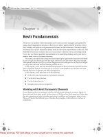
While there is clearly room for improvements when it comes to the generic modeling capabili-
ties of Revit, you will be pleasantly surprised with the variety of 3D geometry you can generate in
a short amount of time. Figure 6.1 shows an example of what’s possible.
Figure 6.1
Example of
expressive
architecture
using Revit
Sketch-Based Design
All internal modeling techniques in Revit rely on an approach called
sketch-based design,
where you
draw a shape in a special sketch mode by creating 2D lines that then generate 3D forms. When
you start modeling Revit elements, you are basically starting a sketch: Revit enters a mode in which
everything but the sketch itself is grayed out so that the focus is given to the sketch, represented in
strong magenta colored lines. Once you’ve defined the shape by creating closed loops of lines, you
click Finish Sketch, and the geometry is generated. This sketch mode is used throughout Revit.
The Floor and Roof tools both require you to first sketch 2D shapes and then generate the form
by “finishing the sketch.” Revit then applies a thickness based on the element type to the sketch.
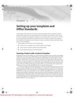
Even walls have an underlying sketch but in the case of the walls this is a sketch that can be edited
in Elevation, not plan view, as shown in Figure 6.2.
To edit the elevation of a wall, select the wall in an Elevation or 3D view and click and click the
Edit Elevation Profile button in the Options bar. Note that this only applies to linear walls.
Floors
One of the first places you’ll encounter sketch-based modeling is with the Floor and Roof tools.
When you initiate either of these tools, you are instantly placed in sketch mode. The design bar will
Image courtesy of Architect Kamal Malik
44831.book Page 154 Friday, October 12, 2007 12:31 AM
Please purchase PDF Split-Merge on www.verypdf.com to remove this watermark.
MODELING WITH REVIT
155
change (Figure 6.3), and you’ll get a set of tools specific to the task of creating 2D sketch lines and
creating lines with relationships to other model elements.
Figure 6.2
Moorish architectural
example: (A) Standard
straight rectangle
shaped wall, (B) eleva-
tion profile of that
wall changed to the
desired shape using
simple lines, (C) wall
shape result achieved
by simple editing of
the sketch in elevation ;
(D) the wall used in a
building.
Figure 6.3
The Design bar in
sketch mode
AB
CD
Image Courtesy of E. Di Giacommo
44831.book Page 155 Friday, October 12, 2007 12:31 AM
Please purchase PDF Split-Merge on www.verypdf.com to remove this watermark.
156
CHAPTER 6
MODELING PRINCIPLES IN REVIT
For example, you can either draw lines freely, or use the Pick Walls tool to generate the floor
or roof sketch lines for you by picking on walls. When using the pick walls method, you create an
explicit relationship between the sketch and the walls. The result is that when walls move, the
sketch (and thus the floor or the roof made of it) will adapt and update with the walls.
The rules for creating a valid sketch are straightforward:
◆
The line sketch has to form a closed loop of lines, and the lines have to be perfectly trimmed
at edges. You cannot have gaps or overlapping lines in the sketch. Whenever a sketch is not
complete or has overlaps, you will not be able to finish the shape and Revit will indicate that
something is wrong with an error message.
◆
When creating certain types of elements, you are allowed to sketch more than one shape
within the same sketch—this is OK as long as the two sketches do not intersect. If the one
loop of lines is within the boundaries of the other, that second loop of lines will create a hole
in the shape defined by the bigger one (Figure 6.4).
Figure 6.4
Creating a closed loop
within another closed
loop of lines results in
an opening
If you were to draw another shape within those openings, it would be positive and create another
solid piece of floor of the same type. The logic of the loops is: one is positive, the next one within it
is negative, the next one within it is positive. Remember that. (Figure 6.5)
Figure 6.5
An additional loop
of lines results in a
positive shape.
44831.book Page 156 Friday, October 12, 2007 12:31 AM
Please purchase PDF Split-Merge on www.verypdf.com to remove this watermark.
MODELING WITH REVIT
157
◆
To edit a sketch you need to be in a view that is parallel to the sketch, or a 3D view. For example,
it is not logical to edit the sketch of a wall profile in a plan view as you would not be able to
see the sketch in a way that is relevant to edit it. If you attempt to do this in plan view, Revit
will alert you and propose other views in which you CAN execute the task. The same goes
for a floor—only in plan views or 3D will you be able to edit the sketch.
◆
Sketch mode cannot be activated in Perspective (camera) view. If you select a wall or any
other element and want to edit its shape but cannot find the Edit Shape button in the Options
bar, you must be in Camera view. Switch to any other view in which the sketch makes sense
to edit.
Work Planes
Reference Planes, Reference Lines, Datum Planes, Work Planes…what are they? In order to master
modeling techniques in Revit, you will need to understand the concept of Work Planes.
The Work Plane is nothing more than a 2D plane that is used to sketch on. For example, when
you are in a plan view and start sketching a floor, the Work Plane is set to the level associated with
the plan view you are working in. The majority of views in Revit (plans, 3D views, or views set in the
Family templates) have predefined Work Planes set automatically when they are created. Views
such as Sections and Elevations require you to manually pick a Work Plane in order to add 3D ele-
ments to those views.
A Work Plane can be understood as a surface on which you draw something. To understand this
better, imagine you are holding a marker in your hand and have a space in front of you—can you
draw with the marker in the space? No. you need a piece of paper, glass, wall, some kind of a sur-
face to draw on. So, a Work Plane defines a surface on which you can draw something as a base to
build geometry. You can define a Work Plane by drawing a Reference Plane, picking a face from an
existing element, or use an existing Level (datum) as a reference. Let’s look a bit more closely at the
types of Work Planes available in Revit:
Reference Planes
These are 2D planes that exist in 3D space. They are not visible in 3D views, but can be seen ”edge on“
in other views (plan, section, elevation) and are represented as green dashed lines. These lines are
not view-specific and will appear in other perpendicular views such as plans, sections and eleva-
tions. Even though Reference Planes look and feel like ordinary lines, they do not have a ”real“
beginning nor an end. They are symbolic representations of infinite planes. This means you cannot
reference to the beginning or end of a Reference Plane in order to make something like an angular
constraint or dimension.
Reference Planes are the essence of content creation in the Family Editor as they are used to cre-
ate the parametric skeleton to which geometry is then attached. They can also affect how other ele-
ments relate to the family by giving the Reference Planes various states. A Reference Plane can be
set as Not A Reference, Weak, or Strong; and it can be defined as a reference for the Left, Right,
Front, Bottom, Back, or Center position. The selection of these options is important in the Family
Editor environment as they define references for snapping. Just to give you an idea, when you have
two crossing references that are set as Strong, they will define the insertion point of an element
when placing it in the Project environment (as shown in Figure 6.6). In Figure 6.6, the two centrally
positioned Strong references define the insertion point of the element. The Weak references serve
only as secondary snaps.
In a project, Reference Planes can be used to drive geometry (see Figure 6.7).
44831.book Page 157 Friday, October 12, 2007 12:31 AM
Please purchase PDF Split-Merge on www.verypdf.com to remove this watermark.
158
CHAPTER 6
MODELING PRINCIPLES IN REVIT
Figure 6.6
A working desk
Figure 6.7
Reference Planes are
used extensively in
the family editor to
create parametric
constraints that can
drive forms and define
snapping references
44831.book Page 158 Friday, October 12, 2007 12:31 AM
Please purchase PDF Split-Merge on www.verypdf.com to remove this watermark.
MODELING WITH REVIT
159
Reference Lines
These were designed to overcome the limitation of the Reference Planes and their inability to define
constraints that reference a point, direction, and angle. Unlike with reference Planes, the start and
end points of a Reference Line can be referenced and used for dimensioning. A popular use of a
Reference Line is to define door swing openings by creating an angular relationship between the
door leaf position and the closed state of the door leaf. Other differences between Reference Lines
and Reference Planes are that you cannot name the Reference Lines and you can only select them
graphically.
Reference Lines define two workplanes—one is the plane on which the Reference Line was drawn,
and the other is perpendicular to it (see Figure 6.8).
Figure 6.8
Reference Lines are
used to control door
swings and opening
angle in families.
Levels
These are horizontal Datum planes that define the levels in a building and can also be used to
denote important horizontal references in a building (attic height, etc.). Levels are only created and
visible in Section or Elevation views. Each level commonly has a corresponding floor plan view
associated with it, although it is possible to make levels with no associated floor plan. For example,
a level may define the Top Of Steel in a building section, but there is no need to have a floor plan
view of that level. For that case, you can create levels without plans by unchecking the option Make
Plan View in the Options bar when the level tool is activated. This will create a level that appears
black and white, rather than blue—indicating that there is no hyperlinked view. Note that when
you create new levels using the Copy tool, the newly created level an elevation view, the newly cre-
ated levels will appear as this black-and white version, as copying levels will not auto-generate new
floor plans. If you need to convert a level that has no view associated with it to a level with a view
associated, use the Floor Plan… tool in the View design tab in the Design bar. You will then be able
to choose to add a view to any existing Level in the project.
44831.book Page 159 Friday, October 12, 2007 12:31 AM
Please purchase PDF Split-Merge on www.verypdf.com to remove this watermark.
160
CHAPTER 6
MODELING PRINCIPLES IN REVIT
When placing elements, they are automatically associated with the Level they are drawn on so
that when the level changes position, so will the elements on that level. All sketch based families
such as floors, roofs, ceilings, and stairs will be associated with at least one level. Levels can define
both the bottom and top constraints for several elements in Revit, including walls, stairs, and ramps.
Grids
These are vertical planes used as standard references in the construction industry for creating loca-
tion grids on the site as well as a communication reference between the building participants. These
construction data are used to accurately define locations for elements such as columns and beams
or position of main structural walls or exterior shell. You can associate elements with the Grids so
that when the grid system changes, it controls the position of the associated elements. A good example
for that would be columns associated with grid intersections. As with a level, when a grid is moved,
associated elements move with the grid. The creation, graphic representation, and control editing
of grids is similar to that of levels (see Figure 6.9).
Figure 6.9
Grids are datum
planes that can be
used to control other
elements such as
beams and columns.
Once all the Datum planes in Revit have been defined, they will appear in all views that they
intersect.
So, if you work on a project in a system of grids, you need only draw the grid system once in
a floor plan view, and the grids will be visible in every other plan or ceiling view. This may not
always be a desired behavior, for example, if your project has a base of 5 floors of shopping with a
30-story hotel above, (like the model shown in Figure 6.8) it’s likely you’ll have separate structural
bays for each part of the building. You don’t need to see all grid lines of the shopping base in the
tower, and vice versa. To deal with these scenarios, you can use a
Scope Box
. This will allow you to
control in which views a grid will appear.
Important note: Grid lines will show in Section or Elevation view ONLY if the view is cut per-
pendicular to the Grid line. In no other case will the grid line appear. This is done to avoid confusion
on construction site due to misleading graphic description.
Extending Datum Planes
If you wish to expand grids or levels to encompass a larger portion of your model, you can use the Con-
text Menu of the grids and select Maximize Extents. This will extend the datum planes you have
selected to the maximum extents of the model geometry.
44831.book Page 160 Friday, October 12, 2007 12:31 AM
Please purchase PDF Split-Merge on www.verypdf.com to remove this watermark.
MODELING WITH REVIT
161
Scope Boxes
These are used when you have multiple floor plans where the gridlines aren’t the same for all levels.
This tool limits the range in which data elements (grid lines, levels, and reference lines) appear. In
our example of a building with a base and tower, two separate scope boxes are created for each
major volume of the building. The grids in each part of the building are then assigned to appropri-
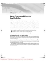
ate scope boxes. Figure 6.10 shows how scope boxes work in a 3D view.
Scope boxes are visible in 3D views (although not in camera views), and you can easily manip-
ulate their extent directly using the grip controls. Assigning gridlines or other datums to a scope
box is easy: Select the gridlines, Select the gridlines and in the Element Properties choose Scope Box
and select the scope box where the datums should belong. Figure 6.10b shows the Element Proper-
ties dialog box for the gridlines and the associated scope box.
Figure 6.10
(A) This building
consists of two main
volumes, low volume
with shopping function
and a tower with hotel
use. These two vol-
umes use separate
grid systems and thus
two different Scope
Boxes are created to
control the visibility
of the separate Grids.
(B) Grid element prop-
erties indicate the
Scope box to which
the grid belongs.
Work Planes in a Nutshell
Before moving on to look at using work planes in practice, let’s take a moment to summarize the
basic theory.
A Work Plane is the
active plane
you are working on in any given graphic view. It is used when
you are creating objects by sketching or placing. Think of it like the “UCS” (user coordinate system)
in AutoCAD that allows you to work in specific orientations and directions. Every view has an
A
B
44831.book Page 161 Friday, October 12, 2007 12:31 AM
Please purchase PDF Split-Merge on www.verypdf.com to remove this watermark.
162
CHAPTER 6
MODELING PRINCIPLES IN REVIT
active Work Plane. Figure 6.11 graphically explains the Work Plane. There are a few simple rules
when using or understanding a Work Plane:
Figure 6.11
Concept diagram be-
hind Work Planes
◆
The Work Plane is set by selecting a Reference Plane/Reference Line; a Datum Plane (like a
Level, Grid) or a planar face of a Model element. Often it is pre-set and you do not need to
explicitly set it.
◆
Many elements in Revit use the active Work Plane to know where to sketch or place objects
(some objects are limited to only horizontal or vertical Work Planes).
◆
The Work Plane is also used when you are modifying objects. When you drag or move an
object it is typically constrained to be along that plane.
◆
When you set the Work Plane to be based on other selectable elements it creates a “depen-
dency” or relationship to the underlying reference you selected. If the underlying object is
moved, the Work Plane is moved to stay aligned to it. Any objects created on the Work Plane
will also update.
Working with Work Planes
When creating elements that are not standard (orientation or geometry) or not automatically con-
nected to a Work Plane, to create them you will need to will need to select the Work Plane tool from
the Toolbar. This displays the Work Plane dialog shown in Figure 6.12; it’s a good idea to under-
stand its options.
Name
This option displays either the available Levels and Grids in the project or the Reference
Planes that you have created—if you have named them. This is why naming a Reference Plane
is a very important thing.
Lines Sketched on
Active Work Plane
Model Face
Reference Plane
(or other Datum Plane)
Active Work Plane
(based on Model Face
or Datum Plane)
44831.book Page 162 Friday, October 12, 2007 12:31 AM
Please purchase PDF Split-Merge on www.verypdf.com to remove this watermark.
MODELING WITH REVIT
163
Pick a plane
This option allows you to select a plane interactively in the model. The selection is
graphical/visual and you need to click on a Reference Plane, wall face, faces of other elements—
native or linked in the project, any level or grid that you want to become the active Work Plane
for the task at hand. Figure 6.13 shows the effect of selecting different planes on which to sketch
and create a void extrusion.
Figure 6.12
The “Work Plane”
dialog is where you
can set the active
Work Plane for a view.
Figure 6.13
The same mass and
the same 2D shape
extruded as a hole:
(A) the extrusion
shape is drawn on the
front face of the mass,
(B) the extrusion is
drawn on the back
face of the mass.
Pick a line and use the Work Plane it was sketched in
With this option Revit converts the
Work Plane on which the line was created into the active Work Plane. When you select a Work
Plane that is perpendicular to your current view, Revit will open a new
Go to View
dialog that
will give you options to select a view in which the chosen Work Plane can be worked on.
(Figure 6.14)
Figure 6.14
The “Go To View”
dialog will list views
where you can work on
the active Work Plane.
AB
44831.book Page 163 Friday, October 12, 2007 12:31 AM
Please purchase PDF Split-Merge on www.verypdf.com to remove this watermark.
164
CHAPTER 6
MODELING PRINCIPLES IN REVIT
Work Plane Visibility
You have the option of displaying the Work Plane visually in your view. When visible in 3D, the
Work Plane is shown as a semi-transparent grid face (Figure 6.15). By activating the Work Plane
Visibility, you’ll see where you will be adding new elements. You can see the Work Plane change
location by using the Pick Plane option in the Work Plane dialog. Select on model faces and you’ll
see the active Work Plane change.
Figure 6.15
Making the Work
Plane visible helps
you understand the
active Work Plane in
a 3D view.
If you are not sure where your active Work Plane is, click the Work Plane Visibility tool in the
tool bar:
Other Work Plane Operations
Revit will let you rotate a Work Plane, by clicking on its grid and selecting Rotate from the toolbar.
This in turn affects how new elements will be placed on that Work Plane. You can also use the Work
Plane grid to align elements to, and lines will snap to the grid. (Figure 6.16)
Figure 6.16
When the Work Plane
grid is rotated, new
elements placed on
the Work Plane will
also be “rotated”.
44831.book Page 164 Friday, October 12, 2007 12:31 AM
Please purchase PDF Split-Merge on www.verypdf.com to remove this watermark.
MODELING WITH REVIT
165
To Change the Work Plane associated with an element, select the element, and then select the
Edit Work Plane
button in the options bar and select another Work Plane using one of the methods
in the dialog.
To disassociate an element from a Work Plane, select the element, then select
Edit Work Plane
button from the options bar to display the window shown in Figure 6.17 and then select the Disso-
ciate button. The element will then be free to move anywhere in the model. Note that this option
will only be available for Work Plane based families.
Figure 6.17
The Work Plane dialog
allows you to set Work
Plane of element, or
disassociate it from its
Work Plane.
Once you have dissociated an element from its Work Plane, you will notice that the value for the
Work Plane instance parameter will be set to <not associated>. Most importantly, you will notice
that the element will be free from constraints and is free to be moved in any three dimensional
direction.
To Rehost elements from one host (wall, floor, or roof for example) to another, you can use the
Rehost button in the Options Bar when an element is selected. This allows you to select a new host
to place the element. With this tool, you can choose any new host—it does not have to be in same
plane as the original. For example, you can select a window in one wall, click the Rehost button,
then choose a new wall for the window.
Figure 6.18 shows an extruded shape originally created on a horizontal Work Plane. Using the
Rehost tool, the form can be placed on any surface in the model.
Figure 6.18
(A) original condition,
(B) desired reposition-
ing of the curved ele-
ment, (C) the element
is rehosted and a rela-
tionship between the
two elements has
been created, (D) the
host changed its
geometry and the
hosted elements
follows the change.
AB
CD
44831.book Page 165 Friday, October 12, 2007 12:31 AM
Please purchase PDF Split-Merge on www.verypdf.com to remove this watermark.
166
CHAPTER 6
MODELING PRINCIPLES IN REVIT
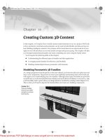
Using Work Planes with Revit Elements
Below you’ll see two versions of the same building, with roofs that use the same sketch profile but are
drawn on two different Work Planes. Image A shows a roof by extrusion sketched on a Work Plane par-
allel to the exterior wall; B shows the same roof sketched on a Work Plane rotated 45 degrees with
respect to the exterior wall. Notice the difference!
Creating a Roof by Extrusion (Default Work Plane)
Take the following steps to see for yourself how version A was created:
1.
Draw four walls in plan view in the shape of a square.
2.
From the Basic design bar, select the Reference Plane tool and draw a Reference Plane parallel to the
south wall:
3.
Pick the Reference Plane and go to element properties. Give it a Name, “Front Roof Plane”.
4.
From the Modeling design tab, Select the Roof tool and select Roof By Extrusion.
A
B
44831.book Page 166 Friday, October 12, 2007 12:31 AM
Please purchase PDF Split-Merge on www.verypdf.com to remove this watermark.
MODELING WITH REVIT
167
5.
You will be prompted to select a Work Plane:
From the Name list, select the named Reference Plane you just drew. You’ll be asked to open a view to
begin sketching. Choose the South Elevation.
6.
Sketch a roof in arc shape as shown here and finish the sketch.
7.
Go to the default 3D view and using the blue arrows, adjust the length of the roof to make sure it
extends beyond the exterior walls as shown here.
44831.book Page 167 Friday, October 12, 2007 12:31 AM
Please purchase PDF Split-Merge on www.verypdf.com to remove this watermark.
168
CHAPTER 6
MODELING PRINCIPLES IN REVIT
8.
While still in the 3D view, select all the walls. Click the
Attach
button in the Options bar and then
select the roof to attach the walls to the roof. The resulting roof should look something like this:
9.
To make the roof end at the edge of the exterior walls, select the roof in plan view and select the
option
Cut Plan Profile
in the Option bar. This allows you to cut off the extruded roof exactly at the
edge of the building, regardless of its shape. In this example, draw two rectangles that cut the roof
up to the face of the walls.
Wall
Roof
Cut Plan Profile
Cut Plan Profile
44831.book Page 168 Friday, October 12, 2007 12:31 AM
Please purchase PDF Split-Merge on www.verypdf.com to remove this watermark.
MODELING WITH REVIT
169
After using Cut Plan Profile, the final result for the first roof looks like this:
Creating a Roof using a 45 degree oriented Work Plane as a reference
To obtain the second roof (B), repeat all previous steps, but draw the Reference Plane at a 45 degree angle
to the building as show below. Remember to give the Reference Plane a different name in the Element
Properties dialog.
44831.book Page 169 Friday, October 12, 2007 12:31 AM
Please purchase PDF Split-Merge on www.verypdf.com to remove this watermark.
170
CHAPTER 6
MODELING PRINCIPLES IN REVIT
Principles of Modeling in Revit
Revit is much more than a 3D modeler. It is built specifically for architects and has behavioral rules
built into many of the architectural elements that make up the building. For example, walls usually
are vertically extruded rectangular shapes; floors and ceilings are horizontal extruded shapes with
constant thickness. These major building elements (System Families) use a restricted sketch-based
approach because those restrictions make sense for these types of elements. This is one of Revit’s
major differences compared with a generic modeler where you can model anything, any way you
like. In Revit, the type of element you are modeling will present a more tailored set of creation tools.
You draw a wall by defining its start and end point, which will determine its position and
length. The width of the wall and its height are determined by the wall properties. The wall
becomes 3D immediately with each click of the mouse. Roofs and Floors, on the other hand, require
a definition of a sketch that determines their outer shape while their thickness is what is defined in
the Element properties of the Roof or the Floor.
Once the envelope of the building has been established with walls, floors, and roofs (the system
families) you progressively add windows, doors, furniture, plumbing fixtures, and so on (standard fam-
ilies) to the model. These elements rarely depend on the context of the building and are usually built
off site and manufactured in some factory in real life. In Revit, a good selection of these elements
is pre-prepared and saved in a library for use across multiple projects. These loadable elements are
all created in the Family Editor using a combination of simple geometric forms that can be associ-
ated with parametrically driven dimensions. For example, a chair can be created with a combina-
tion of sweeps, blends, extrusions, and revolves. The same applies to a lighting fixture, a sitting
bench, a plumbing fixture—you name it. Figure 6.19 shows samples of standard “loadable” family
types.
The finished roof looks like this:
44831.book Page 170 Friday, October 12, 2007 12:31 AM
Please purchase PDF Split-Merge on www.verypdf.com to remove this watermark.