Báo cáo nghiên cứu khoa học: " STUDY ON DEVELOPMENT OF AN AUTOMATIC MARKING ROBOT" pdf
Bạn đang xem bản rút gọn của tài liệu. Xem và tải ngay bản đầy đủ của tài liệu tại đây (673.44 KB, 9 trang )
TẠP CHÍ PHÁT TRIỂN KH&CN, TẬP 11, SỐ 03 - 2008
Trang 97
STUDY ON DEVELOPMENT OF AN AUTOMATIC MARKING ROBOT
Le Hong Loan, Pham Dang Khoa, TranThien Phuc, Nguyen Tan Tien
University of Technology, VNU-HCM
(Manuscript Received on November 01
st
, 2007, Manuscript Revised March 03
rd
, 2008)
ABSTRACT: This paper studies on development of an automatic marking robot. To
welding the “Draft Mark” for a ship, an automatic welding system, called automatic marking
robot, is developed. Software and hardware of the system are designed for this purpose.
Experiment has been done to verify the proposed solution.
1. INTRODUCTION
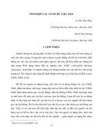
Outside of the ship there are some kinds of mark used to describe some properties of the
ship, such as: name of ship, port of registry, draft mark, …as shown in Fig.1. In ship building
manufacturers, this work has been done by skill welders. However, manual work welding is
poor work surroundings and time-consuming. To overcome these disadvantages, some
researchers focus to design an auto welding robot which can carry out the task with high speed
and accuracy degree. S.W. Ryu et al.
[1]
in Samsung Heavy Industry had developed SR-MARK
robots to weld draft mark automatically. There are two kinds of SR-MARK robot: SR-MARK
I uses for welding draft mark on the flat surface and SR-MARK II uses for welding draft mark
on the curved surface. Both of them have been experimented successfully in laboratory.
Fig1. Marks outside of the hull
[1]
In Vietnam, the shipbuilding industry trades and production achievements have increased
with the annual growth rate reaching 30 percent. The development target to 2010 is regarding
and improving the shipyards in order to have technology equal to the ASEAN shipbuilding
industry, while the localization rate of domestically made products will rise to 60-70 percent of
the products. (
Source: VINASHIN). Therefore, searching and achieving new technology for
applying in to shipbuilding industry is very important.
This study includes two steps: the first step aims to solve the problem of automatic
welding draft mark in the flat surface; and the second step is to extend the results for general
ship hull surface. This paper deals with the first one: CAD interface and robot structure design
including hardware and software. The project is going on in Machine Design Laboratory.
Experiment had been done and some conclusion remarks base on the results are given.
Science & Technology Development, Vol 11, No.03- 2008
Trang 98
2. LOAD LINE STANDARD IN BRIEF[6]
The purpose of a load line is to ensure that a ship has sufficient freeboard and thus
sufficient reserve buoyancy. The freeboard on commercial vessels is measured between the
uppermost continuous deck and the waterline and this must not be less than the freeboard
marked on the Load Line Certificate issued to that ship.
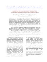
This symbol, also called an international load line or Plimsoll line, indicates the maximum safe
draft, and therefore the minimum freeboard for the vessel in various operating conditions. The
original "Plimsoll Mark" was a circle with a horizontal line through it to show the maximum draft
that a ship may load to. Additional marks have been added over the years to allow for different
densities of water and expected sea conditions.
Letters may also appear to the sides of the mark indicating the classification society that
has surveyed the vessel's load line. The initials used include AB for the American Bureau of
Shipping, LR for Lloyd's Register, and NV for Det Norske Veritas. These letters should be
approximately 115 millimeters in height, 75 millimeters in width and 25 millimeters in
thickness.
Fig 2. Load line mark and line for commercial sailing vessel
The letters on the Load line marks have the following meanings:
•
TF - Tropical Fresh Water
•
F - Fresh Water
•
T - Tropical Seawater
•
S - Summer Seawater
•
W - Winter Seawater
•
WNA - Winter North Atlantic
3. MAJOR PROBLEMS
There are two important points which need to be solved. The first one is to track the
designed welding line. In this problem we control the movement of welding torch to create a
contour which alike as the profile designed by users. The second one is to control of welding
speed according to the shape of welding line. To solve this problem is to maintain the width of
welding path as constant as possible.
TẠP CHÍ PHÁT TRIỂN KH&CN, TẬP 11, SỐ 03 - 2008
Trang 99
4. PROPOSED SOLUTIONS
4.1 Hardware design overview
The hardware is design to test the accuracy of the data transmission program and robot
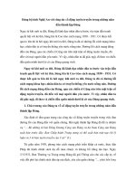
tracking control system. The designed robot can move welding torch follows the specified
profiles (include lines and circular line) by controlling
YX
−
coordinates. With these purpose,
the experimental equipment includes two sliding arm for two perpendicular directions which is
something similar to 2D table as shown in the Fig.3. One slide uses for
X
direction and the
other uses for
Y direction. They are driven using 2 step motors. The accuracy degree of the
designed model depends on pitch of screws and the revolution of these step motors. This
model can perform in size of
m8.0 length and m6.0 width. The welding speed is up
to
minm /1.
The control system includes a PC-base processor used to generate the Cartesian coordinate
due to interpolation algorithm; and a microcontroller used to transmit the data from PC and
control the welding motion.
Fig3. Experiment setting-up
4.2 Data transformation
Currently, many companies use CAD program to design their products. In this study,
information from CAD files is used to generate robot welding programs and well-known
AutoCAD software is chosen to draws letters which will be welded. General welding line
compounds from straight and circular line. Therefore tests with letters and numbers are used.
One letter was just in area of
2
7070 mm×
as shown in Fig.4.
Science & Technology Development, Vol 11, No.03- 2008
Trang 100
Fig 4. Letter A (only lines) and letter B (lines and arcs) in dwg format
The flow of data is processed as shown in Fig.5.
Fig5. The flow of data
AutoCAD software can generate different types of format including the dxf one, an ASCII
file. It includes all the information about the drawing such as: start point and end point of line,
center point and radius of circular, … This information can be extracted and saved as text
format by a simple application called Dxf2Txt. Therefore a text file can be read and processed
easily. It is used to stored position information.
Fig 6. The original file and the coordinate file generated by Dxf2Text application
4.3 Interpolation algorithm[6]
As we known, data in txt files just use to define lines or arcs in the drawing and can not be
used to control the hardware. To solve this problem, an interpolation program was written. It
can read data in files and give all points coordinates in lines or arcs with a pre-identified
revolution. This program based on the well-known Bresenham interpolation algorithm.
Interpolating a segment of the straight line
Consider the simplest line which passes the origin of coordinate and ),( ba point
(
0ab>>). This method is called the midpoint interpolation algorithm (Fig.8.a). The
equation of the straight line is 0
=
−
aybx with k is the increment of ),( yx coordinates after
each interpolation step. It is also known as the revolution of interpolation. The smaller
k is,
TẠP CHÍ PHÁT TRIỂN KH&CN, TẬP 11, SỐ 03 - 2008
Trang 101
the more points are interpolated and the more accuracy the lines are. The flow chart of straight
line interpolation is shown in Fig.7.
Fig7. The flow chart of straight line interpolation
By exchanging
x
and
y
coordinate or starting point and ending point, we can transform
all lines into the mentioned above form. Therefore, any lines in the coordinate plane can be
interpolated using this method.
(a) (b)
Fig 8. Interpolation algorithm for (a) a straight line, and (b) a circular line
Interpolating a circular line
Consider the circular line in the first 1/8 coordinate plane and its center point is the origin
(Fig.8.b).
Science & Technology Development, Vol 11, No.03- 2008
Trang 102
Fig 9. The flow chart of circular arc interpolation
The circle equation is
0
222
=−+ ryx
. Following the same steps, we can calculate
formulas to interpolate for all circular line in the coordinate plane. The flow chart of circular
line interpolation is shown in Fig.8.
Users interfaced application
Based on the above algorithm, the interpo-lation program was written. This application
can get the letters which the user wants to weld. Then it reads the appropriate text file and
defines the elements of the letter such as the starting point and the ending point of line. After
that, program interpolates the letter into an array of points. These points are Cartesian
coordinates of
X
and
Y
axes. From this array, the application redraws the letters will be
welded. This function helps users check whether it is working properly.
Fig 10. (a) The interpolation program and (b) Result of the interpolation: array of coordinates
4.4 Data transmission
The interpolation processing interpolates character into an array of points. The array is
stored in specific location in PC. Then the robot controller will be connected to PC to
download the appropriate data array. This data transmis-sion program includes the simulation
application based on Visual Basic 6.0 and a data line through RS232 serial port. Due to many
advantages, I2C protocol is used to connect the microcontroller with external components.
This protocol is as simple and high speed as required.
TẠP CHÍ PHÁT TRIỂN KH&CN, TẬP 11, SỐ 03 - 2008
Trang 103
4.5 Motion control
Continuously tracking the designed welding path is very important. The difference
between the welding path and the designed path depends on the resolution of Cartesian
coordinates of the hardware.
The more accuracy, the better welding path is. After downloaded from PC, coordinate
array is stored in random access memory (RAM) of microcontroller. After welding a character,
this memory is cleared to wait for the next one.
The size of Cartesian coordinate array depends on interpolative revolution. With high-
revolution, this array will exceed the capacity of internal RAM of the microcontroller. In order
to balance between the desired preciseness and the storable ability of microcontroller,
mm05.0
interpolative resolution is used. So each element of array is an 8-bit signed integer number. By
processing this array, the motion control program can define the distance and the direction of
the movement. Then it regulates the driven motors following these parameters.
In case of lack RAM due to big size of transmission data, external memory is used. With
lager RAM capacity, bigger size letter with higher resolution can be performed.
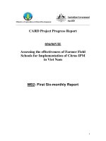
5. EXPERIMENTS AND DISCUSSION
To verify the effectiveness of proposed modeling and controller, experiments have been
done. As mentioned above, the resolution of
mm5.0
with
2
7070 mm×
is used for each
character. All the parameters of welding process are setup and simulated before running. The
current and voltage of welding machine are adjusted depending on the thickness of steel.
Experiment had been done with
mm5
thickness flat steel. The welding velocity is set
with
smm/10
.
Fig 11. Result of the first welding test
Fig.11 shows the result of welding test. These shapes are same as the character designed.
The width of welding path is
mm8 . It satisfies the request of welding. The height of character
is
mm78 .
With intersected-contoured character, the work piece will be overheated and melted. This
problem can be solved if the character is designed bigger. Thus, the work piece can avoid
being heated at a same position for a long time.
Alternative solution
As discussing above, heat effect causes the welding path to melt. So, the width of welding
path is not maintained constant. It isn’t as good as required. With small size letters, this effect
shows evidently as Fig.12.
Science & Technology Development, Vol 11, No.03- 2008
Trang 104
Fig 12. Heat effect on welding path
To reduce heat effect, the letters size must be larger. As a result, the Cartesian coordinate
array exceeds the capacity of RAM. An external EFPROM is used to enlarge the system
memory. These letters are designed in
2
200200 mm×
area. This experiment is done with 6mm
thickness flat steel and the velocity is
smm/8
.
Fig 13. Result of the last welding test
These parameters are defined in proper condition and may be changed in other cases.
Further discussions
Although heat effect is reduced in the last experiment, the width of welding path is not a
constant. To completely solve this problem, we need an auto adaptive system which can adjust
welding velocity to compensate the effect of heat.
Moreover, all experiments in this paper are done with flat steel while the surface of ship is
curve. We need curve sensor to maintain constant distant along
Z
axis. This research will be
accomplished in someday.
TẠP CHÍ PHÁT TRIỂN KH&CN, TẬP 11, SỐ 03 - 2008
Trang 105
6. CONCLUSION
This paper studies on development of mark welding robot. The robot includes mechanical
and control systems determined by many experiments. The control system, which is based on
interpolate algorithm to generate Cartesian coordinate array, used to regulate the movement of
two directions. The experiments results show that the robot can be used for welding every
character having DXF data with high-qualified. In future, it can be developed into upper stage
with three-directions welding.
NGHIÊN CỨU ROBOT HÀN MỨC CHỈ THỊ
Lê Hồng Loan, Phạm Đăng Khoa, Trần Thiên Phúc, Nguyễn Tấn Tiến
Trường Đại học Bách khoa, ĐHQG-HCM
TÓM TẮT: Bài báo trình bày các nghiên cứu bước đầu về khả năng thiết kế chế tạo một
robot hàn mức chỉ thị ứng dụng trong việc hàn “Draft Mark” cho tàu thủy. Phần cứng và
phần mềm cho hệ thống đã được thiết kế nhằm thử nghiệm khả năng này. Các thí nghiệm đã
được triển khai trong phòng thí nghiệm để chứng minh mức độ khả thi của phương án đề nghị.
REFERENCES
[1]. S.W. Ryu, H.G. Kim, J.C. Lee and S.H. Kim, Development of Automatic Mark
Welding Robot
, Proceeding of International Conf. on Computer Application in
Shipbuilding (ICCAS2005), pp. 415-421, Korea, June (2005).
[2].
J. Norberto Piers, T. Godinho and P. Ferreira, CAD Interface for Automatic Robot
Welding Programming
, Industrial Robot: An Indus-trial Journal, Vol. 31, No. 1, pp.
71-76, (2004).
[3].
D.I. Kim, Study on Interpolation Algorithms of CNC Machine Tools, Proceeding of
Industry Applications Conference, Vol. 3, pp. 1930-1937, USA, Oct. (1995).
[4].
D.I. Kim, J.I. Song and S.K. Kim, Dependence of Machining Accuracy on
Acceleration / Deceleration and Interpolation Methods in CNC Machine Tools
,
Proceeding of Industry Applications Society Annual Meeting, Vol. 3, pp. 1898-1905,
USA, Oct. (1994).
[5].
J. E. Bresenham, Algorithm for computer control of a digital plotter, IBM Systems
Journal, Vol.4, No.1, pp. 25-30, (1965).
[6].