Báo cáo nghiên cứu khoa học: " DYNAMIC MODEL AND CONTROL FOR BIPED ROBOT" pps
Bạn đang xem bản rút gọn của tài liệu. Xem và tải ngay bản đầy đủ của tài liệu tại đây (328.33 KB, 8 trang )
TẠP CHÍ PHÁT TRIỂN KH&CN, TẬP 11, SỐ 03 - 2008
Trang 41
DYNAMIC MODEL AND CONTROL FOR BIPED ROBOT
Nguyen Quoc Chi
(1)
, Duong Mien Ka
(1)
, Chung Tan Lam
(1)
, Le Hoai Quoc
(2)
(1)University of Technolog, VNU-HCM
(2)
Department of Sciences and Technology of HCMc
(Manuscript Received on November 01
st
, 2007, Manuscript Revised March 87
th
, 2008)
ABSTRACT: In this paper, a control method for a nonlinear model of a 7 DOF biped
robot is discussed. The Walking gait is generated by controlling the position of the trunk of the
robot to track a desired trajectory which based on analyzing the dynamics of a three
dimensional inverted pendulum. The motion of a three dimensional inverted pendulum is
constrained to move along a defined plane. One challenge in motion control of biped walking
is high nonlinearities of the dynamics and inaccuracy of the parameters in the biped model.
1. INTRODUCTION
One challenge in motion control of bipedal walking is the high nonlinearities of dynamics
and the inaccuracy of the parameters in biped models. The goal of the control law in this paper
is to accommodate signal control so that the positions of each joint must track down the
trajectory designed in the previous Motion planning section. This control law computes
necessary torques to accommodate dynamics model so that the actual angles at each joints
track the angles of the designed trajectory with a minimum error. The problem can be
described as follow:
After obtaining angles θ from the dynamics model of the biped robot in absolute co-
ordinate system:
(
)
()
τθθθθθ
=++ GVM
&&&
,)( (1)
We convert them into movements in generalized co-ordinates at each joint; q is relative
angle between links.
() ()
τ
=++ qGqqVqqM
&&&
,)( (2)
At this moment, we have a state vector
⎥
⎦
⎤
⎢
⎣
⎡
q
q
&
which expresses the state of an object. We
also express referential vector of input signal
⎥
⎦
⎤
⎢
⎣
⎡
r
r
&
, this vector was defined from the motion
planning section. We build the closed- loop control system of the object to generate the vector
of tracking error
)(te
between the input signal and feed-back signal. The goal of the control
law is to provide a signal
τ
so that the signal of tracking error is going on for Zero,
0)( →te
Another challenge is the control of biped during Double Phase. About the general
overview, we see that motion of a biped robot with Double phase has the advantage that it is
more convenient to realize the stable motion and can fulfil more tasks than that only walking
with Single phase. However it becomes more difficult when controlling a biped Double phase
than that of the Single phase. Motion of a biped robot during Double phase can be described as
the motion of dynamic system under holonomic constraints. However, in the case of using
natural coordinate system, if we do not well in tracking down designed motion trajectory
Science & Technology Development, Vol 11, No.03- 2008
Trang 42
during the control, the constraints are difficult to be satisfied. Generally, approaches require to
have an accurate estimation of dynamics model or to simplify the model. In simplification of
the model, we can ignore some aspects, regardless of dynamics loading capacity. The
interaction of parts and pre - unknown noise signals. As we know, it is difficult to obtain an
accurate estimation of physical parameter of complicated models with the interaction of parts
of a robot and under the force of gravity. Besides, the effect of noise loading capacity by
friction on the system cannot be ignored. In this paper, the writer uses a robust damping
control technique so-called RDC which was mentioned in reference book [2]. A RDC control
model was built to apply to a biped robot so that it is not necessary to have estimated
parameters. This control provides error compensative control signal based on the pre- designed
motion trajectory and the data of measurement of velocity and the position of each joint. In
addition, the parameters of this control model are built so that they can be adjusted easily.
2. BUILDING RDC CONTROL MODEL
2.1 Dynamic Equations and Hypotheses
We see that, in both of single phase and double phase, dynamics equations can be
described as the following equation:
Rdr
FqCqM
ττ
=+++
••••
(3)
In equation [3], F is a vector which describes the effect of gravity and friction force,
d
τ
is
respective torque which describes the effect of noise on Biped robot. In order to be convenient
for solving the problem, we give 2 hypotheses as follow:
Hypothesis 1: (noise signal effects on covered Biped): Noise signal changes respect with
time
d
τ
in the dynamics equation of covered manipulator. It is described by a mathematical
expression that is
Nd
ττ
≤sup
; here
N
τ
is a positive constant.
Hypothesis 2: (effecting of gravity and friction force is also covered):
The vector
⎟
⎠
⎞
⎜
⎝
⎛
•
qqF ,
is covered by
••
+≤
⎟
⎠
⎞
⎜
⎝
⎛
qqqF
322
,
ξξ
, here,
2
ξ
and
3
ξ
are positive
constants.
With these hypothesises we can build RDC control method. Note that the dynamics
equations was converted to use them in the generalized co-ordinates at each joint, q is relative
angle between links. The control calculates and provides torque
r
τ
to ensure the stability and
accurate movements for the joints of the robot.
2.2 Building RDC Control
Choosing and defining Lyapunov function for the Biped Robot as follows:
Review the equation (3); we define tracking error and derivation of the tracking error as
follows:
r
rdrrd
qqeqqe
•••
−=−=
(4)
We also define more extra parameters from tracking error and derivation of the tracking
error.
keer +=
•
With k>0 (5)
TẠP CHÍ PHÁT TRIỂN KH&CN, TẬP 11, SỐ 03 - 2008
Trang 43
We rewrite the dynamics equation (3) with the extra parameter r as follows:
rdr
FkerCMkrM
τττ
=++−−+−=
•
))((
(6)
Here, F is effect of the friction and gravity force on the model. To build the torque control
for the model, the writer chooses Lyapunov function as follows:
MrrV
T
2
1
=
(7)
We also note that matrix M is positive define because M itself is inertial matrix of masses
of the model (the elements of the matrix were made by inertial torque around different shafts
of the masses). In addition, because of the limited angles of the robot; we have more features
of Matrix M.
pp
IMqMIM
maxmin
)( ≤≤
(8)
M
min
and M
max
are positive constants depending on features of mass of the model; I
p
is the
unit matrix p× p.
From the equation (8), after having the result of derivation both sides of equation (8), we
can see the equation below :
{}
dr
T
FkeMkCMkrrV
ττ
++−++−=
•
)(
(9)
We can also rewrite (9) as follows:
{}
2
)(
d
T
r
T
rFkeMkCMkrrV
ττ
++−++−=
•
(10)
From this result, we have a transformation process as follows:
{}
⎟
⎠
⎞
⎜
⎝
⎛
+++++−++
−≤+−++−
•••••
Nrd
r
T
r
T
qqkeqCkerkqMr
rFkeMkCMkrr
τξξ
ττ
32
)(
)(
ϕτ
TT
rr Δ+=
(11)
Vectors
Δ
and
ϕ
were defined as follows:
),,,(
23 N
T
CM
τξξ
+=Δ
⎟
⎠
⎞
⎜
⎝
⎛
+−+=
•••
1,,,)( qqkeqkerkq
rdrd
T
ϕ
(12)
According to the transformation above of choosing Lyapunov function of control law, the
remaining work is to build a control which provides a torque
N
τ
so that the system has robust-
stable status. We can choose the torque control law as follows:
2
2
ϕτ
rkk
prr
+=
(13)
Here
0≥
pr
k
,
0
2
≥k
are constant factors of gain of the controller, the vector
ϕ
was
defined at (12) We can have conditions in order to prove the stability of the control.
Substituting (13) into (10) we have :
Science & Technology Development, Vol 11, No.03- 2008
Trang 44
ϕϕ
Δ+−≤
•
rrrkrrkV
TT
pr
2
2
()
()
⎥
⎥
⎦
⎤
⎢
⎢
⎣
⎡
Δ
−
Δ
−−≤
Δ
+Δ+−≤
Δ
+
Δ
−Δ+−≤
Δ
−Δ+−≤
Δ
+
⎟
⎟
⎠
⎞
⎜
⎜
⎝
⎛
Δ
−−≤
Δ+−≤
2
2
2
2
2
2
2
2
2
2
2
2
2
2
2
2
2
2
2
2
2
2
2
2
4
4
24
2
)(
22
kk
r
rk
k
rrk
kk
rrk
k
rrk
kk
rk
rrk
ϕ
ϕ
ϕϕ
ϕϕ
ϕϕ
ϕ
ϕϕ
()
()
()
() ()
⎥
⎦
⎤
⎢
⎣
⎡
Δ
++
⎥
⎦
⎤
⎢
⎣
⎡
Δ
−−−≤
⎥
⎥
⎦
⎤
⎢
⎢
⎣
⎡
⎟
⎟
⎠
⎞
⎜
⎜
⎝
⎛
Δ
+−−≤
⎥
⎥
⎦
⎤
⎢
⎢
⎣
⎡
+
⎟
⎟
⎠
⎞
⎜
⎜
⎝
⎛
Δ
+−−≤
⎥
⎥
⎦
⎤
⎢
⎢
⎣
⎡
+
Δ
−
Δ
−−−≤
22
2
2
2
2
2
2
2
2
2
2
2
2
2
2
2
12
2
12
2
2
2
2
)(2
4
k
r
k
rk
k
rrk
r
k
rk
r
kk
r
rk
ϕϕ
ϕϕ
ϕϕ
ϕ
ϕ
ϕ
(14)
Let see (14), using (8) and (12) we have
Δ
as a limited value. Therefore we can apply
Lyapunov and LaSalle [3] theory to solve the problem. If we chose a suitable value k2
rV ∀≤
•
,0
and
∞→V
when
0→x
. And we also have a largest set of invariable which is
coordinate origin
0,0 ==
•
ee
, therefore the phase trajectory trend to the coordinate origin
asymptotically and globally when
∞
→t
. In other words, tracking errors trend to the
coordinate origin when
∞→
t
. Based on this feature we apply it to the Biped Robot model.
TẠP CHÍ PHÁT TRIỂN KH&CN, TẬP 11, SỐ 03 - 2008
Trang 45
2.3 Building the control during Single phase
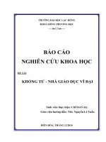
2.3.1 Building relative coordinate system qi at joints
Fig1. The relative coordinates q
i
We studied the absolute angles
θ
at joints in chapter 3 to synthesis the motion gait of the
biped robot. The nature of the biped control problem in this case is to control motors which
places at joints so that these joint rotate following a desired angle
θ
. Combining the controls of
these motors we get the motion gait of the biped robot. So we convert absolute coordinates
θ
to relative coordinates q, q is angle formed between directions of two links. This enables it is
easier to control biped robot.
We build the relative coordinate qi between joints as figure 1, qi is relative angle between
joint i+1 and i
Following the above method, we find out the relation between
i
q
and
i
θ
⎪
⎪
⎪
⎪
⎩
⎪
⎪
⎪
⎪
⎨
⎧
−=
−=
−−=
+−=
=
−=
−=
l
r
q
q
q
q
q
q
q
θ
θ
θθ
θθ
θ
θθ
θθ
7
6
545
34
0
4
33
211
211
360
180
(14)
Science & Technology Development, Vol 11, No.03- 2008
Trang 46
⎪
⎪
⎪
⎪
⎩
⎪
⎪
⎪
⎪
⎨
⎧
−=
−=
−−−=
+−=
=
+=
++=
7
6
5435
434
33
322
3211
180
180
q
q
qqq
q
qqq
l
r
θ
θ
θ
θ
θ
θ
θ
(15)
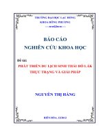
2.3.2 Some graphical results
With the coordinates qi calculated (14) we have some results as follow
(
4.3,130,5
21
===
pr
kkk
)
Fig2. The error of the 1st joint (degree/s)
Fig3. The error of the 2nd joint (degree/s)
Fig 4. The error of the 3th joint (degree/s)
Fig 5. The error of the 4th joint (degree/s)
TẠP CHÍ PHÁT TRIỂN KH&CN, TẬP 11, SỐ 03 - 2008
Trang 47
Fig 6. The error of the 5th joint (degree/s)
Fig 7. The error of the 6th joint (degree/s)
Fig 8. The error of the 7th joint (degree/s)
Fig 9. The demonstration of
2
ϕ
3.CONCLUSION
According to the demonstration in 2.2 section and the checked together the dynamic mode,
we get the quite good results of the error of each joint. However, it is necessary to combine
some more flexible control methods in the next research such as Neuron network and fuzzy
algorithm or other adaptive control models. The main reason to develop these control model
for the biped robot is that we simplified the problem, regardless of the effect of impact in
contact with the ground when the swing leg step forward in this research, in this case we have
to consider more the effect of the impulsive force from the ground when the swing leg starts
contacting with the ground. In addition, we should use some sensor devices (camera, loadcell)
in the next research so that we can build a humanoid robot with an artificial intelligence. So, it
is necessary to bring out flexible control model for the next research.
Science & Technology Development, Vol 11, No.03- 2008
Trang 48
MÔ PHỎNG ĐỘNG HỌC VÀ ĐIỀU KHIỂN ROBOT HAI CHÂN
Nguyễn Quốc Chí
(1)
, Dương Miên Ka
(1)
, Chung Tấn Lâm
(1)
, Lê Hoài Quốc
(2)
(1)Trường Đại học Bách khoa, ĐHQG-HCM
(2)
Sở Khoa học&Công nghệ Tp.HCM
TÓM TẮT: Trong bài báo này chúng tôi sẽ trình bày về một phương pháp điều khiển
cho mô hình phi tuyến robot biped 7 bậc tự do. Để sinh ra dáng đi cho robot, bài báo thực
hiện điều khiển vị trí của phần thân robot bám theo một quỹ đạo mong muốn dựa trên việc
phân tích động lực học của mô hình con lắc ngược 3D. Bài báo đưa ra một ràng buộc cho sự
di chuyển của con lặc ngược 3D đó là con lắc được di chuyển trên một mặt phẳng xác định.
Một thách thức lớn trong việc điều khiển di chuyển cho robot di chuyển hai chân đó là độ phi
tuyến cao của mô hình động lực học và các thông số không được chính xác trong mô hình của
robot.
REFERENCES
[1]. George Bekey et al, WTEC Panel Report, International Assessment of Research and
Development in Robotics, January, (2006).
[2]. F.L.Lewis, C.T.Abdallah, and D.M.Dawson, Control of Robotic Manipulators
Macmillan, (1993).
[3].
Nguyễn Đức Thành, Matlab và ứng dụng trong điều khiển, Nhà Xuất Bản Đại Học
Quốc Gia.
[4].
Miroslav Krstíc, Ioannis Kanellakopoulos, Petar Kokotovíc , Nonlinear and Adaptive
Control Design, John Wiley & Son, INC, (1995)
[5].
-K.S.Fu, R.C.Gonzalez, C.S.G. Lee, Robotics control, sensing, Vision, and
Intelligence (McGraw-Hill Book Co 1997)
[6].
Xiuping Mu, Dynamics and Motion Regulation of Five Link Biped Robot Walking in
the Sagittal Plane, PhD thesis (2004).