Báo cáo nghiên cứu khoa học: "Cảm biến tốc độ lâp động cơ cảm ứng trong bộ điều khiển trực tiếp mô-men xoắn"" pdf
Bạn đang xem bản rút gọn của tài liệu. Xem và tải ngay bản đầy đủ của tài liệu tại đây (371.42 KB, 7 trang )
TẠP CHÍ PHÁT TRIỂN KH&CN, TẬP 9, SỐ12 -2006
Trang 33
SENSORLESS SPEED ESTIMATION OF INDUCTION MOTOR IN A DIRECT
TORQUE CONTROL SYSTEM
Pham Dinh Truc
(1)
,Hoang Dang Khoa
(2)
(1) University of Technology, VNU-HCM
(2) Ho Chi Minh City University of Industry
(Manuscript Received on January 26
th
, 2006, Manuscript Revised December 04
th
, 2006)
ABSTRACT: Fast and robust torque control in a very wide range of speed is very needed
by various industrial AC drive applications. Therefore, since 1986 [1], direct torque control
(DTC) has been introduced to satisfy this desire. In order to achieve more economical control,
conventional speed sensor has been replacing by sensorless speed estimation. The sensorless
schemes are used to improve reliability and decrease maintenance requirements. In this paper,
concerned sensorless techniques of induction machine controlled by DTC algorithm are open-
loop estimators and MRAS schemes [2], [3]. To demonstrate clearly the advantages and
disadvantages between two kinds of sensorless techniques, obtained simulation results are
compared. By enhancing speed estimation, the pure integrator is replaced by a low-pass filter
to avoid DC drift and saturation problems [2].
Keywords: Sensorless, DTC (Direct Torque Control), IM (Induction Motor).
1. INTRODUCTION
Nowadays, comparing with the field oriented control (FOC), direct torque control (DTC) is
known as a simpler and easier scheme to perform [2], [4], [5]. With DTC technique, the
instantaneous values of flux and torque are estimated from the stator voltages and currents in
order to comparing with the command values. Residual results are used to determine the
optimum inverter switch states through a look-up table to supply for induction motor. As a
result, torque can be controlled directly.
The stator voltage being used for the estimation is obtained from DC link voltage the
switching states of the inverter (The inverter is assumed to be supplied from an ideal AC-DC
converter which takes AC voltage from the AC grid and provides the inverter a constant DC
input). The switching states of the inverter is controlled directly by the central processor,
therefore, the On-Off states of the transistors in the inverter are available to the processor. From
the pre-defined value of DC link voltage, the processor can determine the stator phase voltage
space vectors corresponding to those switching states. The stator phase currents are obtained
from current sensors.
In conventional speed control of DTC the actual value of rotor speed is required. The
controller receives the signals of rotor speed from the speed sensors. Unfortunately, the
accuracy of the control system will decrease with the appearance of noises, causing low
reliability. Furthermore, the conventional sensors make the higher cost, increase the complexity
of the systems because of noise filtering. The filtering will help to improve the quality of
feedback speed, however, additional digital filters require higher computing capacities for
faster signal processing and transmission. Therefore, they mount additional costs on the overall
systems.
Recently, many researches have been carried out for the design of speed sensorless control
schemes [2], [3]. In these new schemes the speed is obtained from the determined stator
voltages and measured stator currents instead of using a sensor. In this paper, two sensorless
techniques are presented, an open loop and a close-loop (MRAS) scheme, which can overcome
the necessity of the speed sensor.
Science & Technology Development, Vol 9, No.12 - 2006
Trang 34
This paper is organized as follows. First, DTC algorithm is introduced in Section 2. Then,
the proposed rotor speed estimation is presented in Section 3. In the Section 4, some simulation
results are presented. Finally, some concluding remarks are stated in the last Section.
2. THE DTC ALGORITHM
2.1 Dynamic Model of Induction Machine
All the equations in this paper are defined in stationary reference frame. Voltage and flux
equations:
dt
d
I.RU
S
S
S
S
S
S
S
ψ
+=
(1)
dt
d
.jI.R
S
R
S
R
R
S
R
R
ψ
+ψω−=
0 (2)
S
R
m
S
S
S
S
S
I.LI.L +=ψ
(3)
S
S
m
S
R
.R
S
R
I.LIL +=ψ (4)
Torque equations:
SR
mRS
m
e
)LL.L(
L
pT
ψ⊗ψ
−
=
2
2
3
(5)
dt
d
JTT
R
me
ω
=−
(6)
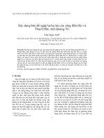
The symbol ⊗ in equation (5) denotes vector product. By using space vector theory, there
are eight voltage space vectors (six non-zero and two zero vectors) for an induction feeding by
a conventional voltage inverter [2], [4].
2.2 Synthesis of the Takahashi’s DTC Approach
In the equation (1), by neglecting the effect of stator voltage drop across stator resistance,
stator flux can be estimated directly from the stator voltage and the change of the stator flux
depends on the change of the stator voltage.
S
S
dt
d
ψ
≈
S
S
U (7)
By defining σ=(1-
RS
m
L.L
L
2
), T
R
=
R
R
R
L
and rearranging the equation from (1) to (4), a formula
of the rotor flux is obtained.
S
R
ψ =
σω−σ+ .T j.T.s
L
L
RRR
S
m
1
S
S
ψ (8)
Equation (8) implies that rotor flux is varied by the change of stator flux. Because of the
lager of rotor time constant (T
R
), rotor flux vector is assumed stationary during a small time
interval when stator flux vector is rotating. The torque value in the equation (5) can be
expressed in another way.
T
e
=
2
3
p.(
S
L.σ
1
)(
R
m
L
L
).
S
S
S
R
ψψ .sin(δ
S
-δ
R
) (9)
TẠP CHÍ PHÁT TRIỂN KH&CN, TẬP 9, SỐ12 -2006
Trang 35
From (7) to (9), it is important to note that, the torque of an induction machine is produced
by the interaction between rotor and stator flux space vectors. In a time interval small enough,
rotating of the stator flux space vector in appropriate direction, according to the demanded
torque, can result in a rapid and desirable changes of actual electromagnetic torque. It should be
emphasized that the suitable stator flux space vector will be obtained by using the optimized
inverter switching look-up table of Takahashi [1], [2], [5].
Figure 1.The changes of stator flux with the choosing switching states.
Table 1. The Takahashi’s optimized switching table.
Order
↑ T
e
↓ T
e
Not order T
e
↑ ψ
S
V
k+1
V
k-1
V
0,7
↓ ψ
S
V
k+2
V
k-2
V
0,7
3. THE SENSORLESS ESTIMATION TECHNIQUES
3.1 Open-loop speed estimation
The open-loop speed estimation is based on the residual between the speed of rotor flux and
the slip speed [2]. The scheme described below uses the monitored stator voltages and currents
to reconstruct the rotor flux, torque by equations from (1) to (5).
R
ω =
22
)()(
dt
d
dt
d
S
R
S
R
S
R
S
R
S
R
S
R
βα
αββα
ψ+ψ
ψψ−ψψ
-
p
R
R
3
2
||
S
R
ψ
1
T
e
(10)
This scheme requires several machine parameters, some of which vary with temperature,
skin effect and saturation. Thus, the speed can only be obtained accurately if these parameters
are accurately known.
3.2 Model Reference Adaptive System (MRAS)
In a MRAS system, rotor flux vector is estimated in a reference model, which is
independent of speed, and then compared with the one estimated by using an adaptive model,
which is using speed as a parameter. The reference and adaptive model are obtained by
rearranging the equations from (1) to (4).
Reference model equations:
Science & Technology Development, Vol 9, No.12 - 2006
Trang 36
S
R
ψ
=
m
R
L
L
[(
S
S
S
S
S
I.RU −
∫
)dt- σ.L
S
.
S
S
I
] (11)
Adaptive model equations:
S
R
ψ
= ]I.
T
L
) j
T
[(
S
S
R
m
S
R
R
R
∫
+ψω+−
1
dt (12)
Error betwen two model:
) ().Im(
S
R
S
R
S
R
S
R
S
R
S
R
β
α
α
β
∗
ω
ψψ−ψψ=ψψ=ε
(13)
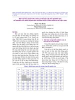
Figure 2. MRAS-based speed estimator scheme
The error between two models is the input of a PI control whose output is the estimated
rotor speed, this estimated speed is used to adjust the adaptive model until satisfactory
performance obtained [2], [4]. Since the MRAS is an close-loop system, the accuracy can be
increased. However, the models contain pure intergrators, which cause inaccuration of the
estimation system because of DC drift and saturation at the outputs of the intergrators. To avoid
the problem, low-pass filters are used.
4. SIMULATION RESULTS
Two sensorless high performance drives of induction machines using DTC are simulated,
one with open-loop speed estimator and one with closed loop MRAS speed estimator. Both
systems are simulated for the first two seconds, including acceleration during starting from zero
speed to rated speed, steady state at rated speed, and deceleration from rated speed to about 10
rad/s. Load rejection tests are carried out during steady states at rated speed as well as low
speed. These tests are aimed at investigating the disturbance rejection ability of the controller
by maintaining the actual speed at the commanded value of the controller when load suddenly
increases and decreases.
MATLAB/SIMULINK is used to carry out the simulations above. This software allows
digital simulation of the systems using analogue expression of the ordinary differential
equations in the dynamic machine model as well as the controller. The numerical method for
solving the equations is Runge-Kutta method. Fixed-step mode is chosen for the computational
time interval, this will emulate the fixed sampling frequency of the real-time control. The
sampling period is 1ìs. This sampling frequency is higher than the actual sampling frequency of
industrial DTC controllers, which is usually about 100kHz due to the limitation on the
switching frequencies of power electronic components. However, to verify the correctness of
TẠP CHÍ PHÁT TRIỂN KH&CN, TẬP 9, SỐ12 -2006
Trang 37
the suggested algorithms, highly accurate data is necessary. Nominal parameters for the test
motor are provided in Table 2.
Table 2. IM test motor parameters
Parameter Value
L
S
0.1459H
L
R
0.1490H
L
m
0.1410H
R
S
1.37Ω
R
R
1.1Ω
T
e
26.5Nm
J 0.1(kg.N/m)
P 2
U 240(V)
Flux Reference 0.9889Wb
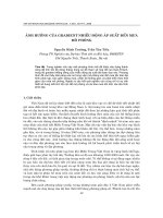
Figure 3. Reference load and speed Figure 4. Roror speed with the open-loop
estimation scheme.
Figure 5. Estimated Speed with the open-loop
estimation scheme at stabe state (Zoom F.4).
Figure 6.
Torque response with the open-loop
schem6
Science & Technology Development, Vol 9, No.12 - 2006
Trang 38
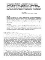
Figure 7. Roror speed with the MRAS estimation
scheme
Figure 8.
Transient of rotor speed when add and
remove load at high-speed
Figure 9. Estimation Speed with the MRAS
estimation scheme at stabilty state.
Figure 10.
Torque response with the MRAS
scheme.
Figure11.
Roror speed with the MRAS when replacing pure integrators by low-pass filters.
6. CONCLUSION
From the result above, the advantage and disadvantage between two schemes have been
analysed. Both open-loop and closed-loop scheme have good speed responses during loading or
TẠP CHÍ PHÁT TRIỂN KH&CN, TẬP 9, SỐ12 -2006
Trang 39
unloading, even at the low speed. The electromagnetic torque has fast responses because of the
advantage of DTC technique (figure 6 and figure 10).
It is significant that the closed-loop scheme is more accurate than the open-loop one due to
the presence of the PI controller in the closed-loop system that balances the ripper of rotor
speed.
One of concerned problem is the swiching frequency, the open-loop system requires higher
switching frequency than closed-loop scheme because of the lack of the PI controller (figure 5
and figure 9). This can be solved by using an Butterworth filter or other low-pass filter .
Both open and closed-loop schemes rely on the stability of machine parameters for a high
accuracy. Although the closed-loop estimator is sensitive to parameter fluctuation, it is still
effected by the variation of stator resistance due to thermal effect. To solve this problem, a
thermal model of induction machine should be concerned.
By replacing the pure integrator in the MRAS scheme with a low-pass filter, the practical
implementation will be more effective because of the elimination of DC drift and saturation
problems (figure 11).
ƯỚC LƯỢNG VẬN TỐC ĐỘNG CƠ KHÔNG DÙNG CẢM BIẾN TRONG HỆ
THỐNG ĐIỀU KHIỂN TRỰC TIẾP MOMENT
Phạm Đình Trực
(1)
, Hoàng Đăng Khoa
(2)
(1)Trường Đại học Bách khoa, ĐHQG-HCM
(2)Trường Đại học Công nghiệp Tp.HCM
TÓM TẮT: Bài báo trình bày các phương pháp ước lượng vận tốc dùng trong điều khiển
trực tiếp moment (DTC) của động cơ không đồng bộ. Hai nhóm phương pháp chủ yếu được
dùng là phương pháp ước lượng vận tốc mạch hở và phương pháp ước lượng vận tốc mạch hồi
tiếp. Điều khiển thích ứng mô hình được dùng trong phương pháp ước lượng vận tốc mạch hồi
tiếp. Đi
ều khiển thích ứng mô hình cho phép giảm tối thiểu ảnh hưởng của sai số cũng như sự
dao động của các giá trị tham số động cơ lên kết quả ước lượng vận tốc. Các kết quả mô phỏng
của hai phương pháp trên sẽ được so sánh. Để kết quả mô phỏng bám sát thực tế,các mạch tích
phân trong bộ điều khiển sẽ được thay thế bởi các mạch lọc t
ần số thấp trong các mô phỏng.
REFERENCES
[1]. I.Takahashi and T. Noguchi, A New Quick-Response and High-Efficiency Control
Strategy of an Induction Motor
, IEEE Trans.Ind Appl, Vol. IA-22, No.5, pp.820-827,
September, (1986).
[2].
P.Vas, Sensorless Vector and Direct Torque Control, Oxford University Press. pp.406-
559,
(1998).
[3]. P.Vas , Sensorless Drivers, State-of-Art. University of Aberdeen, (2002).
[4]. Bimal K.Bose, Modern Power Electronics and AC Drivers, Prentice Hall PTR.
pp.408-418, (2002).
[5].
Direct Torque Control- the world's most advanced AC drive technology, Technical
Guide No. 1,
ABB website.


![báo cáo nghiên cứu khoa học '''' vị trí khu di tích khảo cổ học 18 hoàng diệu trong cấu trúc thành thăng long - hà nội qua các thời kỳ lịch sử[1] ''''](https://media.store123doc.com/images/document/2014_06/29/medium_X3vWep7QoE.jpg)