Aluminium Design and Construction - Chapter 8 doc
Bạn đang xem bản rút gọn của tài liệu. Xem và tải ngay bản đầy đủ của tài liệu tại đây (534.88 KB, 33 trang )
CHAPTER 8
Beams
8.1 GENERAL APPROACH
This chapter covers the performance of aluminium beams under static
loading, for which the main requirement is strength (limit state of static
strength). In order to check this there are, as in steel, four basic failure
modes to consider:
1. bending-moment failure;
2. shear-force failure;
3. web crushing;
4. lateral-torsional (LT) buckling.
The resistance to bending failure (Section 8.2) must be adequate at any
cross-section along the beam, and likewise for shear force (Section 8.3).
When high moment and high shear act simultaneously at a cross-section,
it is important to allow for their combined effect (Section 8.4). The
possibility of web-crushing arises at load or reaction points, especially
when there is no web stiffener fitted (Section 8.5). Lateral-torsional
buckling becomes critical for deep narrow beams in which lateral supports
to the compression flange are widely spaced (Section 8.7).
In checking static strength, the basic requirement is that the relevant
factored resistance should not be less than the magnitude of the moment
or force arising under factored loading (Section 5.1.3). The factored
resistance is found by dividing the calculated resistance by the factor
?
m
. The main object of this chapter is to provide means for obtaining
the calculated resistance corresponding to the various possible modes
of static failure. The suffix c is used to indicate ‘calculated resistance’.
When a member is required to carry simultaneous bending and axial
load, it is obviously necessary to allow for interaction of the two effects.
This is treated separately at the end of Chapter 9.
For aluminium beams, it is also important to consider deflection
(serviceability limit state) bearing in mind the metal’s low modulus.
This is a matter of ensuring that the elastic deflection under nominal
loading (unfactored service loading) does not exceed the permitted value
(Section 8.8).
Copyright 1999 by Taylor & Francis Group. All Rights Reserved.
8.2 MOMENT RESISTANCE OF THE CROSS-SECTION
8.2.1 Moment-curvature relation
In this section we consider resistance to bending moment. The object
is to determine the calculated moment resistance M
c
of the cross-section,
i.e. its failure moment.
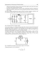
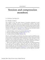
Figure 8.1 compares the relation between bending moment and
curvature for a steel universal beam of fully-compact section and an
extruded aluminium beam of the same section. It is assumed that the
limiting stress p
°
is the same for each, this being equal to the yield stress
and the 0.2% proof stress respectively for the two materials. Typically,
the diagram might be looked on as comparing mild steel and 6082-T6
aluminium.
Moment levels Zp
°
and Sp
°
are marked on the diagram, where Z and
S are the elastic and plastic section moduli respectively. Both curves
begin to deviate from linear at a moment below Zp
°
. This happens in
steel, despite the well-defined yield point of the material, because of
the severe residual stresses that are locked into all steel profiles. For the
aluminium, it is mainly a function of the rounded knee on the stress-
strain curve.
The problem in aluminium is how to decide on an appropriate value
for the limiting moment, i.e. the calculated moment resistance (M
c
).
This is the level of moment corresponding to ‘failure’ of the cross-
section, at which severe plastic deformation is deemed to occur. For a
steel beam, there is an obvious level at which to take this, namely at the
‘fully plastic moment’ Sp
°
where the curve temporarily flattens out. In
aluminium, although there is no such plateau, it is convenient to take
the same value as for steel, namely M
c
=Sp
°
. That is what BS.8118 does
and we follow suit in this book (for fully compact sections). F.M.Mazzolani
has proposed a more sophisticated treatment [26].
Figure 8.1 Comparison of the curves relating bending moment M and curvature 1/R for
steel (1) and aluminium (2) beams of the same section and yield/proof stress.
Copyright 1999 by Taylor & Francis Group. All Rights Reserved.
8.2.2 Section classification
The discussion in Section 8.2.1 relates to beams that are thick enough
for local buckling not to be a factor. We refer to these as fully compact.
For thinner beams (semi-compact or slender) premature failure occurs
due to local buckling of plate elements within the section, causing a
decrease in M
c
below the ideal value Sp
°
.
The first step in determining M
c
is to classify the section in terms of
its susceptibility to local buckling (see Chapter 7). To do this the
slenderness ß (=b/t or d
c
/t) must be calculated for any individual plate
element of the section that is wholly or partly in compression, i.e. for
elements forming the compression flange and the web. Each such element
is then classified as fully compact, semi-compact or slender by comparing
its ß with the limiting values ß
f
and ß
s
as explained in Section 7.1.4.
The least favourable element classification then dictates the classification
of the section as a whole. Thus, in order for the section to be classed as
fully compact, all the compressed or partly compressed elements within
it must themselves be fully compact. If a section contains just one slender
element, then the overall section must be treated as slender. The
classification is unaffected by the presence of any HAZ material.
In classifying an element under strain gradient, the parameter ? (Section
7.3) should relate to the neutral axis position for the gross section. In
checking whether the section is fully compact, this should be the plastic
(equal area) neutral axis, while for a semi-compact check it should be
the elastic neutral axis (through the centroid).
8.2.3 Uniaxial moment, basic formulae
First we consider cases when the moment is applied either about an
axis of symmetry, or in the plane of such an axis, known as symmetric
bending (Figure 8.2). For these the calculated moment resistance M
c
of
the section is normally taken as follows:
Fully compact section M
c
=Sp
°
(8.1)
Semi-compact or slender section M
c
=Zp
°
(8.2)
where p
°
=limiting stress for the material (Section 5.2), S=plastic section
modulus, and Z=elastic section modulus. By using these formulae we
Figure 8.2 Symmetric bending.
Copyright 1999 by Taylor & Francis Group. All Rights Reserved.
are effectively assuming idealized stress patterns (fully plastic or elastic),
based on an elastic-perfectly plastic steel-type stress-strain curve. The
effect, that the actual rounded nature of the stress-strain curve has on
the moment capacity, is considered by Mazzolani in his book Aluminium
Alloy Structures [26].
For a non-slender section, non-welded and without holes, the modulus
S or Z is based on the actual gross cross-section. Otherwise, it should be
found using the effective section (Section 8.2.4). Chapter 10 gives guidance
on the calculation of these section properties.
8.2.4 Effective section
The moment resistance of the cross-section must when necessary be
based on an effective section rather than the gross section, so as to
allow for HAZ softening at welds, local buckling of slender plate elements
or the presence of holes:
1. HAZ softening. In order to allow for the softening at a welded joint,
we assume that there is a uniformly weakened zone of nominal area
A
z
beyond which full parent properties apply. One method is to take
a reduced thickness k
z
t in this zone and calculate the modulus
accordingly, the appropriate value for the softening factor k
z
being
k
z2
. Alternatively the designer can assume that there is a ‘lost area’
of A
z
(1-k
z
) at each HAZ, and make a suitable deduction from the
value obtained for the modulus with HAZ softening ignored. Refer
to Section 6.6.1.
2. Local buckling. For a slender plate element, it is assumed that there
is a block of effective area adjacent to each connected edge, the rest
of the element being ineffective (Chapter 7). For a very slender outstand
element (Section 7.2.5), as might occur in an I-beam compression
flange, it is permissible to take advantage of post-buckled strength
when finding the moment resistance of the cross-section, rather than
use the reduced effective width corresponding to initial buckling.
3. Holes. The presence of a small hole is normally allowed for by removing
an area dt from the section, where d is the hole diameter, although
filled holes on the compression side can be ignored. However, for a
hole in the HAZ, the deduction need be only k
z
dt, while for one in
the ineffective region of a slender element none is required.
In dealing with the local buckling of slender elements under strain gradient,
as in webs, it is normal for convenience to base the parameter
(Section
7.3) on the neutral axis for the gross section, and obtain the widths of the
effective stress-blocks accordingly. However, in then going on to calculate
the effective section properties (I, Z), it is essential to use the neutral axis
of the effective section, which will be at a slightly different position from
Copyright 1999 by Taylor & Francis Group. All Rights Reserved.
that for the gross section. It would in theory be more accurate to adopt
an iterative procedure, with
adjusted according to the centroid position
of the effective section, although in practice nobody does so.
For a beam containing welded transverse stiffeners, two alternative
effective sections should be considered. One is taken mid-way between
stiffeners, allowing for buckling. The other is taken at the stiffener position
with HAZ softening allowed for, but buckling ignored.
8.2.5 Hybrid sections
It is possible for aluminium beams to be fabricated from components of
differing strength, as for example when 6082-T6 flanges are welded to
a 5154A-H24 web. The safe but pessimistic procedure for such a hybrid
section is to base design on the lowest value of p
°
within the section.
Alternatively, one can classify the section taking the true value of p
°
for
each element, and then proceed as follows:
1. Fully compact section. Conventional plastic bending theory is used,
M
c
being based on an idealized stress pattern, in which due account
is taken of the differing values of p
°
.
2. Other sections. Alternative values for M
c
are found, of which the lower
is then taken. One value is obtained using equation (8.2) based on p
°
for the extreme fibre material. The other is found as follows:
(8.3)
where I=second moment of area of effective section, y=distance from
neutral axis thereof to the edge of the web, or to another critical
point in a weaker element of the section, p
°
=limiting stress for the
web or other weaker element considered.
8.2.6 Use of interpolation for semi-compact sections
Consider the typical section shown in Figure 8.3, when the critical element
X is just semi-compact (ß=ß
s
). In such a case, equation (8.2) gives a good
Figure 8.3 Interpolation method for semi-compact beam, idealized stress-patterns.
Copyright 1999 by Taylor & Francis Group. All Rights Reserved.
estimate for the resistance M
c
of the section, since element X can just
reach a stress p
°
before it buckles. Line 1 in the figure, on which equation
(8.2) is based, approximately represents the stress pattern for this case
when failure is imminent. (We say ‘approximately’ because it ignores
the rounded knee on the stress-strain curve.)
Now consider semi-compact sections generally, again taking the type
of beam in Figure 8.3 as an example. For these, the critical element X
will have a ß-value somewhere between ß
f
and ß
s
, and some degree of
plastic straining can therefore take place before failure occurs. This
leads to an elasto-plastic stress pattern at failure such as line 2 in the
figure, corresponding to a bending moment in excess of the value Zp
°
.
In the extreme case when element X is almost fully compact (ß only just
greater than ß
f
) the stress pattern at failure approaches line 3,
corresponding to an ultimate moment equal to the fully compact value
Sp
°
which can be as much as 15% above that based on Z. It is thus seen
that the use of the value Zp
°
tends to underestimate M
c
, increasingly so
as ß for the critical element approaches ß
f
.
It is therefore suggested that interpolation should be used for semi-
compact sections, with M
c
found as follows:
(8.4)
This expression, in which the ß’s refer to the critical element, will produce
higher values of M
c
closer to the true behaviour.
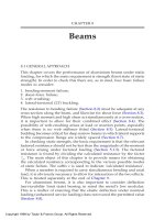
8.2.7 Semi-compact section with tongue plates
Figure 8.4 shows a section with tongue plates, in which the d/t of the web
(between tongues) is such as to make it semi-compact when classified in
Figure 8.4 Elastic-plastic method for beam with tongue plates.
Copyright 1999 by Taylor & Francis Group. All Rights Reserved.
the usual manner. Line 1 in the figure indicates the (idealized) stress
pattern on which M
c
would be normally based, corresponding to
expression (8.2). Clearly this fails to utilise the full capacity of the web,
since the stress at its top edge is well below the value p
°
it can attain
before buckling. Equation (8.2) therefore underestimates M
c
.
An improved result may be obtained by employing an elasto-plastic
treatment, in which a more favourable stress pattern is assumed with
yield penetrating to the top of the web (line 2). The moment calculation
is then based on line 2 instead of line 1. If the web is only just semi-
compact, M
c
is taken equal to the value M
c2
calculated directly from line
2, while, in the general semi-compact case, it is obtained by interpolation
using equation (8.4), with the quantity Zp
°
replaced by M
c2
.
When operating this method we allow for HAZ softening by using
the gross section and reducing the stress in any HAZ region to k
z2
p
°
.
8.2.8 Local buckling in an understressed compression flange
Figure 8.5 shows a type of section in which the distance y
c
from the
neutral axis to a slender compression flange X is less than the distance
y
t
to the tension face. For such sections, local buckling in the compression
flange becomes less critical because it is ‘understressed’, and the normal
method of calculation will produce an oversafe estimate of M
c
. An
improved result can be obtained by replacing the parameter (= (250/
p
°
)) in the local buckling calculations by a modified value ’ given by:
(8.5)
This may make it possible to re-classify the section as semi-compact, or,
if it is still slender, a more favourable effective section will result. In
either case, M
c
is increased.
Note, however, that such a device should not be employed as a
means for upgrading a section from semi-compact to fully compact.
8.2.9 Biaxial moment
We now turn to the case of asymmetric bending, when the applied
moment has components about both the principal axes of the section.
Figure 8.5 Understressed compression flange (X).
Copyright 1999 by Taylor & Francis Group. All Rights Reserved.
Examples of this are shown in Figure 8.6:
(a, b) bisymmetric or monosymmetric section with inclined moment;
(c) skew-symmetric section;
(d) asymmetric section.
For (a) and (b), the essential difference from symmetric bending is that
the neutral axis (axis of zero stress) no longer coincides with the axis
mm of the applied moment M. The same applies to (c) and (d), unless
mm happens to coincide with a principal axis of the section. Also, for
any given inclination of mm the plastic and elastic neutral axes will be
orientated differently.
In classifying the section, the parameter
for any element under
strain gradient should be based on the appropriate neutral axis, which
properly relates to the inclination of mm. This should be the plastic
neutral axis for the fully-compact check (Section 10.2.2), or the elastic
one for the semi-compact check (see 2 below).
Having classified the cross-section, a simple procedure is then to use
an interaction formula, such as that given in BS.8118, which for
bisymmetric and monosymmetric sections may be written:
(8.6)
where: M=moment arising under factored loading,
=inclination of mm (figure 8.6),
M
cx
, M
cy
=moment resistance for bending about Gx or Gy,
m
=material factor (see 5.1.3).
This expression may also be used for skew-symmetric and asymmetric
profiles, changing x, y to u, v. It gives sensible results when applied to
semi-compact and slender sections of conventional form (I-section,
channel), but can be pessimistic if the profile is non-standard. In order
to achieve better economy in such cases, the designer may, if desired,
proceed as follows.
Figure 8.6 Asymmetric bending cases.
Copyright 1999 by Taylor & Francis Group. All Rights Reserved.
1. Fully compact sections. The limiting value of M is found using expression
(8.1) with the plastic modulus S replaced by a value S
m
which is a
function of the inclination of mm (angle ). Refer to Section 10.2.2.
2. Semi-compact and slender sections. The applied moment M is resolved
into components M cos and M sin about the principal axes, the
effects of which are superposed elastically. A critical point Q is chosen
and the section is adequate if at this position (Figure 8.6(a))
(8.7)
where x, y are the coordinates of Q, the I’s are for the effective
section, and the left-hand side is taken positive. The inclination of
the neutral axis nn (anti-clockwise from Gx) is given by:
(8.8)
The same expressions are valid for skew-symmetric and asymmetric
shapes, if x, y are changed to u, v. Sometimes the critical point Q is
not obvious, in which case alternative calculations must be made for
possible locations thereof and the worst result taken. It is obviously
important to take account of the signs of the stresses for flexure
about the two axes.
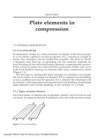
Figure 8.7 gives a comparison between predictions made with the simple
British Standard rule (expression (8.6)) and those obtained using the
more accurate treatments given in 1 and 2 above. The figure relates to a
particular form of extruded shape and shows how the limiting M varies
Figure 8.7 Asymmetric bending example. Comparison between BS 8118 and the more
rigorous treatment of Section 8.2.9, covering the fully-compact case (FC) and the semi-
compact case (SC).
Copyright 1999 by Taylor & Francis Group. All Rights Reserved.
with . It is seen that the predicted value based on expression (8.6) can
be as much as 36% too low for the fully compact case and 39% too low
for semi-compact.
8.3 SHEAR FORCE RESISTANCE
8.3.1 Necessary checks
We now consider the resistance of the section to shear force, for which
two types of failure must be considered: (a) yielding in shear; and (b)
shear buckling of the web. Procedures are presented for determining the
calculated shear force resistance V
c
corresponding to each of these cases.
The resistance of a thin web to shear buckling can be improved by
fitting transverse stiffeners, unlike the moment resistance. This makes
it difficult to provide a general rule for classifying shear webs as compact
or slender. However, for simple I, channel and box-section beams, having
unwelded webs of uniform thickness, it will be found that shear buckling
is never critical when d/t is less than 750/ p
o
where p
o
is in N/mm
2
.
Stiffened shear webs can be designed to be non-buckling at a higher d/
t than this.
8.3.2 Shear yielding of webs, method 1
Structural sections susceptible to shear failure typically contain thin
vertical webs (internal elements) to carry the shear force. Alternative
methods 1 and 2 are offered for obtaining the calculated resistance V
c
of these, based on yield. In method 1, which is the simpler, V
c
is found
from the following expression:
V
c
=0.8Dt
1
P
v
(8.9)
where D=overall depth of section, t
1
=critical thickness, and p
v
=limiting
stress for the material in shear (Section 5.2). In effect, we are assuming
that the shear force is being carried by a thin vertical rectangle of depth
D and thickness t
1
with an 80% efficiency.
For an unwelded web, t
1
is simply taken as the web thickness t or the
sum of the web thicknesses in a multi-web section. If the thickness
varies down the depth of the web, t
1
is the minimum thickness. When
there is welding on the web, t
1
=k
z1
t where k
z1
is the HAZ softening
factor (Section 6.4).
8.3.3 Shear yielding of webs, method 2
The alternative method 2 produces a more realistic estimate of V
c
which
is generally higher than that given by method 1. It considers two possible
Copyright 1999 by Taylor & Francis Group. All Rights Reserved.
patterns of yielding, corresponding to the two kinds of complementary
stress that act in a web, namely transverse shear and longitudinal shear.
Figure 8.8 depicts the two patterns. Transverse yielding would typically
govern for a web containing a full depth vertical weld; while longitudinal
yield might be critical along the line of a web-to-flange weld. (Method
1 automatically covered both patterns, conservatively.)
Method 2 employs expressions (8.10) and (8.11) for obtaining V
c
, the
lower value being taken. Equation (8.10) relates to yielding on a specific
cross-section, and equation (8.11) to yielding on a longitudinal line at
a specific distance y
v
from the neutral axis.
Transverse yield V
c
=A
w
p
v
(8.10)
(8.11)
where: A
w
=effective section area of web,
I=inertia of the section,
t
2
=relevant thickness,
(Ay¯)=first moment of ‘excluded area’,
K=1.1 (but see discussion below),
p
v
=limiting stress for the material in shear.
A
w
is taken as the effective area of all vertical material up to the face
of each flange, as shown in Figure 8.9(a). Tongue plates are included
but any horizontal fins are not. An effective thickness equal to k
z1
t must
be assumed for any HAZ material in the web cross-section considered,
where t is the actual thickness.
Figure 8.8 Transverse and longitudinal yield in a shear web.
Figure 8.9 Shear force resistance, method 2. Definitions.
Copyright 1999 by Taylor & Francis Group. All Rights Reserved.
(Ay¯) and t
2
relate to the given point W in the web at which the longitudinal
yield is being checked. Typically this point, defined by y
v
, will be located
in one of the following critical positions:
1. at the neutral axis (y
v
=0);
2. at the inmost point of a region of actual reduced thickness;
3. at the inmost point of a region of HAZ softening (reduced effective
thickness).
In cases 1 and 2 we put t
2
equal to the actual web thickness t at the
point considered, while in case 3 we put it equal to k
z1
t. In a multi-web
beam, t
2
should be summed for all the webs. (Ay¯) is the first moment
of area about the neutral axis of all the material in the cross-section
lying beyond point W, shown shaded in Figure 8.9(b).
I and (Ay¯) may for convenience both be based on the gross section.
Alternatively they may both be based on the effective section as used
in checking the moment.
The factor K in equation (8.11) needs consideration. If it were put
equal to 1.0, this would imply that the member fails as soon as the
longitudinal shear stress in the web reaches yield at the critical point,
which is a pessimistic assumption. It would be more realistic to permit
the area of yielding to spread slightly, and thereby allow a higher V
c
.
We suggest that the designer should achieve this by putting K=1.1 instead
of 1.0. For an ordinary unwelded I-beam, this value leads to an answer
roughly equal to the method 1 value, which corresponds to the typical
treatment in steel codes.
The above procedure for obtaining V
c
deviates from that given in
BS.8118, which appears to contain inconsistencies and shortcomings.
The main point at issue concerns unwelded webs, for which the British
Standard requires only the transverse check to be made. When such a
web contains a region of reduced thickness, such as thin web material
located between tongue plates, longitudinal yielding becomes critical.
But BS.8118 calls for the longitudinal check only if there are longitudinal
welds present, i.e. only for position 3. Our treatment requires it to be
made for position 2 also. For an extruded I-section (unwelded) with
tongue plates, it is possible for BS.8118 to over-estimate V
c
by 40%, as
compared with the procedure advocated above.
In applying method 2 to a hybrid section, the procedure may be
modified in the following manner:
1. Transverse check. Equation (8.10) is used with p
v
taken as that for the
weaker material. Alternatively, the designer may take V
c
equal to the
summation of A
e
p
v
for the various parts of the web, where A
e
is the
effective area of each and p
v
the relevant material stress.
2. Longitudinal check. Equation (8.11) should be used with p
v
put equal
to the relevant value at the point W.
Copyright 1999 by Taylor & Francis Group. All Rights Reserved.
8.3.4 Shear resistance of bars and outstands
The shear force resistance V
c
of a rectangular bar may be estimated
using equation (8.9), with t
1
put equal to the section width. An equivalent
expression may be employed for round bar or tube, replacing Dt
1
by
the section area A.
When the shear force is carried by a vertical outstand element (or
outstands), as in a T-bar or a channel loaded about its weak axis, V
c
may
be generally found by treating the outstand as a rectangular bar (as
above). However, if the outstand is too slender in cross-section, its shear
force resistance will be reduced by buckling. In the absence of hard data,
a possible approach is to assume that the full value of V
c
(based on yield)
can be attained, provided the depth/thickness ratio does not exceed the
limiting value ß
s
based on uniform compression (Table 7.1). If this value
is exceeded, V
c
is determined as if the extra material were not there.
8.3.5 Web buckling, simple method
The treatments given below apply to thin internal elements used as
shear webs, as in an I-beam. A safe way to check for possible buckling
failure in these is simply to base V
c
on the initial buckling stress, and
to neglect any post-buckled reserve of strength. For a plain web of
uniform thickness (Figure 8.10(a)) this gives a value as follows:
V
c
=dtp
v1
(8.12)
where d=depth of web between flanges, t=web thickness, p
v1
=initial
buckling stress in N/mm
2
.
For an unstiffened web p
v1
may be found from the following expression,
which assumes simple support along the top and bottom edges:
(8.13)
where E is the modulus of elasticity (=70 kN/mm
2
).
Figure 8.10 Shear buckling, web dimensions.
Copyright 1999 by Taylor & Francis Group. All Rights Reserved.
When transverse stiffeners are fitted, an improved value of p
v1
may
be read from Figure 8.11, in which a is the stiffener spacing. Alternatively
the designer may use the equations on which the figure is based:
(8.14a)
(8.14b)
For a web fitted with tongue plate or plates (Figure 8.10(b)), it is necessary
to sum the web and tongue contributions. This may be done as follows,
provided the tongue plates are properly designed (Section 8.6.2):
V
c
=V
cw
+V
ct
(8.15)
where: V
cw
=value given by (8.12) taking d as the depth between tongues,
V
ct
=Σ A
t
p
vt
A
t
=total effective area of tongue plates,
p
vt
=limiting stress in shear for tongue material.
In a multi-web beam, V
c
may be taken as the sum of the values found
for the individual webs, using expression (8.12) or (8.15) as appropriate.
8.3.6 Web buckling, tension-field action
Very slender stiffened webs can often accept a great increase in shear
force above the initial buckling load before they finally fail. This results
from the development of a diagonal tension field as the buckles develop
(Figure 8.12). The designer can take advantage of this by using the treatment
below, based on the ‘Cardiff model’ of Rockey and Evans [15], which
Figure 8.11 Shear buckling stress for stiffened webs (without tension-field action).
Copyright 1999 by Taylor & Francis Group. All Rights Reserved.
is valid when 2.5 > a/d > 0.5. However, if the presence of visible buckles
at working load is unacceptable, V
c
must be found in the usual way as
in Section 8.3.5, with tension-field action ignored.
In any given panel between transverse stiffeners, it is only possible
for the tension field to develop if it is properly anchored at either end,
i.e. if there is something for it to pull against. In an internal panel, such
as I in the figure, anchorage is automatically provided by the adjacent
panels. But in an end panel (E) there is generally nothing substantial
for a tension field to pull on and the tension field cannot develop. Only
if a proper ‘end-post’ (EP) is provided, designed as in Section 8.6.4, can
effective tension-field action in an end-panel be assumed.
The value of V
c
based on tension-field action is found as follows for
a plain web (Figure 8.10(a)):
V
c
=dt{p
v1
+k(v
2
+mv
3
)p
v
} (8.16)
where d, t=web depth and thickness; p
v
=limiting stress in shear; p
v1
=initial
buckling stress (Section 8.3.5); m=lesser of m
1
and m
2
; k=k
z1
for welded
webs or 1.0 for other webs;
S
f
is plastic modulus of effective flange section about its own horizontal
equal area axis, taken as the lower value when the flanges differ. In a
hybrid beam the expression for m
2
should be multiplied by the square-
root of the ratio of p
o
for the flange material to p
o
for the web.
For a web with properly designed tongue-plates V
c
may be found
using equation (8.15), with V
cw
now taken as the value of V
c
that would
be obtained from expression (8.16) putting d equal to the web plate
depth between tongues. When determining S
f
it is permissible to include
the tongue plate as an integral part of the flange.
In a multi-web beam, V
c
is again taken as the sum of the values for
the individual webs. In finding m
2
, the quantity S
f
should be shared
between the webs.
Figure 8.12 Tension-field action.
Copyright 1999 by Taylor & Francis Group. All Rights Reserved.
8.3.7 Inclined webs
For a beam with inclined webs, as in Figure 8.13, the various expressions
for obtaining the shear force resistance of the section need to be adapted
as follows:
1. Yield check, method 1. Equation (8.9) remains valid taking D as the
overall section depth, t
1
is based on the actual metal thickness t, or
k
z1
t if welded.
2. Yield check, method 2. Expressions (8.10) and (8.11) for V
c
should be
multiplied by cos , where is the angle of inclination of the webs,
and t
2
is the actual metal thickness (or the effective thickness if welded).
3. Buckling check. Expression (8.12) or (8.16) for finding V
c
should be
multiplied by cos . In either expression, the depth d of the web
plate is measured on the slope, and t is the actual metal thickness.
Also d and t are defined in this way when obtaining p
v1
, v
2
, v
3
, or m
1
It is necessary to multiply S
f
by cos when calculating m
2
.
4. Web with tongue plates. In applying equation (8.15), the expression
defining V
ct
should be multiplied by cos .
8.4 COMBINED MOMENT AND SHEAR
8.4.1 Low shear
At any given cross-section of a beam, it is usually found that moment
and shear force act simultaneously. Obviously the designer must consider
possible interaction between the two effects. In most beams, the moment
is the critical factor, and the problem is to find whether or by how
much the moment resistance is eroded by the presence of the shear.
If the applied shear force is reasonably small, the effect on the moment
resistance is negligible and can be ignored. This is referred to as the
‘low shear’ case, and can be assumed to apply when the shear force V
arising under factored loading does not exceed half the factored shear
force resistance V
c
/
m
without moment.
Figure 8.13 Beam with inclined shear webs.
Copyright 1999 by Taylor & Francis Group. All Rights Reserved.
8.4.2 High shear, method A
For the ‘high shear’ case (V > 0.5V
c
/
m
), the moment resistance must be
suitably reduced to allow for the coexistent shear force. One method is
to use a simple interaction diagram of the form shown in Figure 8.14(a),
which gives the reduction in M
c
as a function of V. In entering this, M
co
is taken as the calculated moment resistance in the absence of shear.
Such a diagram gives a reasonable result for solid bars (for which shear
force is seldom a factor anyway), but is over-safe for typical beams
containing thin webs.
8.4.3 High shear, method B
Figure 8.14(b) shows a more favourable form of interaction diagram,
from which the reduced M
c
may generally be found for members in
which the shear is carried by webs. In entering this figure, M
co
is again
the value of M
c
without shear, while M
cf
is that part of M
co
which is
contributed by the flanges with web (and tongue plates) excluded.
When tension-field action has been included in the determination of
V
c
, Figure 8.14(b) becomes invalid and a diagram of the form shown in
Figure 8.14 (c) should be employed instead. In this, we take V
cw
as the
value of V
c
that would be obtained by putting m=0 in equation (8.16).
8.5 WEB CRUSHING
8.5.1 Webs with bearing stiffeners
At any position where a concentrated load or reaction acts on a beam,
it is obviously desirable to provide a properly designed transverse stiffener,
to prevent crushing of the web. The design of such stiffeners, known as
‘bearing stiffeners’, is covered in Section 8.6.3 below.
Figure 8.14 Moment/shear interaction: (a) method A; (b) method B; (c) with tension-field
action.
Copyright 1999 by Taylor & Francis Group. All Rights Reserved.
8.5.2 Crushing of unstiffened webs
In the absence of a bearing stiffener, either for economy or because of a
rolling load (Figure 8.15), it is necessary to consider the possibility of
localized web crushing. The designer must determine the calculated
resistance W
c
to such failure, and ensure that this is not less than
m
times
the factored load W acting at the point considered, where W is the nominal
(working) load or reaction at that point multiplied by
f
. The BS.8118
procedure for finding W
c
is to obtain two values, based on yield and on
buckling, and take the lower. Both assume a 45° dispersion angle.
1. Yield failure. The critical position for this will typically be either adjacent
to the flange or adjacent to a tongue-plate. For any given position,
W
c
may be calculated using the expression:
W
c
=ct
w
P
a
(8.17)
where: c=width of dispersion zone at the level considered,
t
w
=actual metal thickness t at that level, if unwelded,
=k
z1
t in an HAZ region,
k
z1
=HAZ softening factor (Section 6.4),
p
a
=limiting stress for the material.
If necessary, W
c
should be calculated at two or more levels, and the
lowest value taken.
2. Buckling failure. For this, it is assumed that the load is carried by a
vertical strip of the web acting as a strut, with cross-section c
°
t where
c
°
is the value of c at the neutral axis. W
c
is found thus:
W
c
=c
°
tp
b
(8.18)
where t=actual web thickness, and p
b
=limiting stress based on column
buckling of the assumed strip. p
b
may be read from a type C1 buckling
curve defined by p
1
=p
°
(Section 9.5.2), taking the slenderness as
follows:
= (d/t) (8.19)
where d is the web-plate depth between flanges or tongue plates if
fitted. When the loaded flange is held from out-of plane movement
relative to the other flange, may be taken in the range 2.5–3.5,
Figure 8.15 Web crushing.
Copyright 1999 by Taylor & Francis Group. All Rights Reserved.
depending on the estimated degree of rotational restraint at the ends
of the assumed strut. A value of =3.5 would correspond to pinned
ends. If however the loaded flange is free to deflect laterally as the
web buckles, should be suitably increased.
In a multi-web beam, W
c
should be summed for all the webs. If the
webs are inclined (Figure 8.13), the values of W
c
given by equations
(8.18) must be multiplied by cos , with the web-plate depth d measured
on the slope.
8.6 WEB REINFORCEMENT
8.6.1 Types of reinforcement
The following types of reinforcement may be used for strengthening
the webs of beams:
1. tongue plates;
2. bearing stiffeners (transverse);
3. intermediate stiffeners (transverse);
4. end-posts.
To be effective, these must be properly designed, the rules given below
being based on BS.8118.
8.6.2 Tongue plates
The provision of tongue plates (Figure 8.16) can be beneficial in various
ways. It enables web-to-flange welds to be moved in from the extreme
fibres, thereby locating the HAZ in a region of lower stress. It reduces
the d/t ratio of the web, thus improving the buckling performance in
both bending and shear. Also, when a rolling load has to be carried on
the top flange, it greatly increases the resistance to web crushing.
To be effective, a tongue should be proportioned so as not to be slender
in terms of local buckling. A safe rule is to make the ratio of its depth b
t
Figure 8.16 Tongue dimensions.
Copyright 1999 by Taylor & Francis Group. All Rights Reserved.
to its thickness t
t
such that it would be classed as compact when considered
as an outstand element under uniform longitudinal compression:
(8.20)
8.6.3 Transverse stiffeners
Transverse web stiffeners may be one or other of two basic kinds:
• Bearing stiffeners are provided at points of concentrated load or reaction,
to resist crushing;
• Intermediate stiffeners are fitted at intervals along the span, to divide
the web into smaller panels and improve its resistance to shear buckling.
The stiffeners can be single or double-sided. They are often in the form
of simple fins or outstands. Alternatively they can comprise channels
applied in such a way as to create a closed section. When of the former
type (a) the stiffener section (b
s
×t
s
) should be such that it would be
classed as compact when considered as an outstand element under
compression (Section 7.1.4):
(8.21)
Transverse stiffeners must be designed to meet a strength requirement
and also, generally, a stiffness requirement. In checking either of these,
it is permissible to include an associated width of web-plate as part of
the effective stiff ener section, extending a distance b
1
each side of the
actual stiffener (Figure 8.18), generally given by:
b
1
=lesser of 0.13a and 15 t (8.22)
Figure 8.17 Transverse web stiffeners: bearing (B) and intermediate (I).
Figure 8.18 Transverse web stiffener, effective section (plan view).
Copyright 1999 by Taylor & Francis Group. All Rights Reserved.
where a is the stiffener spacing and t the web thickness. At the outboard
side of an end stiffener, it should be taken as the lesser of a
o
and 6et
where a
o
is the distance to the free edge of the web.
(a) Strength
The effective stiffener is checked as a strut, buckling out of the plane of the
web, which is required to carry a notional load P under factored loading.
Bearing stiffener P=W+V/3 (8.23a)
Intermediate stiffener P=V/3 (8.23b)
where W=factored load or reaction applied to the beam at the stiffener
considered, and V=average shear force arising in the panels either side
of the stiffener, under factored loading.
The effective stiffener section, including the associated width of web
plate, must be such that its calculated resistance P
c
to column buckling
about an axis parallel to the web is not less than
m
P. P
c
may be found as
in Section 9.5, with suitable allowance for any HAZ softening within the
effective section, and taking an effective strut length l generally as follows:
a/d у 1.5 l=d (8.24)
(8.25)
where d is the depth of the web plate between flanges or tongue plates,
if fitted. When the panel dimension is different on the two sides of the
stiffener, a should be taken as the mean value. If the applied load W
acts eccentric to the axis of the stiffener, due account should be taken
of the moment thereby introduced (combined axial load and moment).
(b) Stiffness
When a is less than 2.9d, the following requirement should also be satisfied:
(8.26)
where I
s
=inertia of the effective stiffener section, including the associated
part of the web, about an axis through its centroid parallel to the web,
with HAZ softening ignored.
8.6.4 End-posts
An ‘end-post’ is a special kind of transverse web stiffener that may be
needed at the ends of a deep slender beam: (a) to provide twist resistance
Copyright 1999 by Taylor & Francis Group. All Rights Reserved.
at that point, and/or (b) to anchor a tension field in the end panel of
the web. These functions are in addition to the normal one of acting as
a bearing stiffener to resist the reaction force. An end-post should be
double-sided, with stiffening material added symmetrically either side
of the web. It should extend the full depth between flanges.
(a) Twist resistance
This function of an end-post is important in relation to lateral-torsional
buckling. A deep slender beam will be less prone to this if the top
flange is positively held from moving sideways over the points of support.
One way is to properly secure the bottom flange at these positions, and
prevent distortion of the web (and hence top flange movement) by
providing a properly designed end-post. For such an end-post to be
effective, the inertia I
ep
of its section about the mid-plane of the web
should satisfy the following requirement:
(8.27)
where d=depth of web between flanges or tongue plates, t
f
=thickness of
top-flange, R=reaction at the end of the span considered under factored
loading, and S W=total factored loading on the span.
(b) Tension-field anchor
It is only permissible to take advantage of tension-field action in an end
panel of a web, if a suitable end-post is provided to react against the
tension-field force. This may comprise a conventional bearing stiffener
over the reaction point, together with a second stiffener, such that with
the included piece of web they effectively form a short vertical beam
(EP in Figure 8.12). This ‘beam’, spanning between the girder flanges,
has to resist the horizontal component of the pull from the tension
field. It must be designed to resist the action-effects arising from this
pull, namely a moment M and a shear-force V both acting in the plane
of the web. The values of these under factored loading may be estimated
as follows (based on the Cardiff work):
(8.28)
M=0.1dV (8.29)
where: q=mean shear stress acting in the end-panel of the web (under
factored loading), based on the full area of the web-plate and tongue-
Copyright 1999 by Taylor & Francis Group. All Rights Reserved.
plates (if fitted), p
v
=limiting material stress for the web material in
shear, p
v1
=buckling stress without tension-field action (Figure 8.11), and
v
2
=tension-field parameter (Section 8.3.6).
The section of the end-post must be adequate to resist M and V
simultaneously, when checked as in Section 8.4.
8.7 LATERAL-TORSIONAL BUCKLING
8.7.1 General description
When the compression flange of a deep beam is inadequately stabilized
against sideways movement, there is a danger of premature failure due
to lateral-torsional (LT) buckling, before the full moment resistance of
the cross-section has been reached (Figure 8.19). The compression flange
deflects sideways, dragging the tension flange with it, thus producing
a buckling mode that is a combination of lateral and torsional deformation
[15, 27].
As a very rough guide, it may be assumed that LT buckling will not
be critical if lateral supports to the compression flange are provided at
a spacing less than 40 r
y
, where r
y
is the minor axis radius of gyration
of the section, and = (250/p
o
). Nor will it be a factor for hollow shapes,
such as box sections, unless these are very deep and narrow. Generally,
it is found that LT buckling becomes serious for deep non-hollow shapes,
especially when the metal is thin.
If it is possible that LT buckling might be a critical factor, the adequacy
of any proposed design may be checked using the procedure given below.
The basic method considers the case of an applied moment acting about
the major principal axis of the section. If there is also some moment about
Figure 8.19 Lateral-torsional buckling.
Copyright 1999 by Taylor & Francis Group. All Rights Reserved.
the minor axis (‘side moment’), the combined effect of the two
components should be allowed for by using the interaction equation
given in Section 8.7.9
If effective lateral support is provided only at the end reaction points,
with the compression flange otherwise free to deflect sideways, buckling
is investigated by treating the whole span as a single unit or bay (Figure
8.20 (a)). Alternatively if one or more lateral supports are provided
along the length of the span, then the stability of each bay between
such points of support must be checked (Figure 8.20(b)). In this case,
the designer should also establish that these points really do provide
lateral support to the compression flange, if necessary by employing a
properly designed plan-view bracing system. The checking procedure
we give is broadly based on BS.8118.
8.7.2 Basic check
In order to check against possible failure by LT buckling, it is necessary
to ensure that the following requirement is met in every bay between
points of effective lateral support:
(8.30)
where: M
–
=equivalent uniform moment in the bay considered,
S=plastic modulus of gross section about major principal axis,
p
b
=LT buckling stress (Section 8.7.4),
m
=material factor (Section 5.1.3).
8.7.3 Equivalent uniform moment
M
–
is the magnitude of an assumed uniform moment that would have
the same effect, in terms of buckling, as the actual pattern of moment
on the bay considered. In a preliminary check, the designer can
conservatively take M
–
equal to the greatest moment arising in the bay.
For a more accurate value, it is necessary to consider the shape of the
Figure 8.20 Lateral-torsional buckling: (a) buckling occurs in a single bay over the whole
length (L) of the beam, no lateral support being provided by the load; (b) buckling
occurs in one of the bays (L
1
or L
2
) between points of lateral support. S=lateral support.
Copyright 1999 by Taylor & Francis Group. All Rights Reserved.
bending moment diagram. Two cases arise, namely whether or not
intermediate loading acts on the beam between points of lateral support.
(a) No intermediate loads
This case refers to a bay in which the bending moment diagram consists
of a straight line (Figure 8.21(a)). It would typically apply when the
loads on a beam are applied in such a way as to provide lateral support
at the points where they act. For a bay under uniform moment, M
–
is
simply taken as the moment arising. If there is a moment gradient, M
–
is taken as the greater of two values (A, B) found thus:
(A) M
–
=moment arising at a point 40% of the way along the bay
from the end with the higher moment (referred to as end 1);
(B) M
–
=0.4M
1
where M
1
is the moment arising at end 1. This value
will be found to govern when the moment at end 2 is such
that it produces reverse curvature, and exceeds 0.5M
1
in
magnitude.
(b) Bay with intermediate loading
This case applies when loads act between positions of lateral support,
in such a way that they themselves are free to move laterally as the
beam buckles (Figure 8.21(b)). We suggest that for this case M¯ be taken
as the greater of two values (C, D) found thus:
(C) M
–
=average moment arising in the central third of the bay, under
factored loading;
(D) M
–
=60% of the greatest moment arising in the bay.
8.7.4 Limiting stress for LT buckling
The stress p
b
in equation (8.30) may be read from the appropriate LT
buckling curve in Figure 8.22, defined by the value p
1
at which it meets
Figure 8.21 Lateral-torsional buckling in a bay between lateral supports (S), equivalent
uniform moment M
–
: (a) bay with no intermediate loads; (b) bay with intermediate
loading that fails to provide a lateral support.
Copyright 1999 by Taylor & Francis Group. All Rights Reserved.