Tài liệu chuyên nghành điện hạt nhân - 6 docx
Bạn đang xem bản rút gọn của tài liệu. Xem và tải ngay bản đầy đủ của tài liệu tại đây (647.67 KB, 33 trang )
Nl
PEii
tEl t i P U i it
N
uc
l
ear
P
ower
E
ng
i
neer
i
ng a
t
El
ec
t
r
i
c
P
ower
U
n
i
vers
it
y
LWR
Plant System
-
2
LWR
Plant
System
2
- Safety Related System-
July
27 Forth Period
July
27
,
Forth
Period
T k hi SUMIKAWA
T
a
k
as
hi
SUMIKAWA
Kazuhiro YOSHIKAWA
Hitachi
-
GE Nuclear Energy, Ltd.
Copyright © 2011 Hitachi-GE Nuclear Energy, Ltd. All Rights Reserved.
Hitachi
GE
Nuclear
Energy,
Ltd.
1
Nl
PEii
tEl t i P U i it
N
uc
l
ear
P
ower
E
ng
i
neer
i
ng a
t
El
ec
t
r
i
c
P
ower
U
n
i
vers
it
y
Overview of ABWR Systems
ABWR
Power
Generation
St
Safety Systems Auxiliary
Systems
S
ys
t
ems
thi i d
thi i d
Copyright © 2011 Hitachi-GE Nuclear Energy, Ltd. All Rights Reserved.
2
thi
s per
i
o
d
thi
s per
i
o
d
Nl
PEii
tEl t i P U i it
N
uc
l
ear
P
ower
E
ng
i
neer
i
ng a
t
El
ec
t
r
i
c
P
ower
U
n
i
vers
it
y
Quiz 2
Q: Do you remember the 3 principles
of Safety design?
Shut down
of Safety design?
Ans :
1
:
Shut down
Cool down
Ans
.
:
1
:
2 :
Contain
3 :
How does ABWR acheive it?
Copyright © 2011 Hitachi-GE Nuclear Energy, Ltd. All Rights Reserved.
3
Nl
PEii
tEl t i P U i it
N
uc
l
ear
P
ower
E
ng
i
neer
i
ng a
t
El
ec
t
r
i
c
P
ower
U
n
i
vers
it
y
4.Safety Systems of ABWR
4-1 Systems to “Shut down” a reactor
(CRD, SLC)
4-2 Systems to “Cool down” a reactor
(ECCS)
4-3 Structures or Systems to “Contain” a reactor
(PCV, FCS, R/B, SGTS, AC)
Copyright © 2011 Hitachi-GE Nuclear Energy, Ltd. All Rights Reserved.
4
Nl
PEii
tEl t i P U i it
N
uc
l
ear
P
ower
E
ng
i
neer
i
ng a
t
El
ec
t
r
i
c
P
ower
U
n
i
vers
it
y
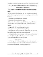
4-1 Systems to “Shut down” the Reactor
CRD and SLC shut off the nuclear reaction
CRD and SLC shut off the nuclear reaction
.
PCV
RPV
HPCF
Core
HPCF
Boron
solution
CRs
SLC Pumps
SLC storage
tank
1.ControlRod
Di (CRD)
2 Standby Liquid
S/P S/P
D
r
i
ve
(CRD)
2
.
Standby
Liquid
ControlSystem(SLC)
Copyright © 2011 Hitachi-GE Nuclear Energy, Ltd. All Rights Reserved.
5
PCV: Primary Containment Vessel
RPV: Reactor Pressure Vessel
S/P: Suppression Pool
Nl
PEii
tEl t i P U i it
N
uc
l
ear
P
ower
E
ng
i
neer
i
ng a
t
El
ec
t
r
i
c
P
ower
U
n
i
vers
it
y
4.Safety Systems of ABWR
4-1 Systems to “Shut down” a reactor
(CRD, SLC)
4-2 Systems to “Cool down” a reactor
(ECCS)
4-3 Structures or Systems to “Contain” a reactor
(PCV, FCS, R/B, SGTS, AC)
Copyright © 2011 Hitachi-GE Nuclear Energy, Ltd. All Rights Reserved.
6
Nl
PEii
tEl t i P U i it
N
uc
l
ear
P
ower
E
ng
i
neer
i
ng a
t
El
ec
t
r
i
c
P
ower
U
n
i
vers
it
y
4-2 Systems to “Cool down” the Reactor
Why does the core need to be
“
Cooled
Why does the core need to be Cooled
down” even after the “Shut down”?
RETRAN
code
Equation by
Todreas
Decay heat
compare to the
design thermal
fth
energy o
f
th
e core
Copyright © 2011 Hitachi-GE Nuclear Energy, Ltd. All Rights Reserved.
7
Because of the continuous Decay heat after the nuclear fission.
Nl
PEii
tEl t i P U i it
N
uc
l
ear
P
ower
E
ng
i
neer
i
ng a
t
El
ec
t
r
i
c
P
ower
U
n
i
vers
it
y
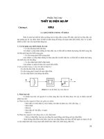
4-2 Systems to “Cool down” the Reactor
ECCS consists of 3 functions
ECCS consists of 3 functions
.
Pressure: approx.7MPa
inoperatingcondition
1:HighPressure
CoreInjection
PCV
RPV
Cool water
source
Core
To
Turbine
Cool water
Cool water
source
3:LowPressure
CoreInjection
2:
Depressurization
f
S/P S/P
o
f
RPV
Copyright © 2011 Hitachi-GE Nuclear Energy, Ltd. All Rights Reserved.
8
PCV: Primary Containment Vessel
RPV: Reactor Pressure Vessel
S/P: Suppression Pool
Nl
PEii
tEl t i P U i it
N
uc
l
ear
P
ower
E
ng
i
neer
i
ng a
t
El
ec
t
r
i
c
P
ower
U
n
i
vers
it
y
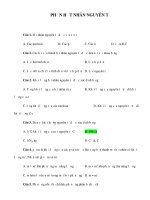
4-2 Systems to “Cool down” the Reactor
Redundancy and Independence of ECCS
Redundancy and Independence of ECCS
secure the margin of safety.
Redundancy
ABC
Redundancy
1.High pressure core
injection
HPCF HPCF RCIC
2.De
p
ressurization ADS
(
8 SRVs have the function.
)
3 functions of
p
of RPV
(
)
3.Low pressure core
injection
LPFL(RHR) LPFL(RHR) LPFL(RHR)
ECCS
injection
Independence
Emergency power source: D/G (Diesel
Generator)
D/G D/G
Copyright © 2011 Hitachi-GE Nuclear Energy, Ltd. All Rights Reserved.
HPCF: High Pressure Core Flooder
RCIC: Reactor Core Isolation Cooling
ADS: Automatic Depressurization System
LPFL: Low Pressure Flooder
RHR: Residual Heat Removal
9
Nl
PEii
tEl t i P U i it
N
uc
l
ear
P
ower
E
ng
i
neer
i
ng a
t
El
ec
t
r
i
c
P
ower
U
n
i
vers
it
y
4-2 Systems to “Cool down” the Reactor (ECCS)
High Pressure Core Flooder (HPCF)
High Pressure Core Flooder (HPCF)
HighPressure
HPCFinjectswaterintoRPVathigh
pressure to keep the Reactor water level
PCV
RPV
Cool water
pressure
to
keep
the
Reactor
water
level
.
CST
Core
Cool
water
Reactor
water level
HPCF
pump
(
motor driven
)
Hi
g
h
p
ressure
Firstwater
source
S/P S/P
()
Second
g p
injection
Copyright © 2011 Hitachi-GE Nuclear Energy, Ltd. All Rights Reserved.
Second
watersource
PCV: Primary Containment Vessel
RPV: Reactor Pressure Vessel
CST:Condensate Storage Tank
S/P: Suppression Pool
10
Nl
PEii
tEl t i P U i it
N
uc
l
ear
P
ower
E
ng
i
neer
i
ng a
t
El
ec
t
r
i
c
P
ower
U
n
i
vers
it
y
4-2 Systems to “Cool down” the Reactor (ECCS)
Reactor Core Isolation Cooling (RCIC)
Reactor Core Isolation Cooling (RCIC)
HighPressure
RCICinjectswaterint oRPVathigh
pressure with no electric supply
PCV
RPV
steam
MS line
pressure
with
no
electric
supply
.
CST
Core
Cool water
MS
line
RCIC
steam
Hi
g
h
p
ressure
Firstwater
Firstwater
source
(sameasHPCF)
S/P S/P
RCIC
turbine
RCIC pump
(turbine driven)
g p
injection
(sameasHPCF)
Second
Second
No electric
l
Copyright © 2011 Hitachi-GE Nuclear Energy, Ltd. All Rights Reserved.
11
PCV: Primary Containment Vessel
RPV: Reactor Pressure Vessel
CST:Condensate Storage Tank
S/P: Suppression Pool
Second
watersource
(sameasHPCF)
power
supp
l
y
Nl
PEii
tEl t i P U i it
N
uc
l
ear
P
ower
E
ng
i
neer
i
ng a
t
El
ec
t
r
i
c
P
ower
U
n
i
vers
it
y
4-2 Systems to “Cool down” the Reactor (ECCS)
Automatic Depressurization System (ADS)
Automatic Depressurization System (ADS)
HighPressure
Intheeventofanemergency,8
of SRVs open to make a path for
PCV
RPV
of
SRVs
open
to
make
a
path
for
MainSteamtotheS/Pto
protectRPVfromoverpressure.
L P
Core
MS line
To
Turbine
L
ow
P
ressure
steam
S/P S/P
condensate
Copyright © 2011 Hitachi-GE Nuclear Energy, Ltd. All Rights Reserved.
12
PCV: Primary Containment Vessel
RPV: Reactor Pressure Vessel
SRV:Safety Relief Valve
MS: Main Steam
S/P: Suppression Pool
Nl
PEii
tEl t i P U i it
N
uc
l
ear
P
ower
E
ng
i
neer
i
ng a
t
El
ec
t
r
i
c
P
ower
U
n
i
vers
it
y
4-2 Systems to “Cool down” the Reactor (ECCS)
Low Pressure Flooder System (LPFL)
Low Pressure Flooder System (LPFL)
LPFLinjectslargeamountofwater
into RPV at low pressure to keep the
PCV
RPV
L P
Water spray
into
RPV
at
low
pressure
to
keep
the
waterlevel.
Core
Cool water
L
ow
P
ressure
Low
p
ressure
Water spray
LPFL is one mode of RHR
S/P S/P
RHR
pump
RHR heat
p
injection
system.
Copyright © 2011 Hitachi-GE Nuclear Energy, Ltd. All Rights Reserved.
13
PCV: Primary Containment Vessel
RPV: Reactor Pressure Vessel
RHR:Residual Heat Removal
S/P: Suppression Pool
RHR
heat
exchanger
Nl
PEii
tEl t i P U i it
N
uc
l
ear
P
ower
E
ng
i
neer
i
ng a
t
El
ec
t
r
i
c
P
ower
U
n
i
vers
it
y
4-2 Systems to “Cool down” the Reactor (ECCS)
ECCS initiates automatically in the
ECCS initiates automatically in the
emergency situation.
PCV
RPV
1.Highpressure
PP
2.Lowwaterlevel
Detection of LOCA, the
LL
Core
MS line
Drywell
1. Drywell Pressure
“High” Signal
emergency situation
Wetwell Wetwell
2. Reactor Water Level
“Low”
S/P
S/P
Copyright © 2011 Hitachi-GE Nuclear Energy, Ltd. All Rights Reserved.
5-14
S/P
S/P
LOCA: Loss Of Coolant Accident
Nl
PEii
tEl t i P U i it
N
uc
l
ear
P
ower
E
ng
i
neer
i
ng a
t
El
ec
t
r
i
c
P
ower
U
n
i
vers
it
y
4.Safety Systems of ABWR
4-1 Systems to “Shut down” a reactor
(CRD, SLC)
4-2 Systems to “Cool down” a reactor
(ECCS)
4-3 Structures or Systems to “Contain” a reactor
(PCV, FCS, R/B, SGTS, AC)
Copyright © 2011 Hitachi-GE Nuclear Energy, Ltd. All Rights Reserved.
15
Nl
PEii
tEl t i P U i it
N
uc
l
ear
P
ower
E
ng
i
neer
i
ng a
t
El
ec
t
r
i
c
P
ower
U
n
i
vers
it
y
4-3 Constructions and systems to “Contain” a reactor
Containment systems not to discharge
R/B
Containment systems not to discharge
the fission products to outside.
PCV
Vessel Supporting
systems
R/B
Primary
Containment
PCV
・PCV spray
(cool down the inside
of PCV)
・FCS
(t t th h d
RPV
(t
rea
t th
e
h
y
d
rogen
and oxygen gas in PCV)
Secondary
Containment
R/B SGTS
(treat and discharge
either
p
rimar
y
or
py
secondary containment
air to outside via filter.)
Copyright © 2011 Hitachi-GE Nuclear Energy, Ltd. All Rights Reserved.
16
PCV: Primary Containment Vessel
RPV: Reactor Pressure Vessel
R/B:Reactor Building
FCS: Flammable gas Control System
SGTS: Standby Gas Treatment System
Nl
PEii
tEl t i P U i it
N
uc
l
ear
P
ower
E
ng
i
neer
i
ng a
t
El
ec
t
r
i
c
P
ower
U
n
i
vers
it
y
4-3 Constructions and systems to “Contain” a reactor
Primary Containment Vessel (PCV)
PCV shuts FP in the controlled
Design Philosophies
Primary Containment Vessel (PCV)
•Desi
g
n Pressure
PCV
shuts
FP
in
the
controlled
area.
PCV
g
inner pressure; 310kPa
outer pressure; 14kPa
•Allowance of Leak rate is
designed up to 0.4%/day.
•
Air is replaced by Nitrogen
RPV
•
Air
is
replaced
by
Nitrogen
gas in normal operation to
avoid detonation.
Copyright © 2011 Hitachi-GE Nuclear Energy, Ltd. All Rights Reserved.
FP; Fission Product
17
Nl
PEii
tEl t i P U i it
N
uc
l
ear
P
ower
E
ng
i
neer
i
ng a
t
El
ec
t
r
i
c
P
ower
U
n
i
vers
it
y
4-3 Constructions and systems to “Contain” a reactor
PCV Spray Cooling
PCV Spray Cooling
PCVSprayCoolingprevents
PCVfromexceedingitsdesign
PCV
RPV
Water
spray
pressureandtemperature.
Core
spray
Drywell
PCV s
p
ra
y
is one mode of
Wetwell Wetwell
Water
spray
S/P S/P
RHR
pump
RHR heat
py
RHR.
Copyright © 2011 Hitachi-GE Nuclear Energy, Ltd. All Rights Reserved.
5-18
PCV: Primary Containment Vessel
RPV: Reactor Pressure Vessel
RHR:Residual Heat Removal
S/P: Suppression Pool
RHR
heat
exchanger
Nl
PEii
tEl t i P U i it
N
uc
l
ear
P
ower
E
ng
i
neer
i
ng a
t
El
ec
t
r
i
c
P
ower
U
n
i
vers
it
y
4-3 Constructions and systems to “Contain” a reactor
Flammable Gas Control System (FCS)
Flammable Gas Control System (FCS)
FCScontrolsthemixtureof
Hydrogen and Oxygen gas in PCV
Hydrogengasby
l
i
PCV
RPV
Hydrogen
and
Oxygen
gas
in
PCV
,
whichcouldbeproducedduring
LOCA(LossOfCoolantAccident).
meta
l
‐waterreact
i
on
blowe
r
heate
r
Co
r
e
Hydrogen
and oxygen
MS line
SRV
MSIV
MSIV
Vacuum
Reaction
chamber
Co e
gas
water
MSIV
MSIV
Vacuum
breaker
cooler
Water
separator
water
Recombine
Hydrogen and
Hydrogenand
Oxygengasby
water radiolysis
breaker
Copyright © 2011 Hitachi-GE Nuclear Energy, Ltd. All Rights Reserved.
19
S/P S/P
Hydrogen
and
Oxygengas
water
radiolysis
Nl
PEii
tEl t i P U i it
N
uc
l
ear
P
ower
E
ng
i
neer
i
ng a
t
El
ec
t
r
i
c
P
ower
U
n
i
vers
it
y
4-3 Constructions and systems to “Contain” a reactor
Reactor Building (R/B)
Design Philosophies
Reactor Building (R/B)
R/B shuts FP in the controlled
area(the secondary barrier).
•Allowance of Leak rate is
designed up to 50%/day
*
.
•Pressure is maintained
negative by SGTS
negative
by
SGTS
.
*Allowance value in case of ABWR
Copyright © 2011 Hitachi-GE Nuclear Energy, Ltd. All Rights Reserved.
*Allowance
value
in
case
of
ABWR
SGTS; Standby Gas Treatment System
20
Nl
PEii
tEl t i P U i it
N
uc
l
ear
P
ower
E
ng
i
neer
i
ng a
t
El
ec
t
r
i
c
P
ower
U
n
i
vers
it
y
4-3 Constructions and systems to “Contain” a reactor
Standby Gas Treatment System (SGTS)
Design Philosophies
•
Radiological release to the environment
is prevented by maintaining R/B
Standby Gas Treatment System (SGTS)
Radiological
release
to
the
environment
is
prevented
by
maintaining
R/B
pressure negative(-63Pa).
• Radioactive substance in PCV are removed and captured in the filter
device.
device.
Reactor Area of Reactor Building(R/B)
Primary Containment Vessel(PCV)
Filt D i
•Exhaust fan
Number : 2 sets
Exhaust fan
Stack
Filt
er
D
ev
i
ce
Demoisturzer/
Capacity:
approx.2000m
3
/h
*
Exhaust
fan
Demoisturzer/
Heater
•Filter device
Number : 1 set
Filter Efficienc
y
:
Copyright © 2011 Hitachi-GE Nuclear Energy, Ltd. All Rights Reserved.
21
; Flow of atmosphere
y
over 99.99% for Iodine
*Capacity of ABWR
Nl
PEii
tEl t i P U i it
N
uc
l
ear
P
ower
E
ng
i
neer
i
ng a
t
El
ec
t
r
i
c
P
ower
U
n
i
vers
it
y
4-3 Constructions and systems to “Contain” a reactor
Atmospheric Control System (AC)
Atmospheric Control System (AC)
PCV
ACestablishtheinert
atmosphere of PCV with
Removes the
radioactive
RPV
atmosphere
of
PCV
with
Nitrogengas.
SGTS
(StandbyGas
Stack
Electricsupply
isrequired
substance in PCV.
Co
r
e
Nitrogen
gas
(inert gas)
TreatmentSystem)
inert
Co e
inert
Intherareseveraccident,
ACprotectPCVfrom
overpressurebyreleasing
fl
inert
Copyright © 2011 Hitachi-GE Nuclear Energy, Ltd. All Rights Reserved.
22
S/P S/P
gasviaSGTS,gas
f
i
l
tering
system.
Nl
PEii
tEl t i P U i it
N
uc
l
ear
P
ower
E
ng
i
neer
i
ng a
t
El
ec
t
r
i
c
P
ower
U
n
i
vers
it
y
Overview of ABWR Systems
ABWR
Power
Generation
St
Safety Systems Auxiliary
Systems
S
ys
t
ems
thi i d
thi i d
Copyright © 2011 Hitachi-GE Nuclear Energy, Ltd. All Rights Reserved.
23
thi
s per
i
o
d
thi
s per
i
o
d
Nl
PEii
tEl t i P U i it
N
uc
l
ear
P
ower
E
ng
i
neer
i
ng a
t
El
ec
t
r
i
c
P
ower
U
n
i
vers
it
y
5.Auxiliary Systems of ABWR
5-1 Systems to cleanup the reactor water
(CUW)
5-2 System to cool down the Spent Fuel Storage Pool
(FPC)
5-3 Ultimate Heat Sink
(RCW, RSW)
Copyright © 2011 Hitachi-GE Nuclear Energy, Ltd. All Rights Reserved.
24
Nl
PEii
tEl t i P U i it
N
uc
l
ear
P
ower
E
ng
i
neer
i
ng a
t
El
ec
t
r
i
c
P
ower
U
n
i
vers
it
y
5-1.Reactor Water Cleanup System (CUW)
PCV
Water
q
ualities
Feed Water Line
q
suchas
conductivity,
density of
RPV
T RHR
Re-generate type
Heat Exchanger
density
of
impuritiesare
controlledthrough
the filter devices
Filter
T
o
RHR
the
filter
devices
.
Device
Non-regenerate type
Heat Exchanger
Cleanupthe
Copyright © 2011 Hitachi-GE Nuclear Energy, Ltd. All Rights Reserved.
25
CUW Pump
reactorwater