Vibration control systems for civil engineering structure and infrastructure
Bạn đang xem bản rút gọn của tài liệu. Xem và tải ngay bản đầy đủ của tài liệu tại đây (1.48 MB, 55 trang )
5
Mass Inertia Effect based Vibration Control
Systems for Civil Engineering
Structure and Infrastructure
Chunwei Zhang and Jinping Ou
Harbin Institute of Technology, Harbin, Dalian University of Technology, Dalian,
P.R.China
1. Introduction
In 1972, J.T.P. Yao introduced the modern control theory into vibration control of civil
structures (Yao, 1972), which started the new era of research on structural active control in
civil engineering field. During the development of nearly 40 years, Active Mass
Driver/Damper (AMD) control, with the better control effect and cheaper control cost, has
taken the lead in various active control occasions, becoming the most extensively used and
researched control systems in lots of practical applications (Soong, 1990; Housner etal., 1997;
Spencer etal., 1997; Ou, 2003). Several important journals in civil engineering field, such as
ASCE Journal of Engineering Mechanics (issue 4th, in 2004), ASCE Journal of Structural
Engineering (issue 7th, in 2003), Earthquake Engineering and Structural Dynamics (issue
11th, in 2001 and issue 11th, in 1998), reviewed the-state-of-the-art in research and
engineering applications of semi-active control and active control, especially AMD control.
In addition, Spencer and Nagarajaiah (2003) systematically overviewed the applications of
active control in civil engineering. Up to date, more than 50 high-rising buildings, television
towers and about 15 large-scale bridge towers have been equipped with AMD control
systems for reducing wind-induced vibration or earthquake-induced vibration of the
structures.
Besides, there are quite a number of successful applications with passive Tuned Mass
Damper (TMD) control system, from wind induced vibration control of long-span bridge
towers and building structures, to chimneys and mast structures; from the first applications
of the collapsed World Trade Center towers and coetaneous John Hancock building etc.,
which were built in 1960s, to recently built highest structures in the world, e.g. Twin towers
in Kulua- Lumpur in Malaysia, 101 skyscraper in Taipei city and Guangzhou New TV tower
in China etc. It can be seen from these applications, the implementation of incorporating
Mass Driver/Damper based vibration control systems for protection of Civil Engineering
structures and infrastructures against wind and earthquake excitations, have already been
widely accepted by the field researchers as well as engineer societies.
2. EMD control systems
Zhang (2005) made a systematically comparison for different control schemes under the
background of the Benchmark control problem, and disclosed that the AMD control was the
Source: Vibration Control, Book edited by: Dr. Mickaël Lallart,
ISBN 978-953-307-117-6, pp. 380, September 2010, Sciyo, Croatia, downloaded from SCIYO.COM
www.intechopen.com
Vibration Control
106
best control scheme due to these merits, such as the best ratio of control effect over control
effort, simple and easy to be implemented etc. Moreover, through analysis of typical
important large-scale structures subjected to different excitations, the effectiveness and
feasibility of employing AMD control for civil structures has been successfully proven (Ou,
2003; Zhang, 2005), where wind and earthquake induced vibration control of high-rising
buildings and bridge towers, ice induced vibration control of offshore platforms, wind-
wave-current coupling excited control of deep sea platforms are all studied. Usually, an
AMD control system is composed of a mass piece, an actuator, stiffness component (coil
spring is commonly used), a damper, a stroke limiting device, a brake protector, sensors, a
data acquisition and processing system, computerized real-time control software and
hardware system (Dyke etal., 1994, 1996; Quast etal., 1995; Spencer etal., 1997). In addition, a
power supplying system is needed for operating all the electrical devices mentioned above.
In traditional AMD system, the mostly used actuators are hydraulic cylinders or electrical
servo motors, which may have the following disadvantages, such as large in system volume,
complicated in construction, time delay, slow to response, and limited mass stroke etc.
Aiming at this, several new special devices were put forward to replace the traditional
actuators (Haertling, 1994, 1997; Nerves, 1996; Scruggs, 2003). Learning from the motion
control principle of magnetic suspended vehicle, the electromagnetic mass damper
(subsequently called the “EMD”) control system, as an innovative active control system, was
proposed for structural vibration control (Zhang, 2005), which uses the driving technology
of linear electric machines, transforming the electric energy directly into mechanical energy
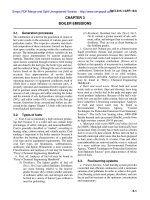
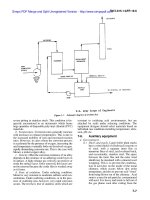
of EMD system, for example, the kinetic energy of EMD mass. Figure 1(a) shows the
conception sketch of hydraulic actuated AMD system and its implementation illustration in
a typical structural model, as shown in figure 1(b). By comparison, figure 2(a) and 2(b)
shows the corresponding sketch and implementation sketch of the EMD control system.
Fig. 1. Sketch of structure with hydraylic actuated AMD control System
www.intechopen.com
Mass Inertia Effect based Vibration Control Systems for Civil Engineering Structure and Infrastructure
107
Fig. 2. Sketch of structure with Electromagnetic Mass Damper (EMD) contol system
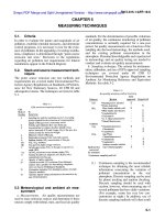
2.1 Miniature EMD control system
The miniature experimental EMD control system is composed of a mass piece (direct current
excitation coils encapsulated in high-strength engineering plastics, with mounting holes on
its surface), a permanent magnet rod made of high energy rare earth material, linear sliding
bearings and the system chassis. In addition, in order to form a closed-loop EMD system, an
optical scale and an accelerometer are integrated into the EMD system to measure the stroke
and absolute acceleration of the mass, respectively. Photo of the whole integrated system is
shown in figure 3.
EMD mass
Magnet rod
Optical scale
Linear bearings
Accelerometer
System chassis
Reader head
Fig. 3. Integrated photo of the EMD actuator
The excitation coil in the sealed mass package is 87mm long, made by Copley Controls Inc.,
and the whole mass piece weighs 186 grams. The permanent magnet rod is 332mm long
with the diameter of 11mm. The main electrical specifications of this EMD system are: peak
force constant is 5.74N/A, root mean square (RMS) force constant is 8.12N/A, back electro-
www.intechopen.com
Vibration Control
108
motive force (EMF) constant is 6.63
Vs/m
⋅
, the coil resistance at 25°C is 5.35
Ω
, and the coil
inductance is 1.73mH. The mass stroke of EMD system is measured using a Renishaw
optical scale, which is pasted onto the system chassis as shown in the photo above, while the
reading head is fixed on the side wall of EMD mass. The reading head model is RGH24 with
the resolution of 2-micro-meter, and the scale is 220mm long. In addition, one tiny
accelerometer (type DH201-050) is installed on the prolonging side-wall of the EMD mass
with the measuring range of ±50g. This accelerometer is very compact indeed, with a weight
of only two grams and a volume of 10mm×10mm×5mm, and it can be conveniently attached
to any part of the mass piece without influencing the operation of the whole system.
2.1.1 System mathematical models
From the aspect of circuit calculation, the armature of EMD system consists of three parts:
motor coil which is capable of outputting mechanical force or energy, coil inductance and
coil resistance. According to the Kirchhoff's first principle, the relationship of the circuit
voltage and current can be written as
()
() () ()
mm m
di t
LRittVt
dt
ε
++=
(1)
Where
m
L is the coil inductance,
m
R is the coil resistance, ()
m
Vt is the input voltage, ()t
ε
is
the inducted back EMF constant, ()it is the current intensity in the coil.
Defining the following two electric indices of linear motors,
EMD
f
F
K
I
=
standing for force
constant which means electromagnetic force generated by unit current input, and
m
K
v
ε
=
standing for the back EMF constant which means back EMF generated by unit velocity, then
the following relationships are reached,
EMD
() /
f
it F K
=
; ()
m
tKv
ε
=
(2)
Substituting equation (2) into equation (1) gives
() 1
() () ()
m
mmm
ff
R
dF t
LFtKvtVt
dt K K
++=
(3)
After proper transformation, equation (3) can be rewritten as,
()
() () ()
ffm
m
ma
mmm
KKK
L
dF t
Ft V t x t
RRRdt
=− −
$
(4)
Where
a
x
$
is the relative velocity of EMD mass, and (t)F is the controllable electromagnetic
force.
2.1.2 System dynamic tests
During dynamical tests, the EMD system is fixed on the shaking table, and the system coil is
powered with the ASP-055-18 servo amplifier, with a DC current output of 0~10A and
voltage of 0~55V. The power supply is the HB17600SL series regulator module. A series of
www.intechopen.com
Mass Inertia Effect based Vibration Control Systems for Civil Engineering Structure and Infrastructure
109
sine position based tests under Position-velocity control of large mass strokes and low
frequencies are conducted.
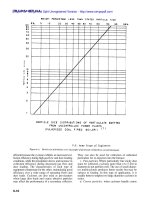
For example, figure 4 shows the hysteresis loops of control force versus velocity and circuit
current, respectively. From the force-current relationship, fine linear relationship again
indicates the EMD system to be a linear actuator under low operating frequencies, with high
ability in dissipating energy at the same time.
Fig. 4. Force hysteresis loops of EMD system
2.1.3 Experimental implementation of structural model
The test structural model employed in this part is a two-story shearing type structure, called
the Bench-scale structure, manufactured by Quanser Inc., which has been designed to study
critical aspects of structural control implementations and widely used in education or
research of civil engineering and earthquake engineering throughout the world (Battaini,
2000; Quanser, 2002). The column of the test structure is made of thin steel plate, 2mm thick,
and the floors are made of plastic, 13mm thick, and the inter-storey height of the structure is
490mm. Shaker-II table, made by Quanser Inc., is employed here for generating earthquake
excitations as well as other excitations to be exerted onto the test structure. Through sine
sweep test, the natural frequencies of the structure are found to be 1.27Hz and 4.625Hz
corresponding to the first two dominant vibration modes respectively, where the mass of
the EMD system is fixed on the top floor, named as uncontrolled case. The photo of the
whole experimental system and its calculation sketch are shown in figure 5.
In the current experimental setup, two accelerometers are installed under each floor and
another accelerometer ia installed on the shaking table surface to measure structural
response and input excitation respectively. The acceleration transducers are the type of
Kistler K-Beam 8034A with the measuring range being ±2.0g and the sensitivity gain being
1024mV/g. Two laser displacement sensors, type of Keyence LK-2501/2503, are employed
to measure the absolute displacement of each floor of the structure, which both work under
the long distance mode, and the measuring range is ±250mm with the gain being
200mV/cm. Here the displacement measurement is used only for verification purpose,
while not for feedback.
In this section, shaking table tests of structural seismic response control employing the EMD
system were conducted, where three benchmark earthquake waves were used as input to
examine the control effectiveness of such an innovative active control system, and typical
results under Kobe earthquake wave (NS, January 17, 1995) input will be shown in the
www.intechopen.com
Vibration Control
110
Digital
controlle
r
Servo-amplifier
1
k
1
c
2
k
2
c
1
m
2
m
g
x
$$
c
V
m
V
Shaking
table
Accelerometer
1
x
$$
2
x
$$
a
x
a
m
a
c
Accelerometer
Fig. 5. Photo and calculation sketch of whole system
0 5 10 15 20 25 30
-10
-5
0
5
10
Time (s)
Acceleration (m/s
2
)
Uncontrolled
Zeroed
EMD control
(a) Absolute acceleration of the first floor
0 5 10 15 20 25 30
-15
-10
-5
0
5
10
Time (s)
Acceleration (m/s
2
)
Uncontrolled
Zeroed
EMD control
(b) Absolute acceleration of the top floor
Fig. 6. Experimental structural acceleration under Kobe wave excitation
www.intechopen.com
Mass Inertia Effect based Vibration Control Systems for Civil Engineering Structure and Infrastructure
111
0 5 10 15 20 25 30
-100
-50
0
50
100
Time (s)
Di
sp
l
acemen
t
(
mm
)
Uncontrolled
Zeroed
EMD control
(a) Absolute displacement of the first floor
0 5 10 15 20 25 30
-100
-50
0
50
100
Time (s)
Di
sp
l
acemen
t
(
mm
)
Uncontrolled
Zeroed
EMD control
(b) Inter-drift of the top floor
Fig. 7. Experimental structural displacement under Kobe wave excitation
0 10 20 30
-2
-1
0
1
2
Time (s)
Control voltage (V)
0 10 20 3
0
-100
-50
0
50
100
Time (s)
Mass stroke (mm)
Fig. 8. Time history of control voltage and mass stroke of EMD system under Kobe wave
excitation
following part. During the experiment, laser transducers are used to measure the absolute
displacements of each floor of the test structure, and the inter-storey deformation can be
calculated through subtraction of displacements of adjacent floors.
Figure 6 and figure 7 show the comparison of the structural absolute acceleration and floor
displacement and inter-drift under three cases, Uncontrolled, Zeroed and EMD active
control respectively. From the results, the EMD control is shown to be the most effective in
suppressing structural vibrations. In addition, time histories of control voltage and mass
stroke of the EMD system are also shown in figure 8.
www.intechopen.com
Vibration Control
112
In the above, theoretical modeling, dynamical testing, shaking table tests have been
systematically carried out for the miniature EMD control to investigate its feasibility for
using in structural vibration control. All the results show it to be a promising active control
system for civil engineering.
2.2 Benchmark scale EMD control system
The existing linear motor products are already getting so close to rotatory motors in
velocitty regulation area, and the products are mostly low power motors to drive the AMD
mass (Zong etal.,2002). Requested performances of AMD system used for vibration control
of civil engineering structures are high power, heavy load and high response ability to
frequency, however control accuracy is not necessarily requested. Sometimes the servo
motor power may exceed hundreds or thousands of Kilowatts. One of the possible means to
solve the problems is to use simple tri-phase asynchronous linear motors in the design of
full scale AMD control system.
An approach of setting up the high power linear electrical motor servo system is studied in
this part. To build the high power position servo system, normal frequency transducer is
used to drive an asynchronous linear motor. Because the mathematical model of
asynchronous motor is not easy to set up, a new controller design method based on the step
response of the closed-loop system is introduced, and series of numerical simulations and
experimental verifications were carried out. Experimental results showed that good control
performance can be achieved using the designed controller for the physical system.
2.2.1 Principles of position control for asynchronous linear motor
Constitution of traditional rotatory position servo systems is shown in figure 9. In the
traditional structure, rotatory machines and ball bearing screw are used, and the mass load
is driven to perform linear motion. Due to the avoidless clearance between screw and load,
transmission accuracy gets declined and the servo rigidity is affected. Linear motors are
taken in to drive the load in the linear electric motor position servo system shown in figure
10. Without transmission components and movement transform, higher transmission
accuracy and servo rigidity are achieved from asynchronous motors. At the same time,
higher accuracy and dependability are achieved from whole position closed-loop system
with raster ruler instead of rotatory encoder than half closed-loop system.
Fig. 9. Sketch of Rotary Servo System for Position Control
www.intechopen.com
Mass Inertia Effect based Vibration Control Systems for Civil Engineering Structure and Infrastructure
113
Fig. 10. Sketch of Linear Servo System for Position Control
Applications of linear motors focus on low power situations such as disk reader, printer,
and numerical machine tools, so high power linear motion servo driver equipments can’t be
purchased. All the correlative hardware equipments have to be designed independently (Ye,
2003). This part takes vector alternating frequency transducer driver and asynchronous
linear motor instead of position servo system, and makes use of computer servo control card
to perform the controller’s function, then builds the integrated servo system with
asynchronous linear motor. The frame of the whole system is shown in figure 11.
From figure 11, functions of the components are shown: Control computer plays the role of
servo controller. The position command signal is generated in MatLab/Simulink. Position
error is calculated out from position command and position feedback from raster ruler, then
velocity command signal is calculated, at last velocity voltage is produced from real-time
control software WinCon and servo control card to frequency transducer. The linear motor
is driven by the frequency transducer to run at the assigned speed according to the velocity
command. The load is driven by the linear motor to perform linear motion displacement
following the position command.
Fig. 11. Position Control of Asynchronous Linear Motor
Based on the structure shown in figure 11, equipments are chosen according to the power
requirement. A tri-phase asynchronous linear motor with the power 4.5 kW, synchronous
speed 4.5 m/s (50 Hz) is ordered, and a speed slip of 0.05 (5%) is estimated from
experiments. The linear motor driver is Delta VFD-V model, high performance vector tri-
phase alternating frequency transducer, with driving power of 5.5 kW. Position feedback
tache is the most important component of the whole system, so a raster ruler produced by
Renishaw Co. is chosen. Model of the ruler reader is RGS20, and minimal resolving power
of the raster is 20 um. MultiQ-3 servo control card produced by Quanser Co. is setup in the
control computer, with software of WinCon3.2 and Matlab 6.0. Structure of the whole
www.intechopen.com
Vibration Control
114
asynchronous linear electric motor is shown in figure 12. Figure 13 shows the picture of the
experiment equipment and the software runtime is shown in figure 14.
Fig. 12. Structure of the Position Control System
Fig. 13. Picture of the Control System
Fig. 14. Picture of the running WinCon
2.2.2 System model and position controller design
Traditional control method and controller design is commonly based on mathematics model of
the object under control, and the controller is calculated according to required performance.
Generally, mathematics model of the system is obtained by the method of analyze or system
www.intechopen.com
Mass Inertia Effect based Vibration Control Systems for Civil Engineering Structure and Infrastructure
115
identify, estimating model from the input and output experimental data. For the mathematic
expression of asynchronous linear motor is so complex and parameters the manufacturer
offered is not enough to build the model from analyze. At the same time, experiment situation
of linear motor is limited by dimensions of the platform, so experiments can’t be implemented
to get enough data system identify required, which makes design of the controller much more
difficult. In the engineering problem design process, simplification of the mathematics model
usually makes the controller difficult to actualize or get awful performance. So a simple and
facile approach that fits the engineering application is necessary.
This part analyzes and summarizes most of the design methods and tries a new design
method. Reference to the design method of Extraction of Features of Object’s Response,
briefly EFOR, an approach to design the Lag-Lead compensator based on the experimental
step response of the closed-loop system is implemented and good performances is achieved.
Basic idea of quondam EFOR method is described as below: closed-loop simulation is
carried out to a series of “Normal Object”, to get the step response, and then some main
time characteristic parameters are read out, and the controller is designed according to the
parameters. The “Normal Object” is provided with some special characters: transfer
function is strict proper rational point expression or proper rational point expression;
minimum phase; at most one layer integral calculus; magnitude-frequency character is
monotonous reduced function to the frequency (Wu etal., 2003).
Experiments showed that the asynchronous linear motor system couldn’t satisfy all the
requirement of the “Normal Object”, especially the magnitude-frequency character is not
monotonous reduced function to the frequency. But the step response of closed-loop system
is similar to the attenuation oscillatory of the second-order system, so the EFOR method
could be attempted to design the controller. So reference to the EFOR design method, a new
method of Lag-Lead compensator design based on the experimental test is tried to
accomplish the controller design. Detailed design process is shown below:
a.
Step response experiment is carried out, especially the curve of high oscillatory with
similar amplitudes, and attenuation oscillatory periods dT is obtained, and then the
frequency of system attenuation oscillatory 2/ddT
ω
π
=
is calculated, at last the critical
attenuation oscillatory
p
ω
is estimated; The experimental method is especially fit for some
systems which only perform movement within limited displacement such as linear
electric motors. These systems have only limit experiment situation and can’t perform
long time experiments. The curve of high oscillatory with similar amplitudes when the
proportion control coefficient is
Kp=15 from the experiments is shown in figure 15.
Parameters below are obtained:
2.926 1.702 1.224dTs
=
−= (5)
2 / 5.133 /pd dTrads
ω
ωπ
≈
==
(6)
The Lag-Lead compensator is designed according to equivalence oscillatory frequency.
Structure of the lead compensator is shown below:
2
1
/
() ( 1)
1
m
m
h
m
m
s
s
Ks
s
s
ω
ωλ
λ
λλ
λω
λ
ω
+
+
=
=>
+
+
(7)
Design of the lead compensator is mainly the chosen of parameters
λ
and
m
ω
.
www.intechopen.com
Vibration Control
116
Fig. 15. Curve of Critical Oscillating System from Experiments
Parameter
λ
is named compensator strength. Larger
λ
produces plus phase excursion and
better performance; too larger
λ
produces phase excursion increased not evidently, but
makes the higher frequency gain so large that the high frequency noise is enlarged. So the
λ
should be selected based on the exceed quantity
λ
, usually from the empirical formula
1.2 4 ( 0.6)
{
3.6 ( 0.6)
σσ
λ
σ
+≤
=
>
(8)
So the compensator strength for the current system is 3.6
λ
=
.
The compensator mid-frequency m
ω
should be a little higher than
p
ω
. For the second-
order system, usually from the empirical formula
m
p
ω
λω
= , so
3.6 5.133
9.740 /
mp
rad s
ωλω
==×
=
(9)
Thereby the lead compensator is achieved:
1
0.37 1
/
()
0.0285 1
1
m
h
m
s
s
Ks
s
s
ωλ
λω
+
+
==
+
+
(10)
b. The main purpose of the lag compensator is to reduce the stable error, but phase will
usually be reduced, too, so the lag compensator parameters should be determined by
the steady error after the lead compensator added. For the system that the error fits the
requirement, a lag compensator is not necessary. Usually structure of the lag
compensator is like this:
1
1
1
()
s
Ks
s
ω
ρ
ω
+
=
+
(11)
www.intechopen.com
Mass Inertia Effect based Vibration Control Systems for Civil Engineering Structure and Infrastructure
117
In the expression, the compensator strength is 0 1
ρ
<
< . 1
ω
is the seamed frequency of
the lag compensator, so it must be lower than magnitude crossing frequency c
ω
and not
close to
c
ω
, to reduce the effect to mid-frequency performance. Usually
1 (0.1 ~ 0.2) c
ω
ω
≈ , 1 / n
ρ
=
, so that the steady error could be reduced to 1/n嫋
Accordingly, the position controller is designed for the system. The perfect proportion
control coefficient is Kp=8. Figure 16 shows the controller structure.
Fig. 16. Structure of Lag-Lead Controller
2.2.3 Simulation and experimental results
The lag-lead compensator based on the step response is
(
)
(
)
( ) 0.37 1 / 0.0285 1hKs s s
=
++,
and the perfect proportion control coefficient is Kp=8. With the method of getting controller
coefficient from test-run, the best perfect coefficient for only proportion controller is Kp=8,
and the best perfect coefficient for proportion differential controller is Kp=8, Kd=0.4. The
coefficients are applied in the simulations and the experiments below.
By analyzing parameters of the lag-lead compensator and some conclusion from system
identification, a simplification model was estimated to test the performance of the
controllers. Simulations using different controllers such as lag-lead compensator, proportion
controller, or proportion differential controller were carried out with the help of Matlab
software. Simulation result with different controllers is shown in figure 17.
Fig. 17. Results of the Simulations using three different controllers
The figure shows that the lead compensator and the proportion differential controller make
great improvement to the object under control. Compared with simple proportion
controller, the response speed and the position control error are reduced a lot.
www.intechopen.com
Vibration Control
118
Some experiments were performed on the mechanic equipments. Figure 18 shows the
performance of the lead compensator while adjusting the proportion coefficient near Kp=8.
The performance of following ability test under the lead compensator is shown in figure 19.
Obvious following effect to the sine position command with magnitude 50mm and
frequency 1Hz is obtained.
Fig. 18. Experiment Results using different Kp
Fig. 19. Experiments Curve of Sine Signal Response
Based on the experiments, the performances of the three different controllers are shown in
figure 20.
www.intechopen.com
Mass Inertia Effect based Vibration Control Systems for Civil Engineering Structure and Infrastructure
119
Fig. 20. Comparison of the Experiment results using three different controllers
The following function parameters based on step response are obtained from figure 20.
System Function
Value
ising
Time/s
ransit
Time/s
Surpass
Amounts
teady
Error
Oscillation
Number
LagLeadcontroller .37 .96 11.5% % 2
KD Controller .62 .97 6% % 1
Kp Controller .73 .9 64% % 3
Table 1. Comparison of Function Values from Experiments using three different controllers
The functional parameters shows that the controller designed by the method based on the
experimental step response of the closed-loop system improves the system performance a
lot, even much better than the proportion differential controller, while the design process is
far simple than the design of PD controller.
2.3 Energy harvest EHMD control system
In the following figure 21, the main parts of the innovative EHMD system and their
relations were illustrated, respectively. The EHMD system can be divided into the following
parts: TMD subsystem with energy dissipating and recycling functions, power module
which can preserve and release electrical energy, EMD subsystem which is directly driven
by electro-magnetic force. To be specific, TMD damper is replaced by coils embedded fly-
wheels combined with high-power batteries, EMD active force is realized using soft
magnetic material actuator and high-power capacitor; besides, the standard DSP module is
incorporated to make up a real-time control system. The fly-wheels is composed of wheel
body, reducer or accelerator using gear boxes, energy generating and dissipating coils, high
power storage battery and capacitor, electronic and electrical regulator, as well as
mechanical couplings and attachments etc. Considering the fly-wheel battery is relatively a
matured technique, here the EHMD should be focused on solving its control strategies to
realize a reasonable energy preserving-releasing process for structural active control.
www.intechopen.com
Vibration Control
120
N
S
N
S
(Note: 1-digital controller, 2-fly-wheel(s), 3-spring element, 4-mechanical couplings, 5-
system mass (embedded coils), 6-energy-storing battery, 7-excitation coils, 8-bearings and
system rails, 9-permanent magnets)
Fig. 21. Structural integration photos of EHMD system
In the following figure 22, analysis and design procedure of the EHMD system is proposed.
First, aiming at the requirement of the specific structure to be controlled, optimal mass ratio,
stiffness and damping coefficients, maximum mass stroke and peak control force were
calculated, which were set as the hardware standard parameters of the moderate scale
EHMD system. Second, applying relevant research results, such as linear motor technique in
magneto suspension trains and energy accumulation technologies in fly-wheel batteries etc,
key parts of energy recycling, preserving and utilizing for driving EHMD system would be
developed. At last, integrating DSP based data acquisition, processing and real-time control
modules, the whole experimental EHMD system are fabricated and integrated.
When the structure vibrates, the mass moves driving the couplings rotating which
transforms linear motion into rotation, and the embedded coil cut the magnetic field and
generates induction currents and stored in the batteries which will be utilized at a
E2-HMD
system mass
Couplin
gs
Gear
boxes
Flying -
wheels
Electronic
re
g
ulator
EMD
actuator
Storage
battery
DSP real-time control
modules
Structure
sensors
Fig. 22. Structural construction sketch of EHMD system
www.intechopen.com
Mass Inertia Effect based Vibration Control Systems for Civil Engineering Structure and Infrastructure
121
reasonable occasion. If reducer or accelerator is incorporated into the system, then the
efficiency of generating electrical power can be greatly improved, through calculations the
optimal gear ratio and damping coefficient can be achieved.
In the following, feasibility of utilizing such kind of EHMD system for suppressing
structural vibrations will be considered. Basically, the main problems will be focused on the
electrical loops of the system, because the other two major parts will be benefited from AMD
and TMD control techniques. Currently, a high-power capacitor can be stored with energy
of up to 3MJ, where its energy density will be 1.35kJ / kg and about 1.5kJ / dm
3
, thus the
mass will be about 2m
3
and the weight will be 2tons or so, which can power the EMD
actuator in continuous working mode for more than 200 seconds. From the data, the EHMD
for protection of structural seismic response is absolutely feasible.
3. DDVC based AMD control system
This DDVC based active mass driver control system is proposed for low frequency vibration
and motion control, e.g. wave induced motion control of offshore platform structures.
DDVC (Direct Drive Volume Control) technology comes from the hydraulic industry, which
utilizes integrated pump and motor to replace servo valve from traditional hydro cylinders,
and to realize such functions as pressure control, speed control and changing working
directions etc. DDVC control is also called as valve-less control, which uses servo AC motors
driving fixed displacement pumps. DDVC is operated based on regulating rotary speed of
pumps rather than changing its flow, and to control actuating speed of actuators. DDVC has
been widely researched by institutions from Japan, USA, German, Sweden and China. The
most common applications are used in such industries as high-precision forging machinery,
ship helms, heavy load casting machineries, printing machines, 6-DOF platforms and rotary
tables, 2500 ton inner high pressure shaping machine, operating switch for floodgates etc.
Besides, some applications have been proposed for aerospace engineering (also called EHA,
Electrical Hydro Actuator) recently because the most attracting advantages of compact
volumes, high energy saving efficiencies etc.
Figure 23 shows the photo of one typical DDVC system fabricated by 1
st
Japan Electric
Corporation. DDVC-AMD is an innovative replacement of actuator from traditional hydro
cylindrical AMD control system, and figure 24 shows the working principles of such DDVC
actuated AMD control system.
Fig. 23. Photo of DDVC driver
www.intechopen.com
Vibration Control
122
Fig. 24. Principle chart of DDVC-AMD system
Fig. 25. Simulation block diagram for DDVC-AMD control system
The following section established the formulations for DDVC based AMD control system.
Motor control loop, hydraulic power plant and actuation part were studied and numerically
validated. As shown in figure 25, Simulink simulation block diagram was used to perform
numerical simulations and comparisons on the force-displacement hysteresis loops are
given in figure 26. Furthermore, structural seismic response control using DDVC-AMD are
numerically studied. Figures 27 to 28 show some preliminary results under Kobe and
Hachinohe earthquake excitations, which indicates the feasibility and effectiveness of such
system for structural vibration mitigation.
www.intechopen.com
Mass Inertia Effect based Vibration Control Systems for Civil Engineering Structure and Infrastructure
123
Fig. 26. Hysteresis loops of DDVC-AMD under different loading amplitudes
a) Displacement of first floor b) Acceleration of first floor
Fig. 27. Kobe earthquake excitation
a) Displacement of first floor b) Acceleration of first floor
Fig. 28. Hachinohe earthquake excitation
www.intechopen.com
Vibration Control
124
4. Structural swinging motion and vibration control
Vessel-mounted cranes of heavy lifting and pipeline paving ships are used to construct large
scale offshore structures, such as steel jacket platforms and oil-gas transporting pipeline
systems etc. Owing to the complicated conditions of ocean environment, the wave-induced
ship motion, sometimes wind-wave-current coupling excitations of the crane ship produces
large pendulation of hook structure, which causes normal operations of the ship to be
suspended and results in economic losses. For example, when the wind speed exceeds 6
degree, the probability of suspended operations will be about 50%, which greatly affects the
construction progress.
Based on a large amount of observations on the hook vibration, the pendulation can be
divided into two types: in-plain motion and rotary motion with respect to certain axis
(namely gyrus motion). After thorough numerical simulations and experimental
verifications, the control solution corresponding to each type of the motion is found to be
absolutely different.
In the followings, the modeling of two motion modes and the methods of suppressing
different types of pendulation of hook structure will be discussed respectively, and
eventually be experimentally verified on a scale model structure.
4.1 Theoretical modeling
The calculation sketch of the crane ship can be simplified as a SDOF system, which is
represented using a basket model as shown in figure 29, and a passive TMD (Tuned Mass
Damper) control system is attached onto the structure. Based on the measurement of the
motion of the suspended hook structure, the pendulation could be classified into two modes
owing to different relation between suspension points and motion direction as shown in
figure 29, where SP stands for “suspension points”.
After thorough theoretical analysis and numerical simulations, the two types of motion is
found to be absolute different, and the Lagrange’s equation is introduced to model each
motion mode respectively. As shown in figure 30, to quantity compare the differences, the
hook is simplified as a bar with two masses on each end, besides the TMD system is
simplified as a spring-mass second system. Using x stands for mass strokes of TMD system,
Fig. 29. Suspension points and motion directions
www.intechopen.com
Mass Inertia Effect based Vibration Control Systems for Civil Engineering Structure and Infrastructure
125
(a) In-plain motion
(b) Rotary motion
Fig. 30. Typical motion modes
l stands for the length of suspension cable, θ stands for pendulation angle with respect to
vertical direction, m stands for one half of the mass of hook structure, m
a
stands for mass of
TMD control system.
The whole system shown in figure 30(a) has the following kinetic energy and potential
energy expressions:
222
11
cos
22
aaa
Tmlmlmxmlx
θ
θθθ
=+ + +
$$ $
$$
(12)
()()
2
1
21cos 1cos
2
a
Vmgl mgl kx
θθ
=−+−+
(13)
Using Lagrange’s formulation, LTV
=
− , 0
dL L
dt x x
∂∂
⎛⎞
−
=
⎜⎟
∂∂
⎝⎠
$
and
0
dL L
dt
θ
θ
∂∂
⎛⎞
−
=
⎜⎟
∂
∂
⎝⎠
$
, we have
www.intechopen.com
Vibration Control
126
2
sin cos
a
k
xxl l
m
θ
θθ θ
+= −
$$$
$$
(14)
22
2cos2sinsin0
aa a
ml m l m lx mgl m gl
θθ θ θ θ
+
+++=
$$ $$
$$
(15)
Equation (14) gives the solution of TMD mass strokes relative to the main structure, and
equation (15) is the standard formula of simple pendulum structure.
For comparison, the kinetic energy and potential energy of the system shown in figure 30(b)
has the following expressions:
()
22 2 2 2 2
1
11
22
aa a
Tml mx ml x mxl
θ
θθ
=++ ++
$$$
$
(16)
()( )
2
1
2 1 cos cos sin
2
a
Vmgl mgll x kx
θθθ
=−+−++
(17)
Where l
1
is the distance between suspension point and concentrated mass of the suspended
structure. Similarly, using Lagrange’s formulation, the equation of motion can be achieved
as
2
sin
a
k
xxxlg
m
θ
θθ
+=−−
$$$
$$
(18)
(
)
222
1
22
2sin sin cos0
aaa
aa
ml m l x m xx m lx
mgl m gl m gx
θθθ
θθ θ
+
++ ++
++ =
$$ $$ $
$$$
(19)
4.2 Numerical simulation
Assuming the system parameters are m=5kg, ma=0.5kg and l=10m, imposing an initial
kinetic energy on the suspended structure shown in figure 30(a) and the dynamical response
of the system is listed in the figure 31.
Here assuming there is no damping existed in the TMD system, thus the vibration of the
system will not be suppressed, and energy exchanges between the TMD control system and
the main structure, as shown in figure 31(a) and 31(b). In figure 31, the unified force is
defined as the sum of the two items in the right hand side of equation (14). From the
definition we can see that such kind of unified force is independent of mass strokes x, which
was also verified by the simulation results shown above. From both the figures and the
equations, we can see that the unified force of the TMD system is proportional to the
vibration amplitude of the structure, which is equals to the control force which is imposed
onto the main structure. Thus the TMD system behaves like a closed-loop feedback control
system of the structure (Zhang etal., 2006).
On the other hand, equation (18) gives the equation of TMD mass in the second suspension
case, where the last two items are the ideal motion equation of the simple pendulum system.
The control force of TMD system is shown to be dependent on the product of x times
angular velocity. After a lot of simulations, the mass stroke is shown to be very small, which
can not provides sufficient control force to suppress the structural vibrations. Moreover, the
www.intechopen.com
Mass Inertia Effect based Vibration Control Systems for Civil Engineering Structure and Infrastructure
127
control effectiveness is also affected by the initial phase lags between TMD mass and the
hook displacement. As a result, traditional TMD system will lose its effects during the rotary
motion mode.
Time (sec)
Unified force
Time (sec)
Angle (rad)
(a) Time history of control force (b) Time history of angular displacement
Uni
f
ied force
Angle (rad)
Unified force
Angular velocity (rad/s)
(c) Hysteresis loop of force-displacement (d) Hysteresis loop of force-velocity
Fig. 31. Numerical simulation responses of in-plain vibration mode
4.3 Solutions for rotary and swinging motion control
For the rotary motion mode, which is exactly similar to the gyrus motion or swing vibration
of a simple pendulum, the gravity acceleration plays both as disturbance force and restoring
force at the same time, thus the ability of the traditional in-plain control device is of no effect
any longer, and innovative mechanism or special device, which can exert control torques to
suppress such gyrus motion should be developed.
Taking a simple pendulum system for example, the suspended structure and the gyrus
motion control system is shown in figure 32, where m
0
is the mass of hook structure, l
0
is the
length of suspension cable, r is the radius of fly-wheel, for simplification, m is the
representative value of half mass of the fly-wheel, θ and φ are angle of wheel rotation and
vertical direction respectively.
Kinetic and potential energy of the simple pendulum and rotary control system shown in
figure 32 are given below, where k
t
is the stiffness coefficient of torsion spring.
22 22
00
1
()
2
aa
Tmml mr
ϕ
θ
=+ +
$
$
(20)
2
00
1
(2)(1cos) ()
2
at
Vm mgl k
ϕ
θϕ
=+ − + −
(21)
www.intechopen.com
Vibration Control
128
Fig. 32. Computational sketch of rotary motion
Fig. 33. Numerical simulation responses of in-plain vibration mode
Using Lagrange’s principal, the system equations of motion can be achieved as
(
)
(
)
(
)
2
000 0
22sin0
aat
mml mmgl k
φφφθ
+
++ − −=
$$
(22)
(
)
2
20
at
mr k
θθϕ
+
−=
$$
(23)
In order to control the rotary motion, the control system must be able to rotate relative to the
pendulation of the hook structure. The innovative tuned torsion inertia damper system is
composed of torsion spring element, fly-wheel, gear boxes and necessary connecting
accessories is developed and its main structure is shown in figure 33. If the reducer gear box
is introduced, then the volume of the whole rotary control system can be greatly reduced,
and the rotation inertia of the control system can be increased by i
2
times, where i is the gear
ratio. The intrinsic characteristic of such an innovative rotary control system is to use high
rotation speed to make up for the smaller physical rotation inertia indeed. After
incorporating gear box device, equations (22) and (23) can be rewritten as
ψ
θ
m
0
m
a
m
a
l
0
r
suspension
point
fly-wheel
Gear Box body
(GB)
torsion
spring
connecting frames
output shaft
of GB
input shaft
of GB
connecting
holes
www.intechopen.com
Mass Inertia Effect based Vibration Control Systems for Civil Engineering Structure and Infrastructure
129
0120
2
0120
1
[( ) sin ( )]
()
t
mmmgl k
mmml
φ
ϕθϕ
=−+++−
++
$$
(24)
22 2
11 22
1
[( )]
()
t
k
mr i mr
θ
θϕ
=−−
+
$$
(25)
Where m
1
is mass of the input shaft (low speed end) of reducer GB box and r
1
is the rotation
inertia radius of m
1
, m
2
is the mass of output shaft (high speed end) of reducer GB box and r
1
is the corresponding rotation inertia radius.
4.4 Innovative TRID control system
TRID system, as shown in figure 34, was composed of a torsion spring, with the stiffness
t
k
,
and a cricoid mass, with the mass m and the radius r , so the rotation inertia can be
expressed as
2
a
Jmr= .
(a) Front view (b) Side view
Fig. 34. Pendulum-TRID system
Based on the Lagrange principle, the differential equation of free pendular vibration with
TRID system is:
()()
(
)
()
()
()
2
sin 0
0
aatt
at t
mml mmgl c k
Jc k
θ θ φθ φθ
φφθ φθ
⎧
+
++ − −− −=
⎪
⎨
+−+−=
⎪
⎩
$$ $ $
$$ $ $
Where:
θ
denotes the angle of the pendulum,
φ
denotes the angle of the torsion spring.
The following are some primary simulation results:
www.intechopen.com