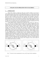
steady state compressible fluid flow in porous media
Bạn đang xem bản rút gọn của tài liệu. Xem và tải ngay bản đầy đủ của tài liệu tại đây (541.21 KB, 35 trang )
Steady State Compressible Fluid Flow in Porous Media 467
Steady State Compressible Fluid Flow in Porous Media
Peter Ohirhian
X
Steady State Compressible Fluid
Flow in Porous Media
Peter Ohirhian
University of Benin, Petroleum Engineering Department
Benin City, Nigeria
Introduction
Darcy showed by experimentation in 1856 that the volumetric flow rate through a porous
sand pack was proportional to the flow rate through the pack. That is:
v
/
K Q
/
K
p
d
pd
==
( i )
(Nutting, 1930) suggested that the proportionality constant in the Darcy law (K
/
) should be
replaced by another constant that depended only on the fluid property. That constant he
called permeability. Thus Darcy law became:
k v
p
d
pd
=
(ii)
Later researches, for example (Vibert, 1939) and (LeRosen, 1942) observed that the Darcy
law was restricted to laminar (viscous) flow.
(Muskat, 1949) among other later researchers suggested that the pressure in the Darcy law
should be replaced with a potential (
). The potential suggested by Muskat is:
gzp
Then Darcy law became:
g
k v
p
d
pd
-
±=
(iii)
(Forchheimer, 1901) tried to extend the Darcy law to non laminar flow by introducing a
second term. His equation is:
20
www.intechopen.com
Natural Gas468
2
v - g
k v
p
d
pd
-
±=
( iv )
(Brinkman, 1947) tried to extend the Darcy equation to non viscous flow by adding a term
borrowed from the Navier Stokes equation. Brinkman equation takes the form:
2
p
d
v
2
d
/
g
k v
p
d
pd
-
+±=
(v)
In 2003, Belhaj et al. re- examined the equations for non viscous flow in porous media. The
authors observed that; neither the Forchheimer equation nor the Brinkman equation used
alone can accurately predict the pressure gradients encountered in non viscous flow,
through porous media. According to the authors, relying on the Brinkman equation alone
can lead to underestimation of pressure gradients, whereas using Forchheimer equation can
lead to overestimation of pressure gradients. Belhaj et al combined all the terms in the Darcy
, Forchheimer and Brinkman equations together with a new term they borrowed from the
Navier Stokes equation to form a new model. Their equation can be written as:
p
d
vdv
- g
2
v
k
v
-
2
p
d
v
2
d
p
d
pd
+=
( vi )
In this work, a cylindrical homogeneous porous medium is considered similar to a pipe. The
effective cross sectional area of the porous medium is taken as the cross sectional area of a
pipe multiplied by the porosity of the medium. With this approach the laws of fluid
mechanics can easily be applied to a porous medium. Two differential equations for gas
flow in porous media were developed. The first equation was developed by combining
Euler equation for the steady flow of any fluid with the Darcy equation; shown by
(Ohirhian, 2008) to be an incomplete expression for the lost head during laminar (viscous)
flow in porous media and the equation of continuity for a real gas. The Darcy law as
presented in the API code 27 was shown to be a special case of this differential equation. The
second equation was derived by combining the Euler equation with the a modification of
the Darcy-Weisbach equation that is known to be valid for the lost head during laminar and
non laminar flow in pipes and the equation of continuity for a real gas.
Solutions were provided to the differential equations of this work by the Runge- Kutta
algorithm. The accuracy of the first differential equation (derived by the combination of the
Darcy law, the equation of continuity for a real gas and the Euler equation) was tested by
data from the book of (Amyx et al., 1960). The book computed the permeability of a certain
porous core as 72.5 millidracy while the solution to the first equation computed it as 72.56
millidarcy. The only modification made to the Darcy- Weisbach formula (for the lost head in
a pipe) so that it could be applied to a porous medium was the replacement of the diameter
of the pipe with the product of the pipe diameter and the porosity of the medium. Thus the
solution to the second differential equation could be used for both pipe and porous
medium. The solution to the second differential equation was tested by using it to calculate
the dimensionless friction factor for a pipe (f) with data taken from the book of (Giles et al.,
2009). The book had f = 0.0205, while the solution to the second differential equation
obtained it as 0.02046. Further, the dimensionless friction factor for a certain core (f
p
)
calculated by the solution to the second differential equation plotted very well in a graph of
f
p
versus the Reynolds number for porous media that was previously generated by
(Ohirhian, 2008) through experimentation.
Development of Equations
The steps used in the development of the general differential equation for the steady flow of
gas pipes can be used to develop a general differential equation for the flow of gas in porous
media. The only difference between the cylindrical homogenous porous medium lies in the
lost head term.
The equations to be combined are;
(a) Euler equation for the steady flow of any fluid.
(b) The equation for lost head
(c) Equation of continuity for a gas.
The Euler equation is:
dp
vdv
d dh
p
l
g
sin 0
(1)
In equation (1), the positive sign (+) before
sind
p
corresponds to the upward direction
of the positive z coordinate and the negative sign (-) to the downward direction of the
positive z coordinate. In other words, the plus sign before
sind
p
is used for uphill flow
and the negative sign is used for downhill flow.
The Darcy-Weisbach equation as modified by (Ohirhian, 2008) (that is applicable to laminar
and non laminar flow) for the lost head in isotropic porous medium is:
c v d
p
dh
L
k
/
(2)
The (Ohirhian, 2008) equation (that is limited to laminar flow) for the lost head in an
isotropic porous medium is;
c v d
p
dh
L
d
p
32
2
(3)
www.intechopen.com
Steady State Compressible Fluid Flow in Porous Media 469
2
v - g
k v
p
d
pd
-
±=
( iv )
(Brinkman, 1947) tried to extend the Darcy equation to non viscous flow by adding a term
borrowed from the Navier Stokes equation. Brinkman equation takes the form:
2
p
d
v
2
d
/
g
k v
p
d
pd
-
+±=
(v)
In 2003, Belhaj et al. re- examined the equations for non viscous flow in porous media. The
authors observed that; neither the Forchheimer equation nor the Brinkman equation used
alone can accurately predict the pressure gradients encountered in non viscous flow,
through porous media. According to the authors, relying on the Brinkman equation alone
can lead to underestimation of pressure gradients, whereas using Forchheimer equation can
lead to overestimation of pressure gradients. Belhaj et al combined all the terms in the Darcy
, Forchheimer and Brinkman equations together with a new term they borrowed from the
Navier Stokes equation to form a new model. Their equation can be written as:
p
d
vdv
- g
2
v
k
v
-
2
p
d
v
2
d
p
d
pd
+=
( vi )
In this work, a cylindrical homogeneous porous medium is considered similar to a pipe. The
effective cross sectional area of the porous medium is taken as the cross sectional area of a
pipe multiplied by the porosity of the medium. With this approach the laws of fluid
mechanics can easily be applied to a porous medium. Two differential equations for gas
flow in porous media were developed. The first equation was developed by combining
Euler equation for the steady flow of any fluid with the Darcy equation; shown by
(Ohirhian, 2008) to be an incomplete expression for the lost head during laminar (viscous)
flow in porous media and the equation of continuity for a real gas. The Darcy law as
presented in the API code 27 was shown to be a special case of this differential equation. The
second equation was derived by combining the Euler equation with the a modification of
the Darcy-Weisbach equation that is known to be valid for the lost head during laminar and
non laminar flow in pipes and the equation of continuity for a real gas.
Solutions were provided to the differential equations of this work by the Runge- Kutta
algorithm. The accuracy of the first differential equation (derived by the combination of the
Darcy law, the equation of continuity for a real gas and the Euler equation) was tested by
data from the book of (Amyx et al., 1960). The book computed the permeability of a certain
porous core as 72.5 millidracy while the solution to the first equation computed it as 72.56
millidarcy. The only modification made to the Darcy- Weisbach formula (for the lost head in
a pipe) so that it could be applied to a porous medium was the replacement of the diameter
of the pipe with the product of the pipe diameter and the porosity of the medium. Thus the
solution to the second differential equation could be used for both pipe and porous
medium. The solution to the second differential equation was tested by using it to calculate
the dimensionless friction factor for a pipe (f) with data taken from the book of (Giles et al.,
2009). The book had f = 0.0205, while the solution to the second differential equation
obtained it as 0.02046. Further, the dimensionless friction factor for a certain core (f
p
)
calculated by the solution to the second differential equation plotted very well in a graph of
f
p
versus the Reynolds number for porous media that was previously generated by
(Ohirhian, 2008) through experimentation.
Development of Equations
The steps used in the development of the general differential equation for the steady flow of
gas pipes can be used to develop a general differential equation for the flow of gas in porous
media. The only difference between the cylindrical homogenous porous medium lies in the
lost head term.
The equations to be combined are;
(a) Euler equation for the steady flow of any fluid.
(b) The equation for lost head
(c) Equation of continuity for a gas.
The Euler equation is:
dp
vdv
d dh
p
l
g
sin 0
(1)
In equation (1), the positive sign (+) before
sind
p
corresponds to the upward direction
of the positive z coordinate and the negative sign (-) to the downward direction of the
positive z coordinate. In other words, the plus sign before
sind
p
is used for uphill flow
and the negative sign is used for downhill flow.
The Darcy-Weisbach equation as modified by (Ohirhian, 2008) (that is applicable to laminar
and non laminar flow) for the lost head in isotropic porous medium is:
c v d
p
dh
L
k
/
(2)
The (Ohirhian, 2008) equation (that is limited to laminar flow) for the lost head in an
isotropic porous medium is;
c v d
p
dh
L
d
p
32
2
(3)
www.intechopen.com
Natural Gas470
The Darcy-Weisbach equation as modified by (Ohirhian, 2008) (applicable to laminar and
non-laminar flow) for the lost head in isotropic porous medium is;
f v d
p
p
dh
L
g d
p
2
2
(4)
The Reynolds number as modified by (Ohirhian, 2008) for an isotropic porous medium is:
pN
R
g
dv
p
=
p
dg
Q4
W
g
d
p
4
(5)
In some cases, the volumetric rate (Q) is measured at a base pressure and a base
temperature. Let us denote the volumetric rate measured at a base pressure (P
b
) and a base
temperature (T
b
) then,
W =
b
Q
b
The Reynolds number can be written in terms of
b
and
b
Q
as
Q
b b
R
N p
g d
p
4
(6)
If the fluid is a gas, the specific weight at P
b
and T
b
is
g
p M
b
b
z T R
b b
A
lso, M 28.97 G , then:
G p
g
b
b
z T R
b b
28.97
Substitution of
b
in equation (4.8) into equation (4.6) leads to:
G P Q
g
b
b
R
NP
Rgd z T
p g
b
b
36.88575
(9)
(7)
(8)
Example 1
In a routine permeability measurement of a cylindrical core sample, the following data were
obtained:
Flow rate of air = 2 cm
2
/ sec
Pressure upstream of core = 1.45 atm
absolute
Pressure downstream of core = 1.00 atm
absolute
Flowing temperature = 70
F
Viscosity of air at flowing temperature = 0.02
cp
Cross sectional area of core = 2 cm
2
Length of core = 2 cm
Porosity of core = 0.2
Find the Reynolds number of the core
Solution
Let us use the pounds seconds feet (p s f) consistent set units. Then substitution of values
into
R
b
T
b
z
M
b
p
b
=
gives:
sec /
3
ft 5 - e 7.062934
sec /
3
ft 5 -E 3.531467 2 sec /
3
cm 2
b
Q
3
ft / b 0.0748
15455301
97.281447.14
b
=
×==
=
××
××
=
b
Q
b
W =
sec/ b 6 - E 5.289431
sec /
3
ft 5 - e 7.062934
3
ft / b 0.0748
=
×=
2
ft / sec / b 7 - E 177086.4
2
ft / sec / b 2.0885430.02 cp 0.02
=
×==
cm 0.713650 0.221.128379
p
A 1.128379
p
d then,.,
4
2
p
d
p
A
=×=
==
= 0. 0 23414 ft
www.intechopen.com
Steady State Compressible Fluid Flow in Porous Media 471
The Darcy-Weisbach equation as modified by (Ohirhian, 2008) (applicable to laminar and
non-laminar flow) for the lost head in isotropic porous medium is;
f v d
p
p
dh
L
g d
p
2
2
(4)
The Reynolds number as modified by (Ohirhian, 2008) for an isotropic porous medium is:
pN
R
g
dv
p
=
p
dg
Q4
W
g
d
p
4
(5)
In some cases, the volumetric rate (Q) is measured at a base pressure and a base
temperature. Let us denote the volumetric rate measured at a base pressure (P
b
) and a base
temperature (T
b
) then,
W =
b
Q
b
The Reynolds number can be written in terms of
b
and
b
Q
as
Q
b b
R
N p
g d
p
4
(6)
If the fluid is a gas, the specific weight at P
b
and T
b
is
g
p M
b
b
z T R
b b
A
lso, M 28.97 G , then:
G p
g
b
b
z T R
b b
28.97
Substitution of
b
in equation (4.8) into equation (4.6) leads to:
G P Q
g
b
b
R
NP
Rgd z T
p g
b
b
36.88575
(9)
(7)
(8)
Example 1
In a routine permeability measurement of a cylindrical core sample, the following data were
obtained:
Flow rate of air = 2 cm
2
/ sec
Pressure upstream of core = 1.45 atm
absolute
Pressure downstream of core = 1.00 atm
absolute
Flowing temperature = 70
F
Viscosity of air at flowing temperature = 0.02
cp
Cross sectional area of core = 2 cm
2
Length of core = 2 cm
Porosity of core = 0.2
Find the Reynolds number of the core
Solution
Let us use the pounds seconds feet (p s f) consistent set units. Then substitution of values
into
R
b
T
b
z
M
b
p
b
=
gives:
sec /
3
ft 5 - e 7.062934
sec /
3
ft 5 -E 3.531467 2 sec /
3
cm 2
b
Q
3
ft / b 0.0748
15455301
97.281447.14
b
=
×==
=
××
××
=
b
Q
b
W =
sec/ b 6 - E 5.289431
sec /
3
ft 5 - e 7.062934
3
ft / b 0.0748
=
×=
2
ft / sec / b 7 - E 177086.4
2
ft / sec / b 2.0885430.02 cp 0.02
=
×==
cm 0.713650 0.221.128379
p
A 1.128379
p
d then,.,
4
2
p
d
p
A
=×=
==
= 0. 0 23414 ft
www.intechopen.com
Natural Gas472
NP
R Then =
=
p
dg
W4
21.385242
0.02341 7- E 177086.42.32
6 - E 289431.54
=
×××
×
Alternatively
.
b
T
b
z
gp
Rgd
b
Q
b
P
g
G88575.36
NP
R
=
=
0.02341453017 - E 177086.42.32
5 - E 052934.71447.141885750.36
××××
××××
=
21.385221
The equation of continuity for gas flow in a pipe is:
===
2
v
2
A
21
v
1
A
1
W
Constant (10)
Then,
A v. W =
In a cylindrical homogeneous porous medium the equation of the weight flow rate can be
written as:
W A v.
p
(11)
Equation (11) can be differentiated and solved simultaneously with the lost head formulas
(equation 2, 3 and 4), and the energy equation (equation 1) to arrive at the general
differential equation for fluid flow in a homogeneous porous media.
Regarding the cross sectional area of the porous medium (A
p
) as a constant, equation (11)
can be differentiated and solve simultaneously with equations (2) and (1) to obtain.
_
c v
sin
k
d p
d
p
d
W
d p
A g
p
/
2
1
2 2
(12)
Equation (12) is a differential equation that is valid for the laminar flow of any fluid in a
homogeneous porous medium. The fluid can be a liquid of constant compressibility or a gas.
The negative sign that proceeds the numerator of equation (12) shows that pressure
decreases with increasing length of porous media.
The compressibility of a fluid (C
f
) is defined as:
d
1
C
f
d p
(13)
Combination of equations (12) and (13 ) leads to:
_
c v
sin
k
d p
d
p
W
A g
p
/
2
1
2
(14)
Differentiation of equation (11) and simultaneous solution with equations (2), (1) and (13)
after some simplifications, produces:
_
c v
sin
2
d
p
d p
d
p
W C
f
A g
p
32
2
1
2
(15)
Differentiation of equation (6) and simultaneous solution with equations (4), (1) and ( 1 3)
after some simplifications produces:
2
f W
p
sin
2
2 A d
p p
d p
d
p
W C
f
A g
p
2
1
2
-
(16)
Equation (16) can be simplified further for gas flow through homogeneous porous media.
The cross sectional area of a cylindrical cross medium is:
p
A
d
p
2
4
(17)
www.intechopen.com
Steady State Compressible Fluid Flow in Porous Media 473
NP
R Then =
=
p
dg
W4
21.385242
0.02341 7- E 177086.42.32
6 - E 289431.54
=
×××
×
Alternatively
.
b
T
b
z
gp
Rgd
b
Q
b
P
g
G88575.36
NP
R
=
=
0.02341453017 - E 177086.42.32
5 - E 052934.71447.141885750.36
××××
××××
=
21.385221
The equation of continuity for gas flow in a pipe is:
===
2
v
2
A
21
v
1
A
1
W
Constant (10)
Then,
A v. W
=
In a cylindrical homogeneous porous medium the equation of the weight flow rate can be
written as:
W A v.
p
(11)
Equation (11) can be differentiated and solved simultaneously with the lost head formulas
(equation 2, 3 and 4), and the energy equation (equation 1) to arrive at the general
differential equation for fluid flow in a homogeneous porous media.
Regarding the cross sectional area of the porous medium (A
p
) as a constant, equation (11)
can be differentiated and solve simultaneously with equations (2) and (1) to obtain.
_
c v
sin
k
d p
d
p
d
W
d p
A g
p
/
2
1
2 2
(12)
Equation (12) is a differential equation that is valid for the laminar flow of any fluid in a
homogeneous porous medium. The fluid can be a liquid of constant compressibility or a gas.
The negative sign that proceeds the numerator of equation (12) shows that pressure
decreases with increasing length of porous media.
The compressibility of a fluid (C
f
) is defined as:
d
1
C
f
d p
(13)
Combination of equations (12) and (13 ) leads to:
_
c v
sin
k
d p
d
p
W
A g
p
/
2
1
2
(14)
Differentiation of equation (11) and simultaneous solution with equations (2), (1) and (13)
after some simplifications, produces:
_
c v
sin
2
d
p
d p
d
p
W C
f
A g
p
32
2
1
2
(15)
Differentiation of equation (6) and simultaneous solution with equations (4), (1) and ( 1 3)
after some simplifications produces:
2
f W
p
sin
2
2 A d
p p
d p
d
p
W C
f
A g
p
2
1
2
-
(16)
Equation (16) can be simplified further for gas flow through homogeneous porous media.
The cross sectional area of a cylindrical cross medium is:
p
A
d
p
2
4
(17)
www.intechopen.com
Natural Gas474
The equation of state for a non ideal gas is:
p
M
z T R
(18)
Where
=p
Absolute pressure
=T
Absolute temperature
Multiply equation (11) with
and substitute A
p
in equation (17) and use the fact that:
p
d
2
pd
2
1
p
d
pdp
=
Then
_
f W zR
p
zR
d g
d
d
W zR C
p
f
g d
2
2
2 sin
1.621139
5
2
2
1.621139
1
4
(19)
The compressibility of ideal gas
g
C
is defined as
z
C .
g
p
z p
1 1
_
(20)
For an ideal gas such as air,
C .
g
p
1
(21)
(Matter et al, 1975) and ( Ohirhian, 2008) have proposed equations for the calculation of the
compressibility of hydrocarbon gases. For a sweet natural gas (natural gas that contains CO
2
as major contaminant), (Ohirhian, 2008) has expressed the compressibility of the real gas
(C
g
) as:
p
f
C
Κ
=
(22)
For Nigerian (sweet) natural gas K = 1.0328 when p is in psia. Then equation (19) can then
be written compactly as:
_
AAp B p
d p
p
C
d
p
p
p
2
2
( )
(1 )
2
(23)
Where
4
p
gMd
zRT
2
KW
p
C
,
zRT
sinM2
p
B ,
M
5
p
gd
zRT
2
W
p
f621139.1
p
AA
=
==
The denominator of the differential equation (23) is the contribution of kinetic effect to the
pressure drop across a given length of a cylindrical isotropic porous medium. In a pipe the
kinetic contribution to the pressure drop is very small and can be neglected. What of a
homogeneous porous medium?
Kinetic Effect in Pipe and Porous Media
An evaluation of the kinetic effect can be made if values are substituted into the variables
that occurs in the denominator of the differential equation (23)
Example 2
Calculate the kinetic energy correction factor, given that 0.75 pounds per second of air
flow isothermally through a 4 inch pipe at a pressure of 49.5 psia and temperature of 90 0 F.
Solution
The kinetic effect correction factor is
2
p
C
_
1
Where C for a pipe is given by,
4
gMd
zRT
2
KW
C =
Here
sec/lb75.0W = , ft 0.333333 ft 12/4inch4d === ,
psf 7128 psf 44 49.5 psia 45.5 p =×==
, R550R)46090( F
o
90 T °=°+==
, fluid) theis(air 1.0 z =
2
secft / 32.2 g ,1545R ==
, 28.97 M =
.
Then,
58628.41504
4
333333.097.282.32
55015451
2
75.01
C =
××
××××
=
, gas idealan for 1 K =
www.intechopen.com
Steady State Compressible Fluid Flow in Porous Media 475
The equation of state for a non ideal gas is:
p
M
z T R
(18)
Where
=p
Absolute pressure
=T
Absolute temperature
Multiply equation (11) with
and substitute A
p
in equation (17) and use the fact that:
p
d
2
pd
2
1
p
d
pdp
=
Then
_
f W zR
p
zR
d g
d
d
W zR C
p
f
g d
2
2
2 sin
1.621139
5
2
2
1.621139
1
4
(19)
The compressibility of ideal gas
g
C
is defined as
z
C .
g
p
z p
1 1
_
(20)
For an ideal gas such as air,
C .
g
p
1
(21)
(Matter et al, 1975) and ( Ohirhian, 2008) have proposed equations for the calculation of the
compressibility of hydrocarbon gases. For a sweet natural gas (natural gas that contains CO
2
as major contaminant), (Ohirhian, 2008) has expressed the compressibility of the real gas
(C
g
) as:
p
f
C
Κ
=
(22)
For Nigerian (sweet) natural gas K = 1.0328 when p is in psia. Then equation (19) can then
be written compactly as:
_
AAp B p
d p
p
C
d
p
p
p
2
2
( )
(1 )
2
(23)
Where
4
p
gMd
zRT
2
KW
p
C
,
zRT
sinM2
p
B ,
M
5
p
gd
zRT
2
W
p
f621139.1
p
AA
=
==
The denominator of the differential equation (23) is the contribution of kinetic effect to the
pressure drop across a given length of a cylindrical isotropic porous medium. In a pipe the
kinetic contribution to the pressure drop is very small and can be neglected. What of a
homogeneous porous medium?
Kinetic Effect in Pipe and Porous Media
An evaluation of the kinetic effect can be made if values are substituted into the variables
that occurs in the denominator of the differential equation (23)
Example 2
Calculate the kinetic energy correction factor, given that 0.75 pounds per second of air
flow isothermally through a 4 inch pipe at a pressure of 49.5 psia and temperature of 90 0 F.
Solution
The kinetic effect correction factor is
2
p
C
_
1
Where C for a pipe is given by,
4
gMd
zRT
2
KW
C =
Here
sec/lb75.0W = , ft 0.333333 ft 12/4inch4d === ,
psf 7128 psf 44 49.5 psia 45.5 p =×==
, R550R)46090( F
o
90 T °=°+==
, fluid) theis(air 1.0 z =
2
secft / 32.2 g ,1545R ==
, 28.97 M =
.
Then,
58628.41504
4
333333.097.282.32
55015451
2
75.01
C =
××
××××
=
, gas idealan for 1 K =
www.intechopen.com
Natural Gas476
The kinetic effect correction factor is
999183.0
2
7128
58628.41504
_
1
2
p
C
_
1 ==
Example 3
If the pipe in example 1 were to be a cylindrical homogeneous porous medium of 25 %
porosity, what would be the kinetic energy correction factor?
Solution
Here, d
p =
d = 333333.0 25.0 = ft1666667.0
0212.344046
4
166667.097.282.32
55015451
2
75.01
p
C
=
××
××××
=
Then,
993221.0
2
7128
0212.3441046
1
2
p
p
C
_
1 ==
The kinetic effect is also small, though not as small as that of a pipe. The higher the pressure,
the more negligible the kinetic energy correction factor. For example, at 100 psia, the kinetic
energy correction factor in example 2 is:
998341.0
2
)144100(
0212.3441046
_
1 =
×
Simplification of the Differential Equations for Porous Media
When the kinetic effect is ignored, the differential equations for porous media can be
simplified. Equation (14) derived with the Darcy form of the lost head becomes:
d
c v
p
sin
d k
p
/
(24)
Equation (15) derived with the (Ohirhian, 2008) form of the lost head becomes:
d p c v
sin
2
d
d
p
p
32
(25)
Equation (16) derived with the (Ohirhian, 2008) modification of the Darcy- Weisbach lost
head becomes:
2
f W
d p
p
sin
2
d
p
2 A d
p p
(26)
In terms of velocity (v) equation (26) can be written as:
2
f v
d p
p
sin
d 2 d
p p
(27)
In certain derivations (for example, reservoir simulation models) it is required to make v or
W subject of equations (24) to (27)
Making velocity (v) or weight (W) subject of the simplified differential equations
When v is made subject of equation (24), we obtain:
d p
- k
v sin
/
d
c
p
(28)
When v is made subject of equation (25), we obtain:
- d
p d p
v sin
32c d
p
2
(29)
When v
2
is made subject of equation (27), we obtain:
- 2 g d
p d p
v sin
f d
p p
2
(30)
When W
2
is made subject of equation (26), we obtain:
- 2 g d A
p
p d p
W sin
f d
p p
2
2
(31)
Let S be the direction of flow which is always positive, then equation (28) can be written as:
d p
d z
- k
v
s
ds d s
_ 6
10
1.01325
(32)
Where:
www.intechopen.com
Steady State Compressible Fluid Flow in Porous Media 477
The kinetic effect correction factor is
999183.0
2
7128
58628.41504
_
1
2
p
C
_
1 ==
Example 3
If the pipe in example 1 were to be a cylindrical homogeneous porous medium of 25 %
porosity, what would be the kinetic energy correction factor?
Solution
Here, d
p = d = 333333.0 25.0 = ft1666667.0
0212.344046
4
166667.097.282.32
55015451
2
75.01
p
C
=
××
××××
=
Then,
993221.0
2
7128
0212.3441046
1
2
p
p
C
_
1 ==
The kinetic effect is also small, though not as small as that of a pipe. The higher the pressure,
the more negligible the kinetic energy correction factor. For example, at 100 psia, the kinetic
energy correction factor in example 2 is:
998341.0
2
)144100(
0212.3441046
_
1 =
×
Simplification of the Differential Equations for Porous Media
When the kinetic effect is ignored, the differential equations for porous media can be
simplified. Equation (14) derived with the Darcy form of the lost head becomes:
d
c v
p
sin
d k
p
/
(24)
Equation (15) derived with the (Ohirhian, 2008) form of the lost head becomes:
d p c v
sin
2
d
d
p
p
32
(25)
Equation (16) derived with the (Ohirhian, 2008) modification of the Darcy- Weisbach lost
head becomes:
2
f W
d p
p
sin
2
d
p
2 A d
p p
(26)
In terms of velocity (v) equation (26) can be written as:
2
f v
d p
p
sin
d 2 d
p p
(27)
In certain derivations (for example, reservoir simulation models) it is required to make v or
W subject of equations (24) to (27)
Making velocity (v) or weight (W) subject of the simplified differential equations
When v is made subject of equation (24), we obtain:
d p
- k
v sin
/
d
c
p
(28)
When v is made subject of equation (25), we obtain:
- d
p d p
v sin
32c d
p
2
(29)
When v
2
is made subject of equation (27), we obtain:
- 2 g d
p d p
v sin
f d
p p
2
(30)
When W
2
is made subject of equation (26), we obtain:
- 2 g d A
p
p d p
W sin
f d
p p
2
2
(31)
Let S be the direction of flow which is always positive, then equation (28) can be written as:
d p
d z
- k
v
s
ds d s
_ 6
10
1.01325
(32)
Where:
www.intechopen.com
Natural Gas478
s
v Volumetric flux across a unit area of
porous medium in unit time along
flow path, S cm / sec
2
sec / cm 980.605 gravity, todueon Accelerati g
cc / mass gm , fluid ofDensity Mass
cc weight / gm , fluid of weight Specificg
=
=
==
cm / atm refers,
s
which v
point to at the S alonggradient Pressure
sd
pd
=
atm cm sq / dynes
6
10 1.01325
darcys. medium, theofty Permeabili k
cm downwards,
positive considered ,coordinate Vertical z
scentipoise fluid, theofViscosity
=×
=
=
=
According to (Amyx et al., 1960), this is “the generalized form of Darcy law as presented in
APT code 27 “.
Horizontal and Uphill Gas Flow in Porous Media
In uphill flow, the + sign in the numerator of equation (23) is used. Neglecting the kinetic
effect, which is small, equation (23) becomes
dp
A
A B
p
P P
d
p
2
2
(33)
zTR
2Msinθ
p
B
,
M
5
p
gd
2
zTRW
p
1.621139f
p
AA
=
=
An equation similar to equation (33) can also be derived if the Darcian lost head is used. The
horizontal / uphill gas flow equation in porous media becomes.
Where
Mk
2
p
d
zTRWc546479.2
Mk
2
2
d
zTRWc8
Mk
p
A
zTRWc2
/
p
AA
′
=
′
=
′
=
Solution to the Horizontal/Uphill Flow Equation
Differential equations (33) and (34) are of the first order and can be solved by the classical
Runge - Kutta algorithm. The Runge - Kutta algorithm used in this work came from book of
(Aires, 1962) called “Theory and problems of Differential equations”. The Runge - Kutta
solution to the differential equation
( )
given that xat x y,xf
dx
dy
n
==
is x x at
0
y y
0
==
y
y
k k k k
1
2( )
0 1 2 3 4
6
(35)
where
k Hf x y
o o
k H
f
x H
y
k
o
k H
f
x H
y
k
o o
k Hf x H y k
o
x x
n o
H
n
n sub ervals steps
( , )
1
1 1
( , )
2 0 1
2 2
1 1
( , )
3 1
2 2
( , )
4 0 3
int ( )
Application of the Runge - Kutta algorithm to equation (33) leads to:
dp
AA B p
p
p
d
p
2
/
2
(34)
www.intechopen.com
Steady State Compressible Fluid Flow in Porous Media 479
s
v Volumetric flux across a unit area of
porous medium in unit time along
flow path, S cm / sec
2
sec / cm 980.605 gravity, todueon Accelerati g
cc / mass gm , fluid ofDensity Mass
cc weight / gm , fluid of weight Specificg
=
=
==
cm / atm refers,
s
which v
point to at the S alonggradient Pressure
sd
pd
=
atm cm sq / dynes
6
10 1.01325
darcys. medium, theofty Permeabili k
cm downwards,
positive considered ,coordinate Vertical z
scentipoise fluid, theofViscosity
=×
=
=
=
According to (Amyx et al., 1960), this is “the generalized form of Darcy law as presented in
APT code 27 “.
Horizontal and Uphill Gas Flow in Porous Media
In uphill flow, the + sign in the numerator of equation (23) is used. Neglecting the kinetic
effect, which is small, equation (23) becomes
dp
A
A B
p
P P
d
p
2
2
(33)
zTR
2Msinθ
p
B
,
M
5
p
gd
2
zTRW
p
1.621139f
p
AA
=
=
An equation similar to equation (33) can also be derived if the Darcian lost head is used. The
horizontal / uphill gas flow equation in porous media becomes.
Where
Mk
2
p
d
zTRWc546479.2
Mk
2
2
d
zTRWc8
Mk
p
A
zTRWc2
/
p
AA
′
=
′
=
′
=
Solution to the Horizontal/Uphill Flow Equation
Differential equations (33) and (34) are of the first order and can be solved by the classical
Runge - Kutta algorithm. The Runge - Kutta algorithm used in this work came from book of
(Aires, 1962) called “Theory and problems of Differential equations”. The Runge - Kutta
solution to the differential equation
( )
given that xat x y,xf
dx
dy
n
==
is x x at
0
y y
0
==
y
y
k k k k
1
2( )
0 1 2 3 4
6
(35)
where
k Hf x y
o o
k H
f
x H
y
k
o
k H
f
x H
y
k
o o
k Hf x H y k
o
x x
n o
H
n
n sub ervals steps
( , )
1
1 1
( , )
2 0 1
2 2
1 1
( , )
3 1
2 2
( , )
4 0 3
int ( )
Application of the Runge - Kutta algorithm to equation (33) leads to:
dp
AA B p
p
p
d
p
2
/
2
(34)
www.intechopen.com
Natural Gas480
p
p y
a
2
2 2
1
(36)
Where
( )
3
a
x72.0
2
x48.1x96.4
6
2
2
p
3
a
x36.0
2
a
x5.0
a
x1
a
p
aa
a
y
aa
)(
+++
+++=
+
( )
2
a
x72.0
a
x96.196.4
6
a
p
u
++
)L
2
S
p2
(AA
a
p
aa +=
R
2
T
2
z
2
2
psinM2
2
S
,
M
5
p
gd
2
RW
2
T
2
z
p
f621139.1
2p
AA
=
=
R
av
T
a
av
z
LsinM2
a
x
,
M
5
p
gd
2
RW
av
T
av
z
p
f621139.1
a
p
u
=
=
Where:
p
1
= Pressure at inlet end of porous medium p
2
= Pressure at exit end of porous medium
f
p
= Friction factor of porous medium.
θ = Angle of inclination of porous
medium with horizontal in degrees.
z
2
= Gas deviation factor at exit end of
porous medium.
T
2
= Temperature at exit end of porous
medium
T
1
= Temperature at inlet end of porous
medium
z
a v
= Average gas deviation factor
evaluated with T
a v
and p
a v
T
a v
= Arithmetic average temperature of
the porous medium given by
0.5(T
1
+ T
2
) and
p
a v
a
=
a
p
aa
2
2
p +
In equation (36), the component k
4
in the Runge - Kutta algorithm was given some
weighting to compensate for the variation of temperature (T) and gas deviation factor (z)
between the mid section and the inlet end of the porous medium. In isothermal flow where
there is little variation of the gas deviation factor between the mid section and the inlet end
of the porous medium, the coefficients of x
a
change slightly, then,
( )
)
2
a
x5.0
a
x25(
6
2
p
u
)
3
a
x5.0
2
a
x2
a
x5(
6
2
2
p
3
a
x25.0
2
a
x5.0
a
x1
a
p
aa
a
y
+++
+++
+++=
Application of the Runge-Kutta algorithm to equation (34) produces.
p p y
b
2 2
1 2
(37)
( )
3
b
x36.0
2
b
x5.0
b
x1
b
p
aa
b
y +++=
( )
2
b
x72.0
2
b
x48.1
b
x96.4
6
2
2
p
+++
( )
2
b
x72.0
b
x96.196.4
6
2
p
u
+++
www.intechopen.com
Steady State Compressible Fluid Flow in Porous Media 481
p
p y
a
2
2 2
1
(36)
Where
( )
3
a
x72.0
2
x48.1x96.4
6
2
2
p
3
a
x36.0
2
a
x5.0
a
x1
a
p
aa
a
y
aa
)(
+++
+++=
+
( )
2
a
x72.0
a
x96.196.4
6
a
p
u
++
)L
2
S
p2
(AA
a
p
aa +=
R
2
T
2
z
2
2
psinM2
2
S
,
M
5
p
gd
2
RW
2
T
2
z
p
f621139.1
2p
AA
=
=
R
av
T
a
av
z
LsinM2
a
x
,
M
5
p
gd
2
RW
av
T
av
z
p
f621139.1
a
p
u
=
=
Where:
p
1
= Pressure at inlet end of porous medium p
2
= Pressure at exit end of porous medium
f
p
= Friction factor of porous medium.
θ = Angle of inclination of porous
medium with horizontal in degrees.
z
2
= Gas deviation factor at exit end of
porous medium.
T
2
= Temperature at exit end of porous
medium
T
1
= Temperature at inlet end of porous
medium
z
a v
= Average gas deviation factor
evaluated with T
a v
and p
a v
T
a v
= Arithmetic average temperature of
the porous medium given by
0.5(T
1
+ T
2
) and
p
a v
a
=
a
p
aa
2
2
p +
In equation (36), the component k
4
in the Runge - Kutta algorithm was given some
weighting to compensate for the variation of temperature (T) and gas deviation factor (z)
between the mid section and the inlet end of the porous medium. In isothermal flow where
there is little variation of the gas deviation factor between the mid section and the inlet end
of the porous medium, the coefficients of x
a
change slightly, then,
( )
)
2
a
x5.0
a
x25(
6
2
p
u
)
3
a
x5.0
2
a
x2
a
x5(
6
2
2
p
3
a
x25.0
2
a
x5.0
a
x1
a
p
aa
a
y
+++
+++
+++=
Application of the Runge-Kutta algorithm to equation (34) produces.
p p y
b
2 2
1 2
(37)
(
)
3
b
x36.0
2
b
x5.0
b
x1
b
p
aa
b
y +++=
( )
2
b
x72.0
2
b
x48.1
b
x96.4
6
2
2
p
+++
( )
2
b
x72.0
b
x96.196.4
6
2
p
u
+++
www.intechopen.com
Natural Gas482
Where aa
p
b
=
L )
2
S
/
2p
AA( +
kM
2
p
d
RW
2
T
2
zc546479.2
kM
2
2
d
RW
2
T
2
zc8
kM
p
A
RW
2
T
2
zc2
/
2p
AA
′
=
′
=
′
=
Mk
2
p
d
RW
av
T
b
av
zc2.546479
Mk
P
A
RW
av
T
b
av
zc2
b
p
u ,
R
2
T
2
z
2
2
psinM2
2
S
′
=
′
==
R
av
T
b
av
z
LsinM2
b
x
=
Where
=
b
av
z Average gas deviations factors evaluated with T
a v
and p
a v
b
T
a v
= Arithmetic average Temperature of the porous medium = 0.5(T
1
+T
2
),
aa5.0 p
b
p
2
2
b
va
p
All other variables remain as defined in equation (36). In isothermal flow where there is not
much variation in the gas deviation factor (z) between the mid section and inlet and of the
porous medium there is no need to make compensation in the k
4
parameter in the Runge
Kuta algorithm, then equation (37) becomes:
p p
y
bT
2 2
1 2
(38)
Where:
++++= )
3
b
x5.0
2
b
x25.0
2
b
x5.0
b
x1(
b
p
aa
bT
y
p
x x x
b b b
2 3
2
5 2 0.5
6
b
u
p
x x
b b
2
5 2 0.5
6
Equation (36) can be arranged as:
PU] )
3
c
x36.0
2
c
x5.0
c
x1(
2
T
2
z[
a
p
BB
p
f
2
W ++++
c c c
c c c
2
p
2 2
1
p
- x x x -
p
1 2
6
- S x x x
2
2 2
4.96 1.48 0.72
2 3
1 0.5 0.36
(39)
Where
( )
2
x72.0
2
x48.1x96.4Tz PU
ccc
v
aav
++=
,
R
2
T
2
z
2
2
psinM2
2
S,
M
5
p
dg6
RL621139.1
a
p
BB
==
M L
x
c
c
z T R
av av
2 sin
c
av
z
Average gas deviations factors
evaluated with T
av
and p
av
c
and
2
2
2
p
2
1
p
p
c
av
+
=
All other variables remain as defined in previous equations.
In isothermal flow where there is no significant change in the gas deviation factor (z),
equation (39) becomes:
x x x
c c c
a
W f BB z T
p
P
x x
c c
2 3
(1 0.5 0.25
2
2 2
2
(5 2 0.5 )
)(
)
www.intechopen.com
Steady State Compressible Fluid Flow in Porous Media 483
Where aa
p
b
=
L )
2
S
/
2p
AA( +
kM
2
p
d
RW
2
T
2
zc546479.2
kM
2
2
d
RW
2
T
2
zc8
kM
p
A
RW
2
T
2
zc2
/
2p
AA
′
=
′
=
′
=
Mk
2
p
d
RW
av
T
b
av
zc2.546479
Mk
P
A
RW
av
T
b
av
zc2
b
p
u ,
R
2
T
2
z
2
2
psinM2
2
S
′
=
′
==
R
av
T
b
av
z
LsinM2
b
x
=
Where
=
b
av
z Average gas deviations factors evaluated with T
a v
and p
a v
b
T
a v
= Arithmetic average Temperature of the porous medium = 0.5(T
1
+T
2
),
aa5.0 p
b
p
2
2
b
va
p
All other variables remain as defined in equation (36). In isothermal flow where there is not
much variation in the gas deviation factor (z) between the mid section and inlet and of the
porous medium there is no need to make compensation in the k
4
parameter in the Runge
Kuta algorithm, then equation (37) becomes:
p p
y
bT
2 2
1 2
(38)
Where:
++++= )
3
b
x5.0
2
b
x25.0
2
b
x5.0
b
x1(
b
p
aa
bT
y
p
x x x
b b b
2 3
2
5 2 0.5
6
b
u
p
x x
b b
2
5 2 0.5
6
Equation (36) can be arranged as:
PU] )
3
c
x36.0
2
c
x5.0
c
x1(
2
T
2
z[
a
p
BB
p
f
2
W ++++
c c c
c c c
2
p
2 2
1
p
- x x x -
p
1 2
6
- S x x x
2
2 2
4.96 1.48 0.72
2 3
1 0.5 0.36
(39)
Where
(
)
2
x72.0
2
x48.1x96.4Tz PU
ccc
v
aav
++=
,
R
2
T
2
z
2
2
psinM2
2
S,
M
5
p
dg6
RL621139.1
a
p
BB
==
M L
x
c
c
z T R
av av
2 sin
c
av
z
Average gas deviations factors
evaluated with T
av
and p
av
c
and
2
2
2
p
2
1
p
p
c
av
+
=
All other variables remain as defined in previous equations.
In isothermal flow where there is no significant change in the gas deviation factor (z),
equation (39) becomes:
x x x
c c c
a
W f BB z T
p
P
x x
c c
2 3
(1 0.5 0.25
2
2 2
2
(5 2 0.5 )
)(
)
www.intechopen.com
Natural Gas484
- -
-
p
p x x x p
c c c
S L
x x x
c c c
2
2 2 3 2
1
5 2 0.5
1 2
6
2 3
2
1 0.5 0.25
6
(40)
When the porous medium is horizontal, S
2
= 0 and x
c
= 0 then from equation (40),
-p p
f
p
a
W BB z T z T
p
av av
2 2
1 2
2
4.96
2 2
(41)
In an isothermal flow where there is no variation in z,
p
f
=
2
T
2
z
a
p
BB
2
W6
2
2
p-
2
1
p
(42)
Example 4
The following data came from the book of (Giles et al., 2009) called “theory and problem of
fluid mechanics and hydraulics”
W = 0.75 1b/sec of air, R = 1544, L = 1800ft, d = 4inch = 0.333333ft,
g = 32.2ft/sec
2
, z
2
= z
av
a
= 1 (air is fluid), T
2
= R
0
550 F
0
90
av
T ==
(Isothermal flow), p
1
= 49.5psia = 7128psf, P
2
= 45.73 psia = 6585.12 psf.
Pipe is horizontal.
(a)
Calculate friction factor of the pipe (f)
(b)
If the pipe were to be filled with a homogenous porous material having a porosity
of 20% what would be the friction factor (fp )?
Solution
(a) Let BB
a
the equivalent BB
P
a
by use of a pipe then.
RL
a
BB
gd M
`1.621139
5
6
1195610.824
97.28
5
333333.02.326
18001544621139.1
=
×××
××
=
0.20463
550 11195610.824
2
0.75 6
2
6585.12-
2
7128
2
T
2
z
a
BB
2
W6
2
2
p-
2
1
p
f
=
××××
==
The calculated f agrees with f = 0.0205 obtained by Giles et al., who used another equation.
0.149071ft 0.2ft 333333.0
p
d )b( =×=
62.10934995
97.28
5
1490751.02.326
18001544621139.1
M
5
p
gd6
RL621139.1`
a
p
BB
=
×××
××
=
=
2
T
2
z
a
p
BB
2
W6
2
2
p-
2
1
p
p
f =
4-E 3.667626
550 1 210934995.6
2
0.75 6
2
6585.12-
2
7128
=
××××
=
The equation for pressure transverse in a porous medium by use of Darcian lost head
(equation (37) can be arranged as:
( )
( )
+++
+++
]
[
2
c
x72.0
c
1.96x 96.4
av
T
b
av
z
c
3
x36.0
2
c
x5.0
c
x 1
2
T
2
z
k
b
p
BB
2
W
- -
-
p
p
x x x p
c c
b
S L
x x x
c c c
2
2 2 3 2
1
4.96 1.48 0.36
1 2
6
2 2
2
1 0.5 0.3
6
(43)
Where
,
M
2
p
d6
RLc576479.2
M
p
A6
RLc2
b
p
BB
′
=
′
=
www.intechopen.com
Steady State Compressible Fluid Flow in Porous Media 485
- -
-
p
p x x x p
c c c
S L
x x x
c c c
2
2 2 3 2
1
5 2 0.5
1 2
6
2 3
2
1 0.5 0.25
6
(40)
When the porous medium is horizontal, S
2
= 0 and x
c
= 0 then from equation (40),
-p p
f
p
a
W BB z T z T
p
av av
2 2
1 2
2
4.96
2 2
(41)
In an isothermal flow where there is no variation in z,
p
f
=
2
T
2
z
a
p
BB
2
W6
2
2
p-
2
1
p
(42)
Example 4
The following data came from the book of (Giles et al., 2009) called “theory and problem of
fluid mechanics and hydraulics”
W = 0.75 1b/sec of air, R = 1544, L = 1800ft, d = 4inch = 0.333333ft,
g = 32.2ft/sec
2
, z
2
= z
av
a
= 1 (air is fluid), T
2
= R
0
550 F
0
90
av
T ==
(Isothermal flow), p
1
= 49.5psia = 7128psf, P
2
= 45.73 psia = 6585.12 psf.
Pipe is horizontal.
(a)
Calculate friction factor of the pipe (f)
(b)
If the pipe were to be filled with a homogenous porous material having a porosity
of 20% what would be the friction factor (fp )?
Solution
(a) Let BB
a
the equivalent BB
P
a
by use of a pipe then.
RL
a
BB
gd M
`1.621139
5
6
1195610.824
97.28
5
333333.02.326
18001544621139.1
=
×××
××
=
0.20463
550 11195610.824
2
0.75 6
2
6585.12-
2
7128
2
T
2
z
a
BB
2
W6
2
2
p-
2
1
p
f
=
××××
==
The calculated f agrees with f = 0.0205 obtained by Giles et al., who used another equation.
0.149071ft 0.2ft 333333.0
p
d )b( =×=
62.10934995
97.28
5
1490751.02.326
18001544621139.1
M
5
p
gd6
RL621139.1`
a
p
BB
=
×××
××
=
=
2
T
2
z
a
p
BB
2
W6
2
2
p-
2
1
p
p
f =
4-E 3.667626
550 1 210934995.6
2
0.75 6
2
6585.12-
2
7128
=
××××
=
The equation for pressure transverse in a porous medium by use of Darcian lost head
(equation (37) can be arranged as:
(
)
( )
+++
+++
]
[
2
c
x72.0
c
1.96x 96.4
av
T
b
av
z
c
3
x36.0
2
c
x5.0
c
x 1
2
T
2
z
k
b
p
BB
2
W
- -
-
p
p
x x x p
c c
b
S L
x x x
c c c
2
2 2 3 2
1
4.96 1.48 0.36
1 2
6
2 2
2
1 0.5 0.3
6
(43)
Where
,
M
2
p
d6
RLc576479.2
M
p
A6
RLc2
b
p
BB
′
=
′
=
www.intechopen.com
Natural Gas486
R
2
T
2
z
2
2
P sinM2
2
S
=
R
av
T
c
av
z
L sinM2
c
x
=
z
a v
c
=
Average gas deviation factor calculated with p
a v
c
and T
a v
p
a v
c
=
2
p p
2
2
2
1
When the porous medium is horizontal, S
2
= 0, , and x
c
= 0, then ,
-p p
c
b
W BB z T 4.96 z T
p
av av
k
2 2
1 2
2
2 2
(44)
When the flow is isothermal and there is no significant variation in the gas deviation factor
(z) equation (44) becomes.
+++
+++
]
[
)
2
c
x5.0
c
2x 5(
2
T
2
z
)
c
3
x25.0
2
c
x5.0
c
x 1(
2
T
2
z
k
b
p
BB
2
W
- -
-
p
p x x x
c c c
S L
x x x
c c c
p
2
2 2 3 2
1
5 2 0.5
1 2
6
2 2
2
1 0.5 0.25
6
[
]
(45)
When the porous medium is horizontal, equation (45) becomes
-
b
WBB z T
p
k
p p
6
2 2
2 2
1 2
(46)
Example 5
The following problem came from the book of (Amyx et al., 1960). During a routine
permeability test, the following data were obtained.
Flow rate (Q) = 1,000cc
of air in 500sec.
Pressure down stream of core (p
2
) = 1 atm. absolute
Flowing temperature (T) = 70
0
F
Viscosity or air at test temperature (μ) = 0.02c
p
Cross-sectional area of core (A
p
) = 2cm
2
Pressure upstream of core (p
1
) = 1.45 atm absolute
Length of core (L
p
) = 2cm
Compute the permeability of the core in millidarcy
Solution
In oil field units in which pressure is in atmospheres and temperature is expressed in degree
Kelvin, R = 82.1
Here, T = 70
0
F = (70 + 460)
0
R =
8.1
R
0
530
K
0
4.294=
Q =
cc cc1000 / 500 sec 2 / sec
c
z z z 1 (air is fluid )
av1 2
The volumetric flow rate can be converted to weight flow rate by:
W=
Q where
=
p
M
zTR
Substituting given values
W
gm
1 28.97 2
1 82.1 294.4
0.002397163 /sec
Taking the core to be horizontal
where
pp
2
T
2
z
b
P
wBB6
k
2
2
2
1
) units ofset consistent ain 1c( ,
MA6
RL2
BB
p
p
b
2
_
E889311.1
97.2826
21.8202.02
=
××
×××
=
www.intechopen.com
Steady State Compressible Fluid Flow in Porous Media 487
R
2
T
2
z
2
2
P sinM2
2
S
=
R
av
T
c
av
z
L sinM2
c
x
=
z
a v
c
=
Average gas deviation factor calculated with p
a v
c
and T
a v
p
a v
c
=
2
p p
2
2
2
1
When the porous medium is horizontal, S
2
= 0, , and x
c
= 0, then ,
-p p
c
b
W BB z T 4.96 z T
p
av av
k
2 2
1 2
2
2 2
(44)
When the flow is isothermal and there is no significant variation in the gas deviation factor
(z) equation (44) becomes.
+++
+++
]
[
)
2
c
x5.0
c
2x 5(
2
T
2
z
)
c
3
x25.0
2
c
x5.0
c
x 1(
2
T
2
z
k
b
p
BB
2
W
- -
-
p
p x x x
c c c
S L
x x x
c c c
p
2
2 2 3 2
1
5 2 0.5
1 2
6
2 2
2
1 0.5 0.25
6
[
]
(45)
When the porous medium is horizontal, equation (45) becomes
-
b
WBB z T
p
k
p p
6
2 2
2 2
1 2
(46)
Example 5
The following problem came from the book of (Amyx et al., 1960). During a routine
permeability test, the following data were obtained.
Flow rate (Q) = 1,000cc
of air in 500sec.
Pressure down stream of core (p
2
) = 1 atm. absolute
Flowing temperature (T) = 70
0
F
Viscosity or air at test temperature (μ) = 0.02c
p
Cross-sectional area of core (A
p
) = 2cm
2
Pressure upstream of core (p
1
) = 1.45 atm absolute
Length of core (L
p
) = 2cm
Compute the permeability of the core in millidarcy
Solution
In oil field units in which pressure is in atmospheres and temperature is expressed in degree
Kelvin, R = 82.1
Here, T = 70
0
F = (70 + 460)
0
R =
8.1
R
0
530
K
0
4.294=
Q =
cc cc1000 / 500 sec 2 / sec
c
z z z 1 (air is fluid )
av1 2
The volumetric flow rate can be converted to weight flow rate by:
W=
Q where
=
p
M
zTR
Substituting given values
W
gm
1 28.97 2
1 82.1 294.4
0.002397163 /sec
Taking the core to be horizontal
where
pp
2
T
2
z
b
P
wBB6
k
2
2
2
1
) units ofset consistent ain 1c( ,
MA6
RL2
BB
p
p
b
2
_
E889311.1
97.2826
21.8202.02
=
××
×××
=
www.intechopen.com
Natural Gas488
Then
millidarcy 72.56 darcy07256.0
4.29412E889311.13E397163.26
k
22
1-45.1
==
××××
=
Amyx , et al obtained the permeability of this core as 72.5md with a less rigorous equation.
Horizontal and Downhill Gas Flow in Porous Media
In downhill flow, the negative (-) sign in the numerator of equation (23) in used. Neglecting
the kinetic effect, equation (23) becomes:
-
dp
AA B P
P P
d
p
2
2
(47)
Where
,
M
5
p
gd
zTR
p
f621139.1
p
AA
=
zTR
sinM2
p
B
=
By use of the Darcian lost head, the differential equation for downhill gas flow in porous
media becomes.
_
dp
AA B
p
P P
d
p
2
2
(48)
Where
,
Mk
2
p
d
zTRWc546479.2
Mk
p
A
zTRWc2
P
AA
′
=
′
=
′
zTR
sinM2
p
B
=
Solution to the differential equation for horizontal and downhill flow
The Runge-Kutta numerical algorithm that was used to provide a solution to the differential
equation for horizontal and uphill flow can also be used to solve the differential equation for
horizontal and downhill flow. Application of the Runge - Kutta algorithm to equation (47)
produces.
_
p
p y
c
2
2 1
(49)
Where
- -
- -
c
y aa x x x
c p
d d d
p
x x x
d d d
2 3
(1 0.5 0.3 )
2
1
2 3
5.2 2.2 0.6
6
-
c
u
p
x x
d d
3
5.2 2.2 0.6
6
-
1 1
c
p
aa (AA
p
S )L
f z T RW
p
AA
p
gd M
p
M p
S
z T R
2
1.621139
1 1
,
1
5
2
2 sin
1
1
1 1
,
M
5
p
gd
2
RW
av
T
d
av
z
p
1.621139f
c
p
u
=
R
av
T
d
av
z
2MsinθL
d
x
=
d
av
z
= Gas deviation factor (z) calculated
with
T 0.5(T T )
av 1 2
and
d c
p p aa
av p
2
1
Other variables remain as defined in previous equations.
In equation (49), the parameter k
4
in the Runge-Kutta algorithm is given some weighting to
compensate for the variation of the temperature (T) and the gas deviation factor between the
mid section and the exit end of the porous medium. In isothermal flow in which there is no
significant variation of the gas deviation factor (z) between the midsection and the exit end
of the porous medium, equation (49) becomes.
-p p y
cT
2
2 1
(50)
www.intechopen.com
Steady State Compressible Fluid Flow in Porous Media 489
Then
millidarcy 72.56 darcy07256.0
4.29412E889311.13E397163.26
k
22
1-45.1
==
××××
=
Amyx , et al obtained the permeability of this core as 72.5md with a less rigorous equation.
Horizontal and Downhill Gas Flow in Porous Media
In downhill flow, the negative (-) sign in the numerator of equation (23) in used. Neglecting
the kinetic effect, equation (23) becomes:
-
dp
AA B P
P P
d
p
2
2
(47)
Where
,
M
5
p
gd
zTR
p
f621139.1
p
AA
=
zTR
sinM2
p
B
=
By use of the Darcian lost head, the differential equation for downhill gas flow in porous
media becomes.
_
dp
AA B
p
P P
d
p
2
2
(48)
Where
,
Mk
2
p
d
zTRWc546479.2
Mk
p
A
zTRWc2
P
AA
′
=
′
=
′
zTR
sinM2
p
B
=
Solution to the differential equation for horizontal and downhill flow
The Runge-Kutta numerical algorithm that was used to provide a solution to the differential
equation for horizontal and uphill flow can also be used to solve the differential equation for
horizontal and downhill flow. Application of the Runge - Kutta algorithm to equation (47)
produces.
_
p
p y
c
2
2 1
(49)
Where
- -
- -
c
y aa x x x
c p
d d d
p
x x x
d d d
2 3
(1 0.5 0.3 )
2
1
2 3
5.2 2.2 0.6
6
-
c
u
p
x x
d d
3
5.2 2.2 0.6
6
-
1 1
c
p
aa (AA
p
S )L
f z T RW
p
AA
p
gd M
p
M p
S
z T R
2
1.621139
1 1
,
1
5
2
2 sin
1
1
1 1
,
M
5
p
gd
2
RW
av
T
d
av
z
p
1.621139f
c
p
u
=
R
av
T
d
av
z
2MsinθL
d
x
=
d
av
z
= Gas deviation factor (z) calculated
with
T 0.5(T T )
av 1 2
and
d c
p p aa
av p
2
1
Other variables remain as defined in previous equations.
In equation (49), the parameter k
4
in the Runge-Kutta algorithm is given some weighting to
compensate for the variation of the temperature (T) and the gas deviation factor between the
mid section and the exit end of the porous medium. In isothermal flow in which there is no
significant variation of the gas deviation factor (z) between the midsection and the exit end
of the porous medium, equation (49) becomes.
-p p y
cT
2
2 1
(50)
www.intechopen.com
Natural Gas490
Where
- -
- -
c
y aa x x x
p
cT
d d d
p
x x x
d d d
2 3
(1 0.5 0.35 )
2
2 3
1
5.0 2.0 0.7
6
c
u
p
- x - x
d d
2
5.0 2.0 0.7
6
Other variables in equation (50) remain as defined in equation (49).
Application of the Runge -Kutta algorithm to the down hill differential equation by use of
Darcian lost head (equation (48)) gives
-
p
p y
d
2 2
2 1
(51)
Where
( )
3
d
x6.0-
2
e
x2.2
e
x2.5-
6
2
1
p
)
3
e
x3.0-
2
e
x5.0
e
x-1(
d
p
aa
d
y
++
+=
( )
2
e
x6.0-
e
x2.2-2.5
6
d
p
u
+
)L
1
S-
1
/
(AAp
d
p
aa =
,
Mk
2
p
d
RW
av
T
e
av
zc54679.2
Mk
p
A
RW
1
T
1
zc2
1
/
AAp
′
=
′
=
2
2Msinθ P
1
S
2
z T R
1 1
,
RTz
L 2Msinθ
x
av
av
e
e
Mk
2
p
d
RW
av
T
e
av
zμc2.546479
Mk
P
A
RW
av
T
av
μzc2
d
p
u
′
=
′
=
e
z
av
= Gas deviation factor (z) calculated
with T
a v
and
e
av
p
T T T
av
0.5( )
1 2
e d
p p aa
av p
2_
1
Equation (49) can be written as:
p p f f f
a
p f f f
S L
f W J x x x
BB Z T x x x XX
2 2 3
1
2 3
1 1
(1 0.5 0.3 )
6
(1 0.5 0.3 )
(53)
Where
f
av av f f
XX z T x x
2
(5.2 2.2 0.6 )
( )
1
S≥
a
p
BB if
2
2
p-
3
f
x6.0-
2
f
x2.2
f
x2.5-
6
2
1
p
-
2
i
P
p
J +=
( )
i
S
a
p
BB if
2
2
p-
f
3
x6.0-
f
2
x2 2
f
x2 . 5
6
2
1
p
-
2
1
p-
2
2
P
p
J <+=
RL RL
a
BB
p
gd M gd M
p p
1.621139 0.270110
5 5
6
R
av
T
f
av
z
LsinM2
f
x,
M
5
p
gd6
2
1
psinM2
1
S
==
www.intechopen.com
Steady State Compressible Fluid Flow in Porous Media 491
Where
- -
- -
c
y aa x x x
p
cT
d d d
p
x x x
d d d
2 3
(1 0.5 0.35 )
2
2 3
1
5.0 2.0 0.7
6
c
u
p
- x - x
d d
2
5.0 2.0 0.7
6
Other variables in equation (50) remain as defined in equation (49).
Application of the Runge -Kutta algorithm to the down hill differential equation by use of
Darcian lost head (equation (48)) gives
-
p
p y
d
2 2
2 1
(51)
Where
( )
3
d
x6.0-
2
e
x2.2
e
x2.5-
6
2
1
p
)
3
e
x3.0-
2
e
x5.0
e
x-1(
d
p
aa
d
y
++
+=
( )
2
e
x6.0-
e
x2.2-2.5
6
d
p
u
+
)L
1
S-
1
/
(AAp
d
p
aa =
,
Mk
2
p
d
RW
av
T
e
av
zc54679.2
Mk
p
A
RW
1
T
1
zc2
1
/
AAp
′
=
′
=
2
2Msinθ P
1
S
2
z T R
1 1
,
RTz
L 2Msinθ
x
av
av
e
e
Mk
2
p
d
RW
av
T
e
av
zμc2.546479
Mk
P
A
RW
av
T
av
μzc2
d
p
u
′
=
′
=
e
z
av
= Gas deviation factor (z) calculated
with T
a v
and
e
av
p
T T T
av
0.5( )
1 2
e d
p p aa
av p
2_
1
Equation (49) can be written as:
p p f f f
a
p f f f
S L
f W J x x x
BB Z T x x x XX
2 2 3
1
2 3
1 1
(1 0.5 0.3 )
6
(1 0.5 0.3 )
(53)
Where
f
av av f f
XX z T x x
2
(5.2 2.2 0.6 )
( )
1
S≥
a
p
BB if
2
2
p-
3
f
x6.0-
2
f
x2.2
f
x2.5-
6
2
1
p
-
2
i
P
p
J +=
( )
i
S
a
p
BB if
2
2
p-
f
3
x6.0-
f
2
x2 2
f
x2 . 5
6
2
1
p
-
2
1
p-
2
2
P
p
J <+=
RL RL
a
BB
p
gd M gd M
p p
1.621139 0.270110
5 5
6
R
av
T
f
av
z
LsinM2
f
x,
M
5
p
gd6
2
1
psinM2
1
S
==
www.intechopen.com