tóm tắt tiếng anh nghiên cứu giải pháp chống mạch đùn mạch sủi đảm bảo an toàn đê trên địa bàn tỉnh hà nam.
Bạn đang xem bản rút gọn của tài liệu. Xem và tải ngay bản đầy đủ của tài liệu tại đây (362.93 KB, 24 trang )
MINISTRY OF EDUCATION AND TRAINING
VIỆT NAM ACADEMY FOR WATER RESOURCES
NGUYEN QUOC ĐAT
Study relieving subsurface hydrostatic pressures under some
essential routes of river dykes in HaNam province and
propose adequated methods to control them
Specialization: Construction of Hydraulic Works;
Code: 62 – 58 - 02.02
PHD. THESIS IN BRIEF
HÀ NỘI, 2013
This thesis has been finished at the Viet Nam academy for Water Resources
Advisors:
Assoc.Prof. Nguyen Quoc Dung, Viet Nam Academy for Water Resources, VN
Critic Person 1: Prof. Ngo Tri Vieng
Critic Person 2: Assoc.Prof. Nguyen Van Hoang
Critic Person 3: Assoc.Prof. Nguyen Huy Phuong
The PHD. Thesis will be defended at the thesis Assessment Committee at : Viet
Nam Academy for Water Resources
Date:…………………………………………………………
The thesis can be obtained at : Việt Nam Academy for Water Recources
1
INTRODUCTION
1. The required of problems thesis
One of categories looks public construction of hydraulic works in Ha Nam Province, dikes
and sluice ways used an location especially important. Historical many incidents happened
dike break, threaten safety of lives and property of people in the region to defend. Recently,
at 01/8/2012, happened Tac Giang dike break genitive Huu hong dike routine. it had serious
consequences. Causes are due to pipeline under the major dykes and sluice under the dyke.
Because of Ha Nam geology has heavy hydraulic conductivity, connection rives, thin
impervious top stratum. Beside, the fisheries’pond had not almost top stratum. So that, high
level river has been piping, soil boiling what dikes effect safety. Specially, it has happening
sluice what has been construction at old river. Many solutions has been using as fill pond,
relief wells. However, some of them were not fill pond allowed or area is thin top stratum. It
is location especially flood prevention.
So that, thesis are research, applying advanced techniques to stabilize the permeability to fit
the specific conditions of Ha Nam Province. This problem is very important and necessary
for the management dykes of Ha Nam Province and the dikes of country in general.
2.The purpose and object of the thesis research:
Research objects: Hydraulic pressures under subsurfaces effect to the safety factor of river
dykes (uplift pressure, piping or internal erosion) occurred river dykesof HaNam provinces
Research purpose: Study effectived alternatives to reduce excess hydrostatic pressures and
controll piping for some essential routes of river dykes in HaNam provinces.
Research scope: Most risk reaches of river dykes in HaNam provinces
3. The studied methods:
In site methods: Collected geotechnical data, investigated and seveyd insufficient data to
establish geological maps of dyke routes in HaNam province to use in flood control and
dyke management activities.
Theory methods: The documents (technical books and papers, technical standards, ) in
Vietnamese and foreign languages were reviewed and applied in research process.
Practiced methods: Checmical grouting (binders are mixxing of glass water and cement) is
expected to apply in emegency treament, so samples should be test in laboratories as well as
in site.
2
Mathematical modeling: Studied on mathematical model and compared the results with
analytical methods.
4. Research scope
Most risk reaches of river dykes in HaNam provinces: Huu Hong dike; Ta Đay dike, Nhue
dike.
5. The content and layout
The content consists of: introduction, 4 chapters and a conclusion. The whole thesis is
presented in the notes to 106 pages, 60 figures, 24 tables, lists of the author's works,
references and appendices.
6. Main result and conclusion
1. Based on seepage safety behavious for river dykes, the author have collected available
geotecnical data and supplement investigations to establish geotechnical map for dyke
routes in HaNam province. That is very usefull in practice of flood control and dyke
maintenance activities. The author used theorical method as well as finite element method
(FEM) to estimate seepage safety factor for some essential routes. The conclution was that:
with practical geological conditions of river dykes in HaNam province we can use
simplization scheme as guided in US EM 110-2-1994 instead of using FEM to estimate
safety factoty of dyke seepage in FS steps.
2. In practical site of HaNam with many aquaculture ponds available in behind of dykes. In
case of impossible to refill it, the author proposed the way to reduce excess hydrostatic
pressures and controll piping by using sheet piles well. The well created by soil – cement
overlap columns was proved is effective in comparision with other methods.
3. In order to treat piping in emmegency situations, the author proposed and presented some
primary results of using cement – chemical grouting to stop seepage flow.
4. Results of study results in thesis is very valuable and effective in practice of flood control
and dyke maintenance activities in HaNam province.
3
CHAPTER 1
OVERALL STUDY ABOUT PROBLEMS
Ha nam province’dike and some problems caused by piping or internal erosion
The situation dyke Ha Nam Province
Ha Nam is low-lying and heavily influenced are by flood waters from upstream overflow.
Dike system of more than 319 km provinces in which to grade I to III (Huu hong dike and
Ta day dike) near 90 km long dykes IV (Song nhue river, Chau giang River, Hoanh Uyen,
Ha Tay + Duy tien water barrier) longer than 98 km
Although the annual budget of the central government and localities to spend several billion
for maintenance of dykes. But due to the geological conditions dike complex circuit
flooding still occurs in the extruder circuit effervescent key positions and a number of
culverts under the dyke. Some places even have occurred to serious incidents.
The sand boils, piping problems during flood season
The sand boils usually occurs where the aquifer (sand) with large thickness, with the thin
impervious top stratum has strength (mechanical, permeability) high.
The piping usually occurs in areas where shallow aquifers are distributed near the
downstream toe, toe to 0 ÷ 20 meters from where the individual is between 100 ÷ 200 m.
River levels rise higher the vessels appear more sparkling and usually concentrated in key
positions in corporations or circuit effervescent sparkling beaches, especially at the pond
behind the dykes.
The piping under foundation and cut -off wall of sluice
The previous literature has summarized the problems that the majority are broken dyke at
the drain location. The most recent incident happened sparkling extrusion, subsidence in
sewers and docks Tac Giang Sub-irrigation systems projects Tac Giang - Ha Nam. The
cause was initially identified by underground erosion in the background and brought tribute.
Seepage comes from the two sides to talk to bring tribute. Through this shows the bottom
drain waterproofing dykes, drains, especially on the complex geology and related seepage
under the dyke.
1.1 The studying under the dike seepage deformation
Foreign research
For caculate the hydraulic pressures, in reason theory as well as to execute release of the
given, multiple method has depend on current situatation of hidraulic work. The author as
4
NN Pavlopxki, XN Numenrov, RR Tsugaev, R.Whitlow have problems export multiple
method for solutions however per methods will be any limit individual.
Seepage under the dike during flood season is unstable flow. According to the analytical
method Sextakov VM, can determine the pressure increased permeability of flat line on the
diagram unstable half permeability limits (margin scheme has a variable water level, while
the other boundary at infinite separation) by linear equations of groundwater movement
over time (Butxinet). This model fit under the dike seepage problems during floods.
However, to solve this problem should have the tools and proficiency.
For simplicity for users, 1956 Waterway Engineering Center of the U.S. Army [24] has
developed seepage under the dike model with the following assumptions:
a. The seepage is thought impervious riverside top stratum in to aquifer (sand).
b. The vertical seepage is thought impervious riverside top stratum. The horizontal seepage
is in to aquifer (sand).
c. The levee (include both upside and downside berm) is impervious body.
d. The seepage is gravity flow.
e. The seepage model has simplified as follows: The sand (or gravel) is modeled as uniform
in thickness and permeability coefficient. Floor waterproof coating (waterproof or weak) in
thickness and permeability coefficient alike. Water lever on the lower cover depends on: the
distance from the edge of the river dike, the dike size, thickness and permeability of the
waterproof layer, thickness and permeability coefficient of upper-lower cover . On that basis
dike seepage under the 7 simulated case studies cited in Appendix I of this thesis.
Domestic research
Some of the Vietnamese’author has been studing about the seepage deformation under the
dike. Nguyen Cong Man has modeled some mechanic for dikes design. Date 2006, Pham Van
Quoc has studied unstable flow by the physical models. Date 2002, To Xuan Vu has studied
seepage deformation under the Huu Hong dike (Ha Noi section) and propose solutions to
reduce the hydraulic pressures by soil cement. However, in 2010, Trinh Minh Thu and nnk
has proven soil cement’ solutions low efficiency when considering 3D problems. In 2009, Bui
Xuan Truong has studied seepage deformation Hong river at Thai Binh area and propose to
used the membrane for riverside vv. So that, dike seepage under pressure depends on the
geological structure of each dyke and stable solution repellent made only in accordance with
the specific circumstances of the dyke.
5
The solution to treat piping, sand boil
Thesis summarizing, analyzing strengths and weaknesses and the scope of application of the
absorbent solution stability dykes have been used, such as waterproof coating covered yard
outside dykes and drainage up the pressure in the reaction dykes built system pressure relief
wells; waterproof trench walls. etc. Since then show that, with the lake behind many such
dykes in Henan, to ensure normal production people need to research to find solutions for
steady seepage ponds without filling.
The thesis also summarizes experience extrusion processing piping of the sluices sparkling
under dyke, especially troubleshooting experience Tac giang dam, August 2012.
Specifically, the technical solution process immediately as follows: (1) Prioritize upstream
cofferdam construction to balance water; (2) Construction of the cut-off wall by steel piles;
(3) Construction of the soil cement create the cut-off wall to upside by Jet Grouting; (4) Fill
empty slots under the sluice by cement sand. However, in the early days when not done
upstream cofferdam embankment, the Jet-grouting drilling in cement also difficult due to
seepage is strong. Only when they stop work cofferdam new drilling results as desired.
Through Tac Giang dam incidents showed troubleshooting work underground erosion
during floods, the disparities conditions upstream downstream water level is very difficult
and requires a technology suitable drilling equipment and the new age can be treated. So, in
this chapter thesis presents an overview of the drilling technology to be studied in deep.
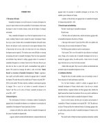
The overall study of grouting technology
Grouting is the process of bringing a mixture of grout (liquid or gas) into the slot on soil /
rock cracks or voids / empty aims to reduce the permeability to the extent necessary, or
strengthening the stability and strength of them, or both. Figure 1 shows the preliminary
drilling technology is mainly present
Figure 1. The kind of grouting technology is mainly present
The effect of drilling depends on the ability to penetrate the mortar grouting rock
environment. The research and practice have proved that pure pressure drilling technology
traditionally used cement ineffective in the sand, sand. In this case use ultra fine cement or
6
chemical grouting, drilling technology using high Jet pressure (JG) or osmotic drilling,
including drilling chemical grouting is a new problem for Vietnam .
1.5 The chemical grouting method
Chemical Grouting method is the active chemical solution injected into a layer of soil and
rock to improve the mechanical properties of it . Currently, chemical engineering drilling
fluid is used primarily glass. Liquid glass and chemical neutralization can be flashed
separately (also known as two- way solution ), or mixed together before grouting (a method
of solution). When flashed separately , they can be flashed simultaneously or in sequence .
To increase the durability of mortar over time , we now drilling chemicals used in
conjunction with cement. However, doing so requires more complex equipment and the
selection of grouting mortar aggregate ratio becomes much more complicated. The main
applications of chemical grouting include: (1) Prevent, cut-off seepage, flow in soil ,
rocks;(2) Increase the bearing capacity of soil , rock ; (3) Repairing defects works.
The chemical grouting method can effectively prevent the penetration of land lines, even
when there is flow. So choose the chemical grouting method thesis combines cement to
study in chapter 4 for the purpose of handling emergency erosion phenomenon underground
culverts under the dike and dike.
Concluction chapter 1
1. The system dykes located in Ha Nam Province is difficultly geological conditions,
usually annually occur sand boil, piping, even cause serious problems.
2. Research stabilize the dike seepage was more domestic and foreign authors concerned.
However, due to the complex nature of the geology dike red river delta to the research work
in the country are limiting the scope of research in a specific geographic area.
3. The solution treatment dike stable is many methods, from traditional ways to the new
solution proposed recently. Due to the complexity of the proof environment so each solution
has its limitations, even after the solution was negative earlier proposed solutions. To say
that that the proposed solutions to suit each specific conditions in accordance with the
recommended structure still needs to be further studied.
4. From the fact that the flood prevention work of the author himself, the existing
technology in Vietnam do not meet the requirements of troubleshooting permeability dike
foundations in emergency conditions. Research chemical grouting technology combined
cement chemicals to handle emergency effervescent extrusion phenomenon of flooding is
also necessary issues in the prevention of floods in Ha Nam in particular, for the whole
country in general.
7
CHAPTER 2
CLASSIFICATION OF HA NAM’ DIKE FOUNDATIONS BY STABLE
PERMEABILITY WIEWPOINT
2.1 The Natural features dyke Ha Nam Province
Nhue dike
Hong dike
Day dike
2.2 Classification of Ha Nam’dike foundation by To Xuan Vu’ wiewpoint
The classification criteria soil is mainly based on the composition and origin of the
sediments formed to provide names for each different soil types. It is not separate standards
for soil classification in accordance with the purpose of assessing the dike seepage stability.
In 2002, Vu Xuan authors of doctoral dissertation research entitled "Assessing the impact
absorption properties of some deformed sediments to stabilize the dike (for example a Red
River dyke)" [15] made approach towards classification of "the structure foundation". The
sensitivity of absorption depends on the presence of small particles of sand layer (Thai binh
type), the thickness of the thin impervious top stratum system of Vinh Phuc foundation,
distance from the river dike.
It has including the following type construct:
- The type soil are very sensitive with seepage deformation: I
1
;
- The type soil are sensitive with seepage deformation: I
2
, I
2a
; I
3
; II; III
1
;
- The type soil are less sensitive with seepage deformation: I
2c
; I
3
; I
4
; III
2
;
- The type soil are sustainably with seepage deformation: III
3
;
Under such an approach, the thesis was to collect geological survey documents of the dikes
in the province of Ha Nam, the segment had no material additional surveys. As a result, the
thesis has built map geological structures across the dike Ha Nam province presented in
Appendix 11 of the thesis.
From the geological structure map can also point out some key paragraphs (sensitive
permeable sand layer in which small particles are shallow, near the river dyke (Zt <3m and
the distance from the river dike S <500m ).
2.3 General remarks on the geological dykes Ha Nam Province
After analyzing geological data collected and the recommended additional survey, the thesis
reviews the geological structure of dykes in Ha Nam province as follows :
8
- Body dike embankment is more cohesive, derived from alluvial layer coated on the
surface, the coefficient permeability k ~ 10
-6
÷ 10
-8
cm/s;
- Next layer is coated on the surface sediments have variable thickness, usually from 1 to
8m, with weak performance waterproof, coefficient permeability k ~ 10
-5
÷ 10
-7
cm/s;
- The bottom layer of the coating is waterproof up sediment (coarse sand, fine sand, sand,
), permeability coefficient is usually k ~ 10
-4
÷ 10
-6
cm/s; aquiter layer thickness from a
few meters to tens of meters (with the drilling of up to 40m are still not finished).
- End of layer waterproof layer of hard clay or bedrock, often referred to as a non-aqueous
layer.
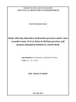
Simulation can simplify cross dike Ha Nam Province in 7 cases [24], as follows:
Figure 2. Simulation can simplify cross dike Ha Nam Province
With such a structure should the flood season, the river level will rise in the deep layer of
the aquifer, push upward pressure on the bottom of the impervious stratum. At the seat
cover with holes (wells, canals were dredged, ) water will exit. When water drains in the
area surrounding the seepage pressure under the coating will decrease, but the risk of
seepage flow will lead to the same fine particles escape, causing erosion and piping.
2.4 Safety reviews some focus dyke in Ha Nam province’dike
Because soil structure of dikes has not reflected in the hydraulic factor (Head water,
gradient permeability) and have not quantified the safety of permeability. So, in this chapter
thesis has simplified simulation dyke sections in the standard way as described in the U.S.
[24], then calculating safe levels steady seepage with water level alarm in the I, II, III.
Geological map of the soil structure, including 3 positions:
- Hong dike: Km133+00 to Km133+400
- Day dike: Km103+00 to Km103+570
- Nhue dike: Km3+280 to Km4+250
The thesis has made 3 model for this 3 positions with alarming levels I, II, III. Use of
mathematics formulas with simple diagram shown in Figure 2. The results are as follows:
9
Table 1. Data location and the water level of major dyke
Dikes Location Water level I (m) Water level II (m)
Water level III (m)
Riverside
Landside
R.d L.d R.d L.d
Hong
River
Type I
1a
: Km
133+0 ÷ Km
133+400
+5,2 +0,8 +5,5 +1,1 +7,1 + 2,2
Type I
1b
: Km
142+500 ÷ Km
144+100
+5,1 +1,2 +5,3 +1,2 +7,0 + 2,5
Day
River
Type I
1a
: Km
103+0 ÷ Km
103+500
+3,6 -1,5 +3,8 +0,8 + 4,2 + 0,8
Type I
2a
:
Km129+400 ÷
Km133+00
+ 2,7 +0,85 +3,1 +0,9 + 3,9 + 1,1
Nhue
River
Km 3+280 ÷
Km 4+250
+2,9 +1,2 +3,2 +1,3 +4,0 +1,8
(Sources:Department for Flood and Storm Dyke Management Ha Nam)
Table 2. Input data for calculating effective length uptream nature blanket X
3
, Pressure head
under impervious stratum at landside H
av
, Gradient of major dykes
Type Water
level
Unit Hong river Day river Nhue
river
Nature lever (
∇
MĐTN
)
0,5 0,0 -1,5 -1,5 0,0
Total Head H
BĐ I (m) 4,7 5,1 5,1 4,2 2,9
BĐ II (m) - - - - 3,2
BĐ III (m) - - - - 4
Head at check position
h
ao
BĐ I (m) 0,8 1,2 1,5 0,85 1,2
BĐ II (m) - - - - 1,3
BĐ III (m) - - - - 1,8
Soil type I1a I1b I1 I2a I1
Thickness of blanket Z
t
(m) 1,5 2,5 2 4 2,7
Cofficent permiability
blanket K
b
(m/s) 5.10
-7
5.10
-7
1.10
-8
10
-8
5.10
-7
Thickness of aquifer D
(m) 55 53 40 40 45
Cofficent permiability
of aquifer K
(m/s) 10
-4
10
-4
4.10
-5
4.10
-5
5.10
-5
Effective length from
riverside to check X (*)
(m) 93 89 140 141 79
Length from riverside
to landside toe S
(m) 43 39,47 90 91 29
Note:
- All problems are considered in the pond edge conditions from the toe 50 (m). Because the survey data in
Ha Nam Province, the distance from the downstream toe to the edge of the pond 50 ÷ 100 (m).
- Total Head at uptream H = ∇MNTL- ∇MĐTN
- At the position of the Day river from Km 103 +0 to Km 103 +500 nature lever landside is high ∇ 0.0 (m).
Section downstream of the pond have been carried out in Chapter III calculations
10
The safety of head beneath top impervious stratum of major dyke on Hong, Day, Nhue River
presented in Table 3.
Table 3. Calculating results of effective length uptream nature blanket X
3
, Pressure head
under impervious stratum at landside H
av
, Gradient of major dykes
Type Position X
3
(m)
H
av
(m) h
a
(m)
I
max
I
gh
Unsafe
Sand
boil
Piping
Water lever I
Hong
river
Type I
1a
: Km
133+0 ÷ Km
133+400
129 2,15 0,9 0,94 0,9 * *
Type I
1b
: Km
142+500 ÷
Km 144+100
162,7 2,85 1,2 0,77 0,9 *
Day
river
Type I
1a
: Km
103+0 ÷ Km
103+500
544 3,97 1,2 1,13 0,9 ** **
Type I
2a
:
Km129+400 ÷
Km133+00
769 3,7 2,4 0,726 0,9 *
Nhue
river
Km 3+280 ÷
Km 4+250
110,2 1,254 1,62 0,32 0,9
Water lever II
Nhue
river
Km 3+280 ÷
Km 4+250
110,23 1,384 1,62 0,346 0,9
Water lever III
Nhue
river
Km 3+280 ÷
Km 4+250
110,227 1,73 1,62 0,384 0,9 *
Note:
* The risk of unsafety
** The risk of serious insecurity
X
3
: effective length uptream nature blanket (m); H
av
: Pressure head under impervious stratum at landside
(m); h
a
: Limit pressure head under impervious stratum at landside (m) (m); I
max
: maximun calculate gradient
; I
gh
: Limit gradient.
From the results calculated by analytical formulas, commented:
- For Hong’dike and Day’dike, the water level at an alarming I was going to risk pushing
unsafe podium. The risk of erosion occurs for type I
1a
of the Hong river and the Day river.
- For Nhue’dike, only when the water level III is make unsafety to push the stratum (sand
boil)
2.5 Concluction chapter 2
- The stability of the dykes permeability depends on many factors: topography, geology,
hydrology, look at the position.
11
- Classification of the geological of dike by the authors precedes relatively meticulous and
demanding fully documentation to complete.
- For the dike of location Ha Nam province, the stability of permeability only depends on
effective length from dike to river and thickess of landside impevious stratum.
- Simulation can simplify cross dike Ha Nam Province in figure 2 and using the analytical
formulas to calculate the stability permiability for the dyke near the river. Calculation
results show that:
+ The Hong’ dike (Km133 to Km133 +400 +00) at risk of unsafety when water levels at an
alarming rate I.
+ The Day’dike (Km103+00 to Km103+500) at risk of unsafety whent water level at an
alarming rate II.
+ The Nhue’dike (Km3+280 to Km4+250) at risk of unsafety whent water level at an
alarming rate III.
The caculating results accordance with manage the actual management of flood prevention
in the province of Ha Nam. The position of the dyke major specified on the enclosed map.
12
CHAPTER 3
SOLUTION OF STABILITY PERMEABILITY FOR MAYJOR TA DAY’DIKE
3.1 The problem of stabilizing the dike seepage
Caculating seepage problems with analytical methods
- Theory:
+ The seepage is flow Darcy law;
+ Well penetration aquifer (perfect wells);
- Schematic diagram:
Figure 3. Model pressure head under imperious tratum
Effective length uptream nature blanket X
3
:
DZ
K
K
X
t
b
3
=
Therein: H – Total head (m); Z
t
– Thickness of imperious tratum (m); D - Thickness of
aquifer (m); K
b
– Cofficent permeability of imperious tratum (cm/s); K - Cofficent
permeability of aquifer (cm/s).
Pressure head under impervious stratum at landside H
av
:
t
s
gh
a
3
3
av
Z
F
I
h
XS
XXS
HH =<
+
−+
=
Therein:
S – Distance from river to toe landside dike (m);
X – Distance from river to pond of position check (m);
h
a
- Limit pressure head under impervious stratum at landside;
Z
t
- Thickness of imperious tratum;
F
s
– Safety factor, by 1,5 other caculating formula below:
t
s
gh
a
aw
t
t
a
w
gh
0
s
Z
F
I
h
h
Z'
Z
h
'
I
I
F =⇒
γ
γ
=
γ
γ
==
13
Therein: I
o
– Limit gradient pressure, the ratio of the specific gravity of the soil with a
specific gravity of water;
Accoding Bui Van Truong author study [13], I
gh
below:
I
gh
= 0,476 ~ 0,433 (small sand)
I
gh
= 0,510 ~ 0, 453 (fine sand)
Conditions safety sand boil:
I
cgh
= 0, 735 ~ 0,742 (small sand)
I
cgh
= 0, 720 ~ 0,709 (fine sand)
Caculating seepage problems by FEM Method
Using Seep/w software of GEO - Slope International Company - Canada. The water level in
the river is taken by the highest water levels occurred in history (1971), the downstream
water level is the water level in the pond (or wells), respectively. Exempted limited take
from the river edge to 328m from the toe, is divided into triangular elements and
quadrilateral, linked together by intermediate nodes. The model results in the following
form:
MN -1.5 (m)
Ao
7.5
-1
0.5
1
1.5
2
2.5
Figure 4. Calculation results of water pressure present case
3.2 Assess the stability permeability Ta Day dike
Location study
Location Research the area Km103÷Km103+200. Thesis choose this location to conduct
research because this is the most important position on the entire dike system Ha Nam
Province. In this area, the right is River, a river with an average elevation -2.0 m. On the
banks of the rice fields, with an average elevation +2.7m ÷ +3.0 m. Recommended with an
average elevation +7.0 ÷ +7.5 m. Pond aquaculture is an area of 7.000m
2
. Lowest elevation
-2.0 m pond.
Geology of dykes in the study area consists of 4 layers. Top soil is n
o
1, is colored brownish
clay, hard plastic state to semi-hard, with a thickness of 5.3 m ÷ 5. Next, layer 2 (cover
layer) is the layer of gray-brown clay soft plastic state, 0.5 ÷ 2.1 m thick. Next, layer 3, is
14
the gray clay layer recording, flowing gray plastic state, 1 ÷ 8m thick. Layer 4, the gray sand
granules have tight status register, this layer thickness of about 40 ÷ 50m
Combination water level used to calculate:
- Combination 1, Water level I: Riverside: +3,6(m); Landside: -1,5(m).
- Combination 2, Water lever III: Riverside: + 4,2(m); landside: +0,8(m).
The case of caculating
Case 1: Assessing the dike current state, the calculated water level combined with alarming I.
Case 2: The problem of treat safety permeability, proposed three options: (1) Fill the pond,
(2) Build relief wells, and (3) Build wells by soil cement. Calculate the water level
combined with an alarming rate III. When calculated by FEM method, pressure relief wells
are simulated free water column, permeability k= 3,0 x10
-4
(m/s); Coefficient permeability
of soil cemnet K
tuong
= 3,16 x10
-7
(m/s).
Table 4. Caculation results for case 1
Unit: m
Water
lever
river
side
Water
level
land
side
Analytical methods FEM methos
H
av
I
max
H
av
I
max
+3,6 -1,5 3,467 1,387 3,477 1,39
Comment: The results calculated by analytical formulas and FEM model shows, at position
pond is risk boil sand, piping when water levels up to alarm I. Compared phenomena occur
in practice, the calculation results in relatively consistent.
Conclusion: There should be solution to stabilize the dike seepage.
3.3 Proposed solutions to improve the stability of the Ta day dyke
Solution fill the pond landside
Filling the pond to +0,8 (m), lower than the downstream berm.
Results from analytical methods larger than FEM methods, below:
Water
level
river
side
Water
level
land
side
Analytical methods FEM methos
H
av
(m) I
max
H
av
(m) I
max
+4,2 +0,8 2,74 0,57 2,425 0,5
Conclusion: Ensure that the dike safety permeability when filling pond to +0,8 (m)
Solutions of system pressure relief wells
- Relief wells are arranged as shown in Figure 5.
15
Figure 5. Treatment plan layout system relief wells
- Value H
av
and I
max
from Analytical methods larger than FEM methods:
Water level
river side
Water level
land side
Analytical methods FEM methos
H
av
(m) I
max
H
av
(m) I
max
+4,2 +0,8 0,87 0,48 0,6 0,45
Conclusion: The result shows that, as relief wells distance 10m, 20m depth the phenomenon
prevented podium pond. However, conditions at a later time if the user does not flush well,
the efficiency of the wells down, down to the level of 50% is not safe anymore. Therefore,
the thesis proposed solution stabilize the wells by overlap soil cement to replace relief wells
to overcome this drawback.
Solusion well by overlap soil cement
- Well by overlap soil cement are arranged as shown in Figure 6. Where: P - depth wells, h
g
- height of wells from nature ground.
Figure 6. Treatment plan layout wells by overlap soil cemnet
Value H
g
from Analytical methods larger than FEM methods,
h
g
(m)
Analytical methods FEM methos
1,5 2,0 2,5 3,0 1,5 2,0 2,5 3,0
P = 10m 1,466 1,25 1,09 0,977 1,4 1,25 1,05 1,0
P = 20m 1,41 1,21 1,06 0,944 1,3 1,1 1,0 0,9
P = 30m 1,37 1,17 1,02 0,914 1,2 1,05 0,93 0,85
Conclusion: Only depth wells P=10 (m) and height of wells from nature ground h
g
=1,5 (m)
is safety permeability.
H
1
K
K
16
3.4 Assess the economic efficiency
Funding schemes are calculated on the prices same time, the unit price as of June 2013.
Schemes Fill pond Relief wells Wells by overlap soil cemnet
Funding (VND) 5.087.546.400 9.800.000.000 5.064.000.000
Conclusion: The plan to reduce pressure wells have the highest prices, plans fin piles wells
and ponds downstream embankment schemes have approximately the same price. However,
plans for wells enclosure poles has several advantages over: the land transportation
environment pollution, social still aquaculture, transformation is not produced, no loss of
arable land.
3.5 Concluction chapter 3
1.Treatment stability permeability for some major dyke is a urgent requirement in practice
in the province of Ha Nam. In this chapter, thesis has selected one section dyke from
Km103 ÷ Km103+200 to check seepage deformation. This dyke exist landside
fisheries’pond, annually on the first alarm (upper water level +3.6) sand boil and piping
appearance. Calculation results show that checks the status at the first alarm occurs due to
piping. The plan was laid out filled pond, however not accepted.
2. Dissertation proposal and calculate 3 treatment options:
- Fill pond to + 0,8;
- Build system pressure relief wells at the landside toe;
- Create wells by overlap soil cement.
All 3 options are calculated with the water level alarm level III (the upstream water level
+4.2), ensuring the conditions causing cracks in underground erosion phenomenon pond.
3. Calculating the head pressure of the dike can be calculated by the theory, based on the
analytical formulas or calculated by FEM method based on commercial software.
Theoretical results calculated in favor of safety. However, the basic design steps using the
formula described in the thesis is acceptable.
4. Through analysis and selection, the authors propose 3 options to apply for the
recommended treatment taught with the following parameters:
- Depth wells P=10 (m) and height of wells from nature ground h
g
=1,5 (m), wells along the
perimeter of the pond, the entire circumference of about 600m.
- Wells was create by overlap soil cement column and construction by Jet-grouting
technology, presented chapter 4.
- High wellhead to + 0.8, or downstream berm.
5. With the same major dike can be used this methos for caculating and design.
17
CHAPTER 4
STUDY EXPERIMENTAL CHEMICAL GROUTING FOR THE EMERGENCY
TREATMENT THE DIKE SEEPAGE PROBLEMS
4.1 The purpose and studied methods
- Research purpose: study about ability to apply chemicals grouting for emergency
treatment the dike seepage problems.
- The studied methods: combined theoretical and experimental study in labory.
4.2 Practiced methods
Location conducting the test is clearing the landside, next to the Moc Nam’ sluice, Duy Tien
district, Ha Nam province at Km 123 +050 m on the Huu Hong dike system.
Geology
Results drilling geological surveys at the filed showed a soft clay layer (layer 3), about 3,7
m thick plastic, from -4,30 ÷ -8,00 m elevation. Below this layer is the layer of plastic
flowing sand, fine-grained (class 4) of a thickness exceeding 40 m.
Piles testing
Study the difference between merely drilling chemicals and drilling chemicals to combine
cement, construction thesis in the field 3 of 7 stakes experiments, in which the two column
A1, A2 constructed by method of JG, pile construction method A3 drilling low pressure.
Aggregate grout piles used for 1m
3
following:
Column
Cement Glass water H
2
SO
4
(70%) NaHCO
3
A1 750 kg - - -
A2 750 kg 60 L - -
A3 200 kg 60 L 15 L 6 kg
Figure 7. Schematic piles testing
The field testing
Experiments conducted in the borehole water poured piles and compared with experimental
results in the natural soil, untreated.
18
4.3 Study laboratory experiments
The same times with piles tested in the field, the team has conducted laboratory model
casting
The steps conducted model casting
- Mix cement with water in a 1:1 weight ratio;
- Mix with 380ml water 800g of cement sand mortar into fine;
- Dilute with water glass liquid volume ratio 1:4;
- Pour slowly the entire amount of cement paste made in step 2 into the sample tube (for
chemical form: Filling glass with 100ml water dilution), just pour stir just until the initial
setting mortar.
The experimental work
Thí nghiệm nén nở hông được tiến hành trên tất cả các mẫu hiện trường và mẫu đúc trong
phòng bằng máy nén TYA-300C theo TCVN 3118.
Thí nghiệm hệ số thấm đất nền trước và sau khi xử lý bằng phương pháp đổ nước hố khoan.
Unconfined compression tests were conducted on all samples in the field and form molded
by the compressor room TYA-300C according ISO 3118.
Testing the permeability coefficient before and after treatment by means of pouring water
boreholes.
4.4 The study results
- Compressive strength of field samples after 28 days:
Name Type samples
Unconfined (kG/cm
2
)
A1
UC1 1,697
M1 123,7
A2
UC2 0,867
M2 121,0
- Compressive strength of labory sample:
Material curing time (day) Compressive strength (kG/cm
2
)
Cement
1 10,9
3 20,1
7 37,7
Cement-
Chemical
1 4,0
3 11,2
7 13,8
- Cofficient permeability nature soil (untreated): K = 4,079x10
-4
(cm/s).
- Cofficient permeability soil after treating: K = 3,16 x 10
-5
(cm/s).
19
4.5 Comment results
The phenomenon of rapid adhesive chemicals being put into the mortar grouting was
confirmed through observation during the test piles in the field and in the preparation of
samples being.
The results of field experiments on samples and prototypes are being shown, the treatment
soil by using JG methos has a significant effect on the ability to increase compressive
strength of the soil.
Use of cement - chemical effectively improved waterproofing for the large coefficient
permeability, while ensuring long-term durability, can be applied to the dike seepage
treatment in emergency situations.
4.6 Conclusions chapter 4
- Time gelatinized mixture of soil - cement depending on the mix of chemicals, can change
between 3 to 30 seconds. Compared with the setting time of cement - construction land
under high pressure drilling methods, the setting time of cement - soil - chemical accelerate.
- Using cement-chemical mortar to mortar grouting can improve the strength of markedly.
Improve the level of intensity depending on the characteristics of the land. For example, for
many soil sand content, increasing the efficiency of high intensity will be more than soil
clay content.
- Mortar XM-HC is pumped into the pressure grouting method capable of improving the
permeability coefficient significantly.
20
CONCLUSION AND RECOMENDATION
1. Conclusion
1.According to the classification recommended by previous authors, the thesis was to collect
geological survey data and additional survey, conducted sorts the dykes, classification
mapping should be left to the dikes in Ha Nam province.
Through the analysis of the geological structure of dykes, compared calculate seepage
pressure thesis concludes can simulate simplified geological section dykes Ha Nam
province as Figure 2 and using analytical formulas to calculate stability proof test in step up
investment projects.
The thesis has shown a quantitative proof of the level of safety for key stage 3, which is: (1)
Huu Hong dikes: Km117+900 ÷ Km118+600; Km119+400 ÷ Km119+800; (2) Ta Day
dikes: K101 + 270 ÷ Km 102 + 130 và Km 103 + 00 ÷ Km 103 + 200; (3) Nhue dikes: K3
+ 280 ÷ K4 + 250. The results calculated in accordance with the actual situation.
2.Thesis calculate permeability test for stability dyke’ Ta day (Km103 to Km103 +200) and
capable boil sand when the water level alarming II. The thesis proposed three options: (1)
Fill the pond, (2) Build system pressure relief wells, (3) Create wells by overlap soil cement.
All 3 options are safe when the river water level alarm level III. Dissertation proposal fins
used as well as stakes in accordance with specific conditions and local sustainability.
3. Thesis research conducted test chemical grouting technology combined cement and the
following conclusions:
- Using chemical glass of water mixed with cement can shorten the time of the gelatinized
mixture between 10 ÷ 30 seconds, so can be used to treatment the flow’soil conditions.
- Using aggregate mortar XM/HC at a rate of 750 kg HC XM/60 liters (water glass) for
handling emergency incidents underground erosion.
- The experimental study of the thesis is just the first step results in a specific project. Due
to time and budget should not conditional thesis to research deeper and wider issues.
2. Recomendation
- Propound Ha Nam province using maps classification results in the dike thesis. Strengthen
the management of dykes and flood control plans for major dyke
- In order to evade the need to build a system of wells reduced pressure, and the process
must have regular maintenance in order to avoid the filter rule. The piece has many lakes
21
and ponds adjacent to the toe (Km103 ÷ Km103+200 Ta Day dikes) to build wells was
create by overlap soil cement column and construction by Jet-grouting technology.
-Propose to use the results of thesis research on the development of common technical
manuals in the design, maintenance and emergency incident handling the dike seepage
- It should continue to research the technology drilling chemicals, advanced to build the
standard /technical guidance.
3. Thesis development
- Due to time and funding to build the geological zoning map by the sensitivity of
permeability is not sufficient on all dikes. This study should be continued.
-The experimental study of chemical grouting technology is just the first step. There is a
need to continue research and development to improve the technology, both in terms of
materials and construction technologies. Specifically:
+ The scope of application: Extending the scope of application for the gravel, large rocks
cracked, especially in the position of groundwater flow. In addition to waterproof the dike
can also apply for research purposes and other types of work such as wall of lazzen,
underground waterproofing
+ The study material: Need to continue to further study the material properties cement-
chemical. Especially the influence of the environmental factors of the ground (physics,
chemistry), mixing ratio gelatinized to speed, the coefficient of permeability, durability,
hardness of the material
+ The technology and testing methods, quality control: Need further research and
development of detection technology and seepage detected position to assess the quality of
the work after treatment permeability.
22
PUBLICATIONS OF THE AUTHOR
1. Nguyen Quoc Đat (2012), Experience improve stability and treatment of the river dike
seepage, The journal of Science and Technology of Water Resources Institute,
November, Ha Noi.
2. Nguyen Quoc Đat (2011), Results of studies geological classify the Ha Nam province
dike safety base on standpoint stable permeability, The journal of Science and
Technology of Water Resources Institute N
o
05+06 December, Ha Noi.
3. Nguyen Quoc Dung, Nguyen Quoc Đat (2011), The chemical grouting technology for
waterproofing and application capabilities in Vietnam, The journal of structural
building technology, Ha Noi.
4. Phung Vinh An, Nguyen Quoc Đat (2005), Some problems about the column soil cement
for stabilized pits, The Journal of Agriculture and Rural Development ISN 0866 –
7020, Ha Noi.