Chapter3: Modules and Hierarchical structure pps
Bạn đang xem bản rút gọn của tài liệu. Xem và tải ngay bản đầy đủ của tài liệu tại đây (610.3 KB, 24 trang )
1
NATIONAL UNIVERSITY OF HO CHI MINH CITY
UNIVERSITY OF INFORMATION TECHNOLOGY
FACULTY OF COMPUTER ENGINEERING
LECTURE
Lecturer: Lam Duc Khai
VERILOG
Hardware Description Language
Chapter3: Modules and
Hierarchical structure
Subject:
2
Agenda
1. Chapter 1: Introduction ( Week1)
2. Chapter 2: Fundamental concepts (Week1)
3. Chapter 3: Modules and hierarchical structure (Week2)
4. Chapter 4: Primitive Gates – Switches – User defined
primitives (Week2)
5. Chapter 5: Structural model (Week3)
6. Chapter 6: Behavioral model – Combination circuit (Week4)
7. Chapter 7: Behavioral model – Sequential circuit (Week5)
8. Chapter 8: Tasks and Functions (Week6)
9. Chapter 9: State machines (Week6)
10. Chaper 10: Testbench and verification (Week7)
3
Agenda
Hierarchical structure
Modules
Instances
3. Chapter 3: Module and Hierarchical structure
4
Hierarchical structure
• The Verilog HDL supports a hierarchical hardware description
structure by allowing modules to be embedded within other
modules. Higher level modules create instances of lower level
modules and communicate with them through input, output,
and bidirectional ports. These module input/output (I/O) ports
can be scalar or vector.
5
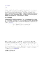
Top-down design methodology
Top-level block
identify
enough
to build
Cannot further be divided
Hierarchical structure (Cont’d)
6
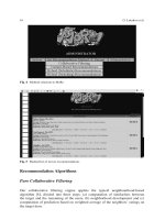
Bottom-up design methodology
Top-level block, the
final block in design
Building blocks that are
available is identified
build
Hierarchical structure (Cont’d)
7
Design Methodologies
• A combination of top-down and bottom-up flows is typically
used
– Design architects define the specifications of the top-level
block
– Logic designers break up the functionality into blocks and
sub-blocks.
– At the same time, circuit designers are designing optimized
circuits for leaf-level cells. They build higher-level cells by
using these leaf cells.
– The flow meets at an intermediate point
Hierarchical structure (Cont’d)
8
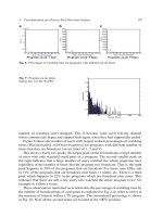
Example: 4-bit Ripple Carry Counter
Ripple Carry Counter T-flipflop
Design Hierarchy
Hierarchical structure (Cont’d)
9
Modules
• A module is the basic building block in Verilog
– Can be an element or a collection of lower-level design
blocks
– Provide functionality for higher-level block through its
port interface
– Hide internal implementation
– Is used at many places in the design
– Allows designers modify module internals without
effecting the rest of design
10
Typical Module Components Diagram
Module name, Port list (optional, if there are ports)
Port declarations
Parameter list
Declaration of variables (wires, reg, integer etc.)
Instantiation of inner (lower-level) modules
Structural statements (i.e., assign and gates)
Procedural blocks (i.e., always and initial blocks)
Tasks and functions
endmodule declaration
Modules (Cont’d)
11
Example: 4-bit Ripple Carry Counter
Ripple Carry Counter T-flipflop
Design Hierarchy
Module
Module
Module
Modules (Cont’d)
12
Module description
module module name ( port name, port name,…);
module_port declaration
data type declaration
logic description part
endmodule
A module definition
A part of a chip, or
whole the chip
module
The file name for RTL source must be
“module name.v”
Modules (Cont’d)
13
module module name ( port name, port name,…);
module_port declaration
Declare whether the ports are input and/or output
input <port_size> port name, port name, …;
output <port_size> port name, port name, …;
inout <port_size> port name, port name, …;
A part of a chip,
or whole the
chip
module
ports
4
8
1
1
16
4
4
module data_conv ( a, b, …);
input [3:0] a;
input [7:0] b;
output [3:0] e, f;
output [15:0] g;
inout c, d;
a
b
c
d
g
f
e
Modules (Cont’d)
Module_port declaration
14
reg or wire
Port Rules Diagram
input
output
wirereg or wire
wire
inoutwire
wire
EXTERNAL
MODULE
Internal ports
INTERNAL
MODULE
Outside connectors
to internal ports, i.e.,
variables corresponding
to ports in instantiation
of internal module
Example:
module external
reg a;
wire b;
internal in(a, b); //instantiation
…
endmodule
module internal(x, y)
input x;
output y;
wire x;
reg y;
…
endmodule
port-connector
General rule (with few exceptions) Ports in all modules except for the
stimulus module should be wire. Stimulus module has registers to set data
for internal modules and wire ports only to read data from internal modules.
Modules (Cont’d)
15
module module name ( port name, port name,…);
module_port declaration
Data type declaration
Declare characteristics of variables
wire <size> variable name, variable name, …;
wire <size> variable name, variable name, …;
module
4
8
1
1
16
4
4
wire [3:0] a;
wire [7:0] b;
wire c, d;
wire [3:0] f;
wire [7:0] q1, q2, q3, q4;
wire sel3, …;
….
a
b
c
d
g
f
e
for net data type
SEL
q2
q1
sel3
q3
Modules (Cont’d)
Data type declaration
16
module module name ( port name, port name,…);
module_port declaration
Data type declaration
Define signals which are output of FF, registers, and
other memory elements as register type variable.
reg <size> variable name, variable name, …;
reg <size> variable name, variable name, …;
wire [3:0] e;
wire [15:0] g;
wire q2;
….
for register data type
module
4
8
1
1
16
4
4
a
b
c
d
g
f
e
q2
Output does not have to be declared as register data type
Input (inout) must not be declared as register data type
Note:
Modules (Cont’d)
Data type declaration (Cont’d)
17
Example: Mistakes and correct on register and net data type
module1
module2
reg
reg
reg
reg
wire
wire
wire
reg
wire
reg
wire
wire
reg
module2_1
wire
reg
reg
wire wire
The output of memory element
must be defined as reg
They must be defined as wire at
these points.
: memory element
Modules (Cont’d)
18
module2
reg
wire
reg
module2_1
wire
reg
reg
reg
wire
module1
reg
reg
wire
reg
wire
wire
reg
wire
reg
wire
wire
wire
wire
reg
wire
wire
wire
wire
reg
wire
Suppose this part is programmed by
using always statement.
Assume gates are not defined by using
always nor function statements
Modules (Cont’d)
Example: Mistakes and correct on register and net data type (Cont’d)
19
module2
reg
wire
reg
module2_1
wire
reg
reg
reg
wire
module1
reg
reg
wire
reg
wire
wire
reg
wire
reg
wire
wire
wire
wire
reg
wire
wire
wire
wire
reg
wire
Suppose this part is programmed by
using always statement.
Note: reg data type cannot be declared as an input !!!
wire wire
reg
wire wire
wire
wire
wire
reg
reg
reg
Explain later
Example: Mistakes and correct on register and net data type (Cont’d)
Modules (Cont’d)
20
module module name ( port name, port name,…);
module_port declaration
Data type declaration
Logic description part
endmodule
The main part of logic is
written here.
Logic is coded in this part using various
operator including connections to lower level
blocks.
module
4
8
1
1
16
4
4
a
b
c
d
g
f
e
Modules (Cont’d)
Logic description part (Cont’d)
21
Example: 4-bit Ripple Carry Counter
Ripple Carry Counter
module
T-flipflop module
Instances
Module
Instance1
T_FF
Module
Instance2
T_FF
Instance3
T_FF
Instance4
T_FF
Instance1
D_FF
Instance1
Inverter
22
Instances (Cont’d)
Connecting module instance ports by ordered list
module topmod;
wire [4:0] v;
wire a,b,c,w;
modB b1 (v[0], v[3], w, v[4]);
endmodule
module modB (wa, wb, c, d);
inout wa, wb;
input c, d;
tranif1 g1 (wa, wb, cinvert);
not #(2, 6) n1 (cinvert, int);
and #(6, 5) g2 (int, c, d);
endmodule
The port expressions listed for the module instance shall be in the same order as the
ports listed in the module declaration.
23
Connecting module instance ports by name
Connections are made by name, the order in which they appear is irrelevant.
module topmod;
wire [4:0] v;
wire a,b,c,w;
modB b1 (.wb(v[3]),.wa(v[0]),.d(v[4]),.c(w));
endmodule
module modB(wa, wb, c, d);
inout wa, wb;
input c, d;
tranif1 g1(wa, wb, cinvert);
not #(6, 2) n1(cinvert, int);
and #(5, 6) g2(int, c, d);
endmodule
Instances (Cont’d)
24
END