Tài liệu Modules and Ports part 2 pptx
Bạn đang xem bản rút gọn của tài liệu. Xem và tải ngay bản đầy đủ của tài liệu tại đây (21.15 KB, 7 trang )
[ Team LiB ]
4.2 Ports
Ports provide the interface by which a module can communicate with its environment.
For example, the input/output pins of an IC chip are its ports. The environment can
interact with the module only through its ports. The internals of the module are not
visible to the environment. This provides a very powerful flexibility to the designer. The
internals of the module can be changed without affecting the environment as long as the
interface is not modified. Ports are also referred to as terminals.
4.2.1 List of Ports
A module definition contains an optional list of ports. If the module does not exchange
any signals with the environment, there are no ports in the list. Consider a 4-
bit full adder
that is instantiated inside a top-level module Top. The diagram for the input/output ports
is shown in Figure 4-3
.
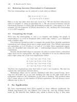
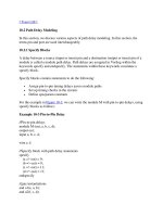
Figure 4-3. I/O Ports for Top and Full Adder
Notice that in the above figure, the module Top is a top-level module. The module
fulladd4 is instantiated below Top. The module fulladd4 takes input on ports a, b, and
c_in and produces an output on ports sum and c_out. Thus, module fulladd4 performs an
addition for its environment. The module Top is a top-level module in the simulation and
does not need to pass signals to or receive signals from the environment. Thus, it does not
have a list of ports. The module names and port lists for both module declarations in
Verilog are as shown in Example 4-2
.
Example 4-2 List of Ports
module fulladd4(sum, c_out, a, b, c_in); //Module with a list of ports
module Top; // No list of ports, top-level module in simulation
4.2.2 Port Declaration
All ports in the list of ports must be declared in the module. Ports can be declared as
follows:
Verilog Keyword Type of Port
input Input port
output Output port
inout Bidirectional port
Each port in the port list is defined as input, output, or inout, based on the direction of the
port signal. Thus, for the example of the fulladd4 in Example 4-2
, the port declarations
will be as shown in Example 4-3
.
Example 4-3 Port Declarations
module fulladd4(sum, c_out, a, b, c_in);
//Begin port declarations section
output[3:0] sum;
output c_cout;
input [3:0] a, b;
input c_in;
//End port declarations section
...
<module internals>
...
endmodule
Note that all port declarations are implicitly declared as wire in Verilog. Thus, if a port is
intended to be a wire, it is sufficient to declare it as output, input, or inout. Input or inout
ports are normally declared as wires. However, if output ports hold their value, they must
be declared as reg. For example, in the definition of DFF, in Example 2-5
, we wanted the
output q to retain its value until the next clock edge. The port declarations for DFF will
look as shown in Example 4-4
.
Example 4-4 Port Declarations for DFF
module DFF(q, d, clk, reset);
output q;
reg q; // Output port q holds value; therefore it is declared as reg.
input d, clk, reset;
...
...
endmodule
Ports of the type input and inout cannot be declared as reg because reg variables store
values and input ports should not store values but simply reflect the changes in the
external signals they are connected to.
Note that the module fulladd4 in Example 4-3 can be declared using an ANSI C style
syntax to specify the ports of that module. Each declared port provides the complete
information about the port. Example 4-5
shows this alternate syntax. This syntax avoids
the duplication of naming the ports in both the module definition statement and the
module port list definitions. If a port is declared but no data type is specified, then, under
specific circumstances, the signal will default to a wire data type.
Example 4-5 ANSI C Style Port Declaration Syntax
module fulladd4(output reg [3:0] sum,
output reg c_out,
input [3:0] a, b, //wire by default
input c_in); //wire by default
...
<module internals>
...
endmodule
4.2.3 Port Connection Rules
One can visualize a port as consisting of two units, one unit that is internal to the module
and another that is external to the module. The internal and external units are connected.
There are rules governing port connections when modules are instantiated within other
modules. The Verilog simulator complains if any port connection rules are violated.
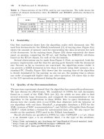
These rules are summarized in Figure 4-4
.
Figure 4-4. Port Connection Rules
Inputs
Internally, input ports must always be of the type net. Externally, the inputs can be
connected to a variable which is a reg or a net.
Outputs
Internally, outputs ports can be of the type reg or net. Externally, outputs must always be
connected to a net. They cannot be connected to a reg.
Inouts
Internally, inout ports must always be of the type net. Externally, inout ports must always
be connected to a net.
Width matching
It is legal to connect internal and external items of different sizes when making inter-
module port connections. However, a warning is typically issued that the widths do not
match.
Unconnected ports
Verilog allows ports to remain unconnected. For example, certain output ports might be
simply for debugging, and you might not be interested in connecting them to the external
signals. You can let a port remain unconnected by instantiating a module as shown
below.
fulladd4 fa0(SUM, , A, B, C_IN); // Output port c_out is unconnected
Example of illegal port connection
To illustrate port connection rules, assume that the module fulladd4 in Example 4-3
is
instantiated in the stimulus block Top. Example 4-6
shows an illegal port connection.
Example 4-6 Illegal Port Connection
module Top;
//Declare connection variables
reg [3:0]A,B;
reg C_IN;
reg [3:0] SUM;
wire C_OUT;
//Instantiate fulladd4, call it fa0
fulladd4 fa0(SUM, C_OUT, A, B, C_IN);
//Illegal connection because output port sum in module fulladd4
//is connected to a register variable SUM in module Top.
.
.
<stimulus>
.
.
endmodule
This problem is rectified if the variable SUM is declared as a net (wire).
4.2.4 Connecting Ports to External Signals
There are two methods of making connections between signals specified in the module
instantiation and the ports in a module definition. These two methods cannot be mixed.
These methods are discussed in the following sections.
Connecting by ordered list
Connecting by ordered list is the most intuitive method for most beginners. The signals to
be connected must appear in the module instantiation in the same order as the ports in the
port list in the module definition. Once again, consider the module fulladd4 defined in
Example 4-3
. To connect signals in module Top by ordered list, the Verilog code is
shown in Example 4-7
. Notice that the external signals SUM, C_OUT, A, B, and C_IN
appear in exactly the same order as the ports sum, c_out, a, b, and c_in in module