power distribution
Bạn đang xem bản rút gọn của tài liệu. Xem và tải ngay bản đầy đủ của tài liệu tại đây (23.53 MB, 576 trang )
Whitaker, Jerry C. “Power Distribution and Control”
AC Power Systems Handbook, 2
nd
Edition.
Jerry C. Whitaker
Boca Raton: CRC Press LLC, 1999
© 1999 CRC Press LLC
Chapter
1
Power Distribution and
Control
1.1 Introduction
Every electronic installation requires a steady supply of clean power to function
properly. Recent advances in technology have made the question of alternating cur-
rent (ac) power quality even more important, as microcomputers are integrated into
a wide variety of electronic products. The high-speed logic systems prevalent today
can garble or lose data because of power-supply disturbances or interruptions.
When the subject of power quality is discussed, the mistaken assumption is often
made that the topic only has to do with computers. At one time this may have been
true because data processing computers were among the first significant loads that
did not always operate reliably on the raw power received from the serving electri-
cal
utility. With the widespread implementation of control by microprocessor-based
single-board computers (or single-chip computers), however, there is a host of
equipment that now operates at voltage levels and clock speeds similar to that of the
desktop or mainframe computer. Equipment as diverse as electronic instrumenta-
tion, cash registers, scanners, motor drives, and television sets all depend upon
onboard computers to give them instructions. Thus, the quality of the power this
equipment receives is as important as that supplied to a data processing center. The
broader category, which covers all such equipment, including computers, is perhaps
best described as
sensitive electronic equipment
.
The heart of the problem that seems to have suddenly appeared is that while the
upper limit of circuit speed of modern digital devices is continuously being raised,
the logic voltages have simultaneously been reduced. Such a relationship is not acci-
dental. As more transistors and other devices are packed together onto the same sur-
face area, the spacing between them is necessarily reduced. This reduced distance
© 1999 CRC Press LLC
between components tends to lower the time the circuit requires to perform its
designed function. A reduction in the operating voltage level is a necessary—and
from the standpoint of overall performance, particularly heat dissipation, desir-
able—by-product of the shrinking integrated circuit (IC) architectures.
The ac power line into a facility is, of course, the lifeblood of any operation. It is
also, however, a frequent source of equipment malfunctions and component failures.
The utility company ac feed contains not only the 60 Hz power needed to run the
facility, but also a variety of voltage sags, surges, and transients. These abnormali-
ties cause different problems for different types of equipment.
1.1.1 Defining Terms
To explain the ac power-distribution system, and how to protect sensitive loads from
damage resulting from disturbances, it is necessary first to define key terms.
•
Active filter
. A switching power processor connected between the line and a non-
linear load, with the purpose of reducing the harmonic currents generated by the
load.
•
Alternator
. An ac generator.
•
Boost rectifier
. An unfiltered rectifier with a voltage-boosting dc/dc converter
between it and the load that shapes the line current to maintain low distortion.
•
Circular mil
. The unit of measurement for current-carrying conductors. One mil
is equal to 0.001 inches (0.025 millimeters). One circular mil is equal to a circle
whose diameter is 0.001 inches. The area of a circle with a 1-inch diameter is
1,000,000 circular mils.
•
Common-mode noise
. Unwanted signals in the form of voltages appearing
between the local ground reference and each of the power conductors, including
neutral and the equipment ground.
•
Cone of protection
(lightning). The space enclosed by a cone formed with its
apex at the highest point of a lightning rod or protecting tower, the diameter of
the base of the cone having a definite relationship to the height of the rod or
tower. When overhead ground wires are used, the space protected is referred to as
a
protected zone
.
•
Cosmic rays
. Charged particles (ions) emitted by all radiating bodies in space.
•
Coulomb
. A unit of electric charge. The coulomb is the quantity of electric
charge that passes the cross section of a conductor when the current is maintained
constant at one ampere.
•
Counter-electromotive force
. The effective electromotive force within a system
that opposes the passage of current in a specified direction.
© 1999 CRC Press LLC
•
Counterpoise
. A conductor or system of conductors arranged (typically) below
the surface of the earth and connected to the footings of a tower or pole to pro-
vide
grounding for the structure.
•
Demand meter
. A measuring device used to monitor the power demand of a sys-
tem; it compares the peak power of the system with the average power.
•
Dielectric
(ideal). An insulating material in which all of the energy required to
establish an electric field in the dielectric is recoverable when the field or
impressed voltage is removed. A perfect dielectric has zero conductivity, and all
absorption phenomena are absent. A complete vacuum is the only known perfect
dielectric.
•
Eddy currents
. The currents that are induced in the body of a conducting mass by
the time variations of magnetic flux.
•
Efficiency
(electric equipment). Output power divided by input power, expressed
as a percentage.
•
Electromagnetic compatibility
(EMC). The ability of a device, piece of equip-
ment, or system to function satisfactorily in its electromagnetic environment
without introducing intolerable electromagnetic disturbances.
•
Generator
. A machine that converts mechanical power into electrical power. (In
this publication, the terms “alternator” and “generator” will be used interchange-
ably.)
•
Grid stability
. The capacity of a power distribution grid to supply the loads at any
node with stable voltages; its opposite is
grid instability
, manifested by irregular
behavior of the grid voltages at some nodes.
•
Ground loop
. Sections of conductors shared by two different electronic and/or
electric circuits, usually referring to circuit return paths.
•
Horsepower
. The basic unit of mechanical power. One horsepower (hp) equals
550 foot-pounds per second or 746 watts.
•
HVAC
. Abbreviation for “heating, ventilation, and air conditioning” system.
•
Hysteresis loss
(magnetic, power, and distribution transformer). The energy loss
in magnetic material that results from an alternating magnetic field as the ele-
mentary magnets within the material seek to align themselves with the reversing
field.
•
Impedance
. A linear operator expressing the relationship between voltage and
current. The inverse of impedance is
admittance
.
•
Induced voltage
. A voltage produced around a closed path or circuit by a time
rate of change in a magnetic flux linking that path when there is no relative
motion between the path or circuit and the magnetic flux.
© 1999 CRC Press LLC
•
Joule
. A unit of energy equal to one watt-second.
•
Life safety system
. Systems designed to protect life and property, such as emer-
gency lighting, fire alarms, smoke exhaust and ventilating fans, and site security.
•
Lightning flash
. An electrostatic atmospheric discharge. The typical duration of a
lightning flash is approximately 0.5 seconds. A single flash is made up of various
discharge components, usually including three or four high-current pulses called
strokes
.
•
Metal-oxide varistor
. A solid-state voltage-clamping device used for transient
suppression applications.
•
Normal-mode noise
. Unwanted signals in the form of voltages appearing in line-
to-line and line-to-neutral signals.
•
Permeability
. A general term used to express relationships between magnetic
induction and magnetizing force. These relationships are either: (1)
absolute per-
meability
, which is the quotient of a change in magnetic induction divided by the
corresponding change in magnetizing force; or (2)
specific
(relative)
permeabil-
ity
, which is the ratio of absolute permeability to the magnetic constant.
•
Point of common coupling
(PCC). The point at which the utility and the con-
sumer’s power systems are connected (usually where the energy meter is
located).
•
Power fa ctor
. The ratio of total watts to the total rms (root-mean-square) volt-
amperes in a given circuit. Power factor =
W
/
VA
.
•
Power quality
. The degree to which the utility voltage approaches the ideal case
of a stable, uninterrupted, zero-distortion, and disturbance-free source.
•
Radio frequency interference
. Noise resulting from the interception of transmit-
ted radio frequency energy.
•
Reactance
. The imaginary part of impedance.
•
Reactive power
. The quantity of “unused” power that is developed by reactive
components (inductive or capacitive) in an ac circuit or system.
•
Safe operating area
. A semiconductor device parameter, usually provided in
chart
form, that outlines the maximum permissible limits of operation.
•
Saturation
(in a transformer). The maximum intrinsic value of induction possible
in a material.
•
Self-inductance
. The property of an electric circuit whereby a change of current
induces an electromotive force in that circuit.
•
Single-phasing
. A fault condition in which one of the three legs in a three-phase
power system becomes disconnected, usually because of an open fuse or fault
condition.
© 1999 CRC Press LLC
•
Solar wind
. Charged particles from the sun that continuously bombard the sur-
face of the earth.
•
Switching power supply
. Any type of ac/ac, ac/dc, dc/ac, or dc/dc power con-
verter
using periodically operated switching elements. Energy-storage devices
(capacitors and inductors) are usually included in such supplies.
•
Transient disturbance
. A voltage pulse of high energy and short duration
impressed upon the ac waveform. The overvoltage pulse may be one to 100 times
the normal ac potential (or more in some cases) and may last up to 15 ms. Rise
times typically measure in the nanosecond range.
•
Uninterruptible power system
(UPS). An ac power-supply system that is used for
computers and other sensitive loads to: (1) protect the load from power interrup-
tions, and (2) protect the load from transient disturbances.
•
VAR compensator.
A switching power processor, operating at the line frequency,
with the purpose of reducing the reactive power being produced by a piece of
load equipment.
•
Voltage regulation
. The deviation from a nominal voltage, expressed as a per-
centage of the nominal voltage.
1.1.2 Power Electronics
Power electronics
is a multidisciplinary technology that encompasses power semi-
conductor devices, converter circuits, electrical machines, signal electronics, control
theory, microcomputers, very-large-scale integration (VLSI) circuits, and com-
puter-aided design techniques. Power electronics in its present state has been possi-
ble as a consequence of a century of technological evolution. In the late 19th and
early 20th centuries, the use of rotating machines for power control and conversion
was well known [1]. Popular examples are the Ward Leonard speed control of dc
motors and the Kramer and Scherbius drives of wound rotor induction motors.
The history of power electronics began with the introduction of the glass bulb
mercury arc rectifier in 1900 [2]. Gradually, metal tank rectifiers, grid-controlled
rectifiers, ignitions, phanotrons, and thyratrons were introduced. During World War
II, magnetic amplifiers based on saturable core reactors and selenium rectifiers
became especially attractive because of their ruggedness, reliability, and radiation-
hardened characteristics.
Possibly the greatest revolution in the history of electrical engineering occurred
with the invention of the transistor by Bardeen, Brattain, and Shockley at the Bell
Telephone Laboratories in 1948. In 1956, the same laboratory invented the PNPN
triggering transistor, which later came to be known as the thyristor or silicon con-
trolled rectifier (SCR). In 1958, the General Electric Company introduced the first
commercial thyristor, marking the beginning of the modern era of power electronics.
Many different types of power semiconductor devices have been introduced since
© 1999 CRC Press LLC
that time, further pushing the limits of operating power and efficiency, and long-
term reliability.
It is interesting to note that in modern power electronics systems, there are essen-
tially two types of semiconductor elements: the power semiconductors, which can
be
regarded as the muscle of the equipment, and the microelectronic control chips,
which make up the brain. Both are digital in nature, except that one manipulates
power up to gigawatt levels and the other deals with milliwatts or microwatts.
Today's power electronics systems integrate both of these end-of-the-spectrum
devices, providing large size and cost advantages, and intelligent operation.
1.2 AC Circuit Analysis
Vectors are used commonly in ac circuit analysis to represent voltage or current val-
ues. Rather than using waveforms to show phase relationships, it is accepted prac-
tice
to use vector representations (sometimes called
phasor diagrams
). To begin a
vector diagram, a horizontal line is drawn, its left end being the
reference point
.
Rotation in a counterclockwise direction from the reference point is considered to be
positive. Vectors may be used to compare voltage drops across the components of a
circuit containing resistance, inductance, and/or capacitance. Figure 1.1 shows the
vector relationship in a series RLC circuit, and Figure 1.2 shows a parallel RLC cir-
cuit
1.2.1 Power Relationship in AC Circuits
In a dc circuit, power is equal to the product of voltage and current. This formula
also is true for purely resistive ac circuits. However, when a reactance—either
Figure 1.1 Voltage vectors in a series RLC circuit.
© 1999 CRC Press LLC
induct
ive or capacitive—is present in an ac circuit, the dc power formula does not
apply. The product of voltage and current is, instead, expressed in volt-amperes
(VA)
or kilovoltamperes (kVA). This product is known as the apparent power. When
meters are used to measure power in an ac circuit, the apparent power is the voltage
reading multiplied by the current reading. The actual power that is converted to
another form of energy by the circuit is measured with a wattmeter, and is referred to
as the true power. In ac power-system design and operation, it is desirable to know
the ratio of true power converted in a given circuit to the apparent power of the cir-
cuit. This ratio is referred to as the power factor. (See Section 1.9.)
1.2.2 Complex Numbers
A complex number is represented by a
real part
and an
imaginary part
. For exam-
ple, in ,
A
is the complex number;
a
is real part, sometimes written as
Re(
A
); and
b
is the imaginary part of
A
, often written as Im(
A
). It is a convention to
precede the imaginary component by the letter
j
(or
i
). This form of writing the real
and imaginary components is called the
Cartesian form
and symbolizes the complex
(or
s
) plane, wherein both the real and imaginary components can be indicated
graphically [3]. To illustrate this, consider the same complex number
A
when repre-
sented graphically as shown in Figure 1.3. A second complex number
B
is also
shown to illustrate the fact that the real and imaginary components can take on both
positive and negative values. Figure 1.3 also shows an alternate form of representing
complex numbers. When a complex number is represented by its magnitude and
angle, for example, , it is called the
polar representation
.
To see the relationship between the Cartesian and the polar forms, the following
equations can be used:
Aajb+=
Ar
A
θ
A
∠=
Figure 1.2 Current vectors in a parallel RLC circuit.
© 1999 CRC Press LLC
(1.1)
(1.2)
Conceptually, a better perspective can be obtained by investigating the triangle
shown in Figure 1.4, and considering the trigonometric relationships. From this fig-
ure, it can be seen that
(1.3)
(1.4)
The well-known
Euler's identity
is a convenient conversion of the polar and Car-
tesian forms into an exponential form, given by
exp (
j θ
) = cos
θ
+
j
sin
θ
(1.5)
r
A
a
2
b
2
+=
θ
A
b
a
1–
tan=
aReA() r
A
θ
A
()cos==
bImA() r
A
θ
A
()sin==
Figure 1.3 The s plane representing two complex numbers. (From [3]. Used with per-
mission.)
© 1999 CRC Press LLC
1.2.3 Phasors
The ac voltages and currents appearing in distribution systems can be represented by
phasors, a concept useful in obtaining analytical solutions to one-phase and three-
phase system design. A phasor is generally defined as a transform of sinusoidal
functions from the time domain into the complex-number domain and given by the
expression
V =
(1.6)
where
V
is the phasor,
V
is the magnitude of the phasor, and
θ
is the angle of the
phasor. The convention used here is to use boldface symbols to symbolize phasor
quantities. Graphically, in the time domain, the phasor
V
would be a simple sinusoi-
dal wave shape as shown in Figure 1.5. The concept of a phasor leading or lagging
another phasor becomes very apparent from the figure.
Phasor diagrams are also an effective medium for understanding the relationships
between phasors. Figure 1.6 shows a phasor diagram for the phasors represented in
Figure 1.5. In this diagram, the convention of positive angles being read counter-
clockwise is used. The other alternative is certainly possible as well. It is quite
apparent that a purely capacitive load could result in the phasors shown in Figures
1.5 and 1.6.
1.2.4 Per Unit System
In the per unit system, basic quantities such as voltage and current, are represented
as certain percentages of base quantities. When so expressed, these per unit quanti-
ties do not need units, thereby making numerical analysis in power systems some-
what easier to handle. Four quantities encompass all variables required to solve a
power system problem. These quantities are:
• Voltage
Vjθ()exp PV ωt θ+()cos{}V θ∠==
Figure 1.4 The relationship between Cartesian
and polar forms. (From [3]. Used with permis-
sion.)
© 1999 CRC Press LLC
• Current
•Power
• Impedance
Out of these, only two base quantities, corresponding to voltage (
V
b
) and power
(
S
b
),
are required to be defined. The other base quantities can be derived from these
two. Consider the following. Let
V
b
= voltage base, kV
S
b
= power base, MVA
I
b
= current base, A
Z
b
= impedance base, Q
Then,
(1.7)
Z
b
V
b
S
b
2
Ω=
Figure 1.6 Phasor diagram showing phasor representation and phasor operation.
(From [3]. Used with permission.)
Figure 1.5 Waveforms representing leading and lagging phasors. (From [3]. Used
© 1999 CRC Press LLC
(1.8)
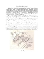
1.3 Elements of the AC Power System
The process of generating, distributing, and controlling the large amounts of power
required for a municipality or geographic area is highly complex. However, each
system, regardless of its complexity, is composed of the same basic elements with
the same basic goal: Deliver ac power where it is needed by customers. The primary
elements of an ac power system can be divided into the following general areas of
technology:
• Power transformers
•Power generators
• Capacitors
• Transmission circuits
• Control and switching systems, including voltage regulators, protection devices,
and fault isolation devices
The path that electrical power takes to end-users begins at a power plant, where
electricity is generated by one of several means and is then stepped-up to a high
volt
age (500 kV is common) for transmission on high-tension lines. Step-down
transformers reduce the voltage to levels appropriate for local distribution and even-
tual use by customers. Figure 1.7 shows how these elements interconnect to provide
ac power to consumers.
1.4 Power Transformers
The transformer forms the basis of all ac power-distribution systems. In the most
basic definition, a transformer is a device that magnetically links two or more cir-
cuits for time-varying voltage and current. Magnetic coupling has a number of
intrinsic advantages, including:
• DC isolation between the circuits
• The ability to match the voltage and current capability of a source to a load on the
other side
• The ability to change the magnitude of the voltage and current from one side of
the transformer to the other
I
b
V
b
10
3
Z
b
A=
© 1999 CRC Press LLC
Figure 1.7 A typical electrical power-generation and distribution system. Although
this schematic diagram is linear, in practice power lines branch at each voltage
reduction to establish the distribution network. (From [5]. Used with permission.)
• The ability to change the phases of voltage and current from one side of the
device to the other
1.4.1 Basic Principles
In 1831, English physicist Michael Faraday demonstrated the phenomenon of elec-
tromagnetic induction. The concept is best understood in terms of lines of force, a
convention Faraday introduced to describe the direction and strength of a magnetic
field. The lines of force for the field generated by a current in a loop of wire are
shown in Figure 1.8. When a second, independent loop of wire is immersed in a
changing magnetic field, a voltage will be induced in the loop. The voltage will be
proportional to the time rate of change of the number of force lines enclosed by the
loop. If the loop has two turns, such induction occurs in each turn, and twice the
voltage results. If the loop has three turns, 3 times the voltage results, and so on. The
concurrent phenomena of
mutual induction
between the coils and
self-induction
in
each coil form the basis of transformer action.
For a power transformer to do its job effectively, the coils must be coupled tightly
and must have high self-induction. That is, almost all the lines of force enclosed by
the primary also must be enclosed by the secondary, and the number of force lines
produced by a given rate of change of current must be high. Both conditions can be
© 1999 CRC Press LLC
Figure 1.8 The basic principles of electromagnetic induction.
met by wrapping the primary and secondary coils around an iron core, as Faraday
did in his early experiments. Iron increases the number of lines of force generated in
the transformer by a factor of about 10,000. This property of iron is referred to as
permeability
. The iron core also contains the lines so that the primary and secondary
coils can be separated spatially and still closely coupled magnetically.
With the principles of the transformer firmly established, American industrialist
George Westinghouse and his associates made several key refinements that made
practical transformers possible. The iron core was constructed of thin sheets of iron
cut in the shape of the letter E. Coils of insulated copper wire were wound and
placed over the center element of the core. Straight pieces of iron were laid across
the ends of the arms to complete the magnetic circuit. This construction still is com-
mon today. Figure 1.9 shows a common E-type transformer. Note how the low-volt-
age and high-voltage windings are stacked on top of each other. An alternative
configuration, in which the low-voltage and high-voltage windings are located on
separate arms of a core box, is shown in Figure 1.10.
In an ideal transformer, all lines of force pass through all the turns in both coils.
Because a changing magnetic field produces the same voltage in each turn of the
coil, the total voltage induced in a coil is proportional to the total number of turns. If
no energy is lost in the transformer, the power available in the secondary is equal to
the power fed into the primary. In other words, the product of current and voltage in
© 1999 CRC Press LLC
the primary is equal to the product of current and voltage in the secondary. Thus, the
two currents are inversely proportional to the two voltages, and therefore, inversely
proportional to the turns ratio between the coils. This expression of power and cur-
rent in a transformer is true only for an ideal transformer. Practical limitations pre-
vent the perfect transformer from being constructed.
The key properties of importance in transformer core design include:
• Permeability
• Saturation
• Resistivity
• Hysteresis loss
Permeability, as discussed previously, refers to the number of lines of force a
material produces in response to a given magnetizing influence. Saturation identifies
Figure 1.9 Physical construction of an E-shaped core transformer. The low- and
high-voltage windings are stacked as shown.
© 1999 CRC Press LLC
the point at which the ability of the core to carry a magnetic force reaches a limiting
plateau. These two properties define the power-handling capability of the core ele-
ment. Electrical resistivity is desirable in the core because it minimizes energy
losses resulting from
eddy currents
. In contrast, hysteresis undermines the efficiency
of a transformer. Because of the interactions among groups of magnetized atoms,
losses are incurred as the frequency of the changing magnetic field is increased.
Throughout the history of transformer development, the goal of the design engineer
has been to increase permeability, saturation, and resistivity, while decreasing hys-
teresis losses. A variety of core materials, including silicon iron in various forms,
have been used.
Transformer efficiency is defined as follows:
(1.9)
P
P
out
P
in
100×=
Figure 1.10 Transformer construction using a box core with physical separation
between the low- and high-voltage windings.
© 1999 CRC Press LLC
Where:
E
= efficiency in percent
P
out
= transformer power output in watts
P
in
= transformer power input in watts
Losses in a transformer are the result of copper losses in the windings and core
losses. The copper losses vary with the square of the current; the core losses vary
with the input voltage magnitude and frequency. Because neither of these quantities
depends on the power being consumed by the load, power transformers are rated by
the voltamperes (VA) that flow through them.
The regulation specification of a power transformer is a measure of the trans-
former’s ability to maintain a constant output voltage under varying loads. The pri-
mary voltage is held constant at the value required to produce the rated voltage on
the secondary at full load:
(1.10)
Where:
R
= regulation in percent
V
s0
= secondary voltage under no load
V
sfl
= secondary voltage under full load
Also bearing on transformer performance are electrical insulation and the cooling
system used. These two elements are intimately related because the amount of heat
that the core and conductors generate determines the longevity of the insulation; the
insulation itself—whether solid, liquid, or gas—serves to carry off some portion of
the heat produced. Temperatures inside a commercial transformer may reach 100°C,
the boiling point of water. Under such conditions, deterioration of insulating materi-
als can limit the useful lifetime of the device. Although oils are inexpensive and
effective as insulators and coolants, some oils are flammable, making them unac-
ceptable for units placed inside buildings. Chlorinated hydrocarbon liquids (PCBs)
were used extensively from the 1930s to the late 1970s, but evidence of long-term
toxic effects prompted a ban on their use. (See Section 10.3.) Some transformers
rely on air- or nitrogen-gas-based insulators. Such devices can be installed indoors.
The breakdown strength of gas sometimes is enhanced through the addition of small
quantities of fluorocarbons. Other dry transformers depend on cast-resin insulation
made of polymerizing liquids that harden into high-integrity solids. Progress in heat
removal is largely responsible for reducing the overall size of the transformer
assembly.
Modern high-power commercial transformers may operate at voltages of 750 kV
or more and can handle more than 1000 kVA. The expected lifetime of a commercial
R
V
s
0
V
sfl
–
V
sfl
100×=
© 1999 CRC Press LLC
power transformer ranges from 24 to 40 years. A typical three-phase oil-cooled
transformer is shown in Figure 1.11.
1.4.2 Counter-Electromotive Force
All transformers, generators, and motors exhibit the property of inductance. This
property is the result of a
counter-emf
that is produced when a magnetic field is
(a)
Figure 1.11 Construction of an oil-filled three-phase power transformer used for com-
mercial power distribution: (a) cutaway view; (b, next page) exterior view. (Drawing b
from [14]. Used with permission.)
© 1999 CRC Press LLC
developed around a coil of wire. Inductance presents an opposition to the change in
current flow in a circuit. This opposition is evident in the diagram shown in Figure
1.12. In a purely inductive circuit (containing no resistance), the voltage will lead
the current by 90°. However, because all practical circuits have resistance, the offset
will vary from one circuit to the next. Figure 1.13 illustrates a circuit in which volt-
age leads current by 30°. The angular separation between voltage and current is
referred to as the
phase angle
. The phase angle increases as the inductance of the
circuit increases. Any inductive circuit exhibits the property of inductance, includ-
ing electrical power-transmission and distribution lines. The
henry
(H) is the unit of
measurement for inductance. A circuit has a 1 H inductance if a current changing at
a rate of 1 A/s produces an induced counter-emf of 1 V.
In an inductive circuit with ac applied, an opposition to current flow is created by
the inductance. This opposition is known as
inductive reactance
(
X
l
). The inductive
reactance of a given ac circuit is determined by the inductance of the circuit and the
rate of current change. Inductive reactance can be expressed as:
X
l
= 2
π
f L
(1.11)
Where:
Figure 11b.
© 1999 CRC Press LLC
X
l
= inductive reactance in ohms
2
π
= 6.28, the expression for one sine wave of alternating current (0° to 360°)
f
= frequency of the ac source in hertz
L
= inductance of the circuit in henrys
(a)
(b)
(c)
Figure 1.12 Purely inductive circuit: (a) circuit diagram; (b) representative wave-
forms; (c) vector representation.
© 1999 CRC Press LLC
1.4.3 Full Load Percent Impedance
The
full load percent impedance
(FLPI) of a transformer is an important parameter
in power-supply system design. FLPI is determined by the construction of the core
and physical spacing between the primary and secondary windings. Typical FLPI
(a)
(b)
(c)
Figure 1.13 Resistive-inductive circuit: (a) circuit diagram; (b) representative wave-
forms; (c) vector representations.
© 1999 CRC Press LLC
values range from 1 percent to 5 percent. FLPI is a measure of the ability of a trans-
former to maintain its rated voltage with a varying load. The lower the FLPI, the
bet
ter the regulation. FLPI also determines the maximum fault current that the trans-
former can deliver. For example, if a 5 percent FLPI transformer supplying 5 A
nominal at the secondary is short-circuited, the device can, theoretically, supply 100
A at full voltage. A similar transformer with a 10 percent FLPI can supply only 50 A
when short-circuited. Typical short-circuit currents for a selection of small three-
phase transformers are listed in Table 1.1.
1.4.4 Design Considerations
As touched upon previously, permeability
µ
describes the ease with which magnetic
flux can be produced in a given material. More flux will be produced in a material
with a high permeability than in a one with a low permeability, given the same
amount of current and the same number of turns in the coil. The ratio of a material's
permeability to the permeability of free space, called
relative permeability
, is often
used [4]. The actual permeability, which has units of webers per ampere-turn-meter,
is found by multiplying the permeability of free space by the relative permeability.
The overall ability of a core to carry flux also depends on its size and shape, and
its cross-sectional area. This is described by
permeance
. The basic relationship of
permeance to permeability in a core is defined by
or (1.12)
Where:
P
= permeance
µ
= permeability of the material
A
= the cross-sectional area of the core
l
= the mean length of the flux path in the core
This equation assumes uniform flux distribution in the core and constant permeabil-
ity inside the core. It does not take into account the variations in the length of the
flux path from the inside of the core to the outside. The reciprocal of permeance is
reluctance
.
Figure 1.14 shows the magnetization curve for a typical ferromagnetic material.
Note that the curve follows two different paths, depending on whether the mag-
netizing force
H
is increasing or decreasing. This is called a
hysteresis curve
. It is
caused by the fact that the magnetic particles in the core need to be rotated and
realigned each time the polarity of the magnetizing force changes. This is why the
magnetic force must be reversed to reduce the flux density to zero.
As the magnetizing force
H
increases, the flux density increases up to a point,
and then the curve flattens out. In this flattened region only a small increase in the
flux density can be achieved, as illustrated in the figure. The core is said to be
satu-
P
µA
l
l
R
== R
l
µA
=
© 1999 CRC Press LLC
rated
. The flattening of the curve indicates that the permeability has decreased from
the value it had when there was only a small amount of flux passing through the
core.
To eliminate ambiguity in the voltage and current polarity at the input and output
of the transformer symbol, the
dot convention
is commonly used. In circuit dia-
Table 1.1 Full Load Percent Impedance Short-Circuit Currents for a Selection of
Three-Phase Transformers
DC Amps (kVa/
kV)
Full Load Percent
Impedance
Symmetrical Short-Circuit
Current
1 A 1 57.7
1 A 2 28.8
1 A 3 19.3
1 A 4 14.4
1 A 5 11.5
2 A 1 115.5
2 A 2 57.7
2 A 3 38.5
2 A 4 28.8
2 A 5 23.1
3 A 1 173.2
3 A 2 86.6
3 A 3 57.7
3 A 4 43.3
3 A 5 34.6
4 A 1 230.9
4 A 2 115.5
4 A 3 77.0
4 A 4 57.7
4 A 5 46.2
5 A 1 288.6
5 A 2 144.3
5 A 3 96.2
5 A 4 72.2
5 A 5 57.7
© 1999 CRC Press LLC
grams, a small dot is placed near one end of each coil, as shown in Figure 1.15. The
dot indicates a rise in voltage from the unmarked to the marked terminal on each
coil. Under this convention, current into the dot on the primary side is labeled as
having positive polarity, and current out of the dotted terminal on the other side is
assigned positive polarity. This means that the power flow must be into the trans-
former on one side, and out of the transformer on the other side.
1.4.5 The Ideal Transformer
Although no transformer is ideal in its characteristics, transformers approach their
ideal characteristics in the operating range for which they were designed. The ideal
transformer has no coil resistance and no core loses, so that it has no power loss [4].
It also has no leakage inductance, because the permeability of the core is infinite,
and the core material is able to carry an infinite amount of flux without saturating.
Therefore, the mutual inductance is also infinite. The capacitance in an ideal trans-
former is negligible. The equations for an ideal transformer are given as follows:
(1.13)
(1.14)
(1.15)
v
1
i
1
v
2
i
2
=
v
1
v
2
N
1
N
2
=
i
1
i
2
N
2
N
1
=
Figure 1.14 A typical magnetization curve.
(From [4]. Used with permission.)
© 1999 CRC Press LLC
(1.16)
Where:
v
1
= voltage in the primary
v
2
= voltage in the secondary
i
1
= current in the primary
i
2
= current in the secondary
N
1
= turns in the primary
N
2
= turns in the secondary
Z
1
= impedance of the primary
Z
2
= impedance of the secondary
Equation (1.16) gives the effect of the transformer on an impedance on the second-
ary side (multiplied by the square of the turns ratio). The magnitude of the imped-
ance as seen on the secondary side is referred to as the
reflected impedance
.
Equivalent circuits are often used to model the performance of transformers with
greater accuracy. Although equivalent circuits are not exact replicas of real trans-
formers, they are close enough to realize accurate results for most situations. The
complete transformer equivalent circuit is shown in Figure 1.16.
The leakage inductance of both coils has been modeled by an inductor in series
with the load, since the current is the coils also produces the leakage flux. These
inductances are labeled
L
p
and
L
s
, respectively. Notice that the leakage inductance
for the secondary side has been divided by the turns ratio
n
2
because it was reflected
to the primary side. Resistors
R
p
and
R
s
are placed in series with the load to repre-
sent the resistance of the conductors used to wind the coils. Again, the secondary
resistance is divided by the square of the turns ratio because it was reflected.
The mutual inductance is represented by shunt inductor,
L
m
, because the magne-
tizing current is not coupled to the load. Resistor
R
c
is also placed in shunt to repre-
sent the core loss resulting from hysteresis and eddy currents in the core. The stray
capacitances between turns of the coils are represented by a capacitor connected
across each pair of terminals. This capacitance is larger for coils with more turns.
Although the capacitance is actually distributed, it is lumped for the equivalent cir-
cuit, in order to simplify the analysis. The capacitance from one coil to the other is
Z
1
Z
2
N
1
N
2
2
=
Figure 1.15 Dotted schematic symbol for a
transformer. (From [4]. Used with permission.)