Engineering Tribology Episode 2 Part 9 ppsx
Bạn đang xem bản rút gọn của tài liệu. Xem và tải ngay bản đầy đủ của tài liệu tại đây (710.16 KB, 25 trang )
SOLID LUBRICATION AND SURFACE TREATMENTS 425
various test machines were also increased by the addition of suspended molybdenum
disulphide [49,50]. Although in most cases 1% concentration by weight of molybdenum
disulphide in oil is sufficient, improvements were still obtained at higher concentrations
reaching 5% [49].
0
50
100
150
10 100 1000 10
4
10
5
10
6
Number of cycles to disruption
Slip amplitude [µm]
Vacuum
evaporation
Sputtering
100V
bias
200V
bias
Ion
Plating
FIGURE 9.15 Comparison of the durability of a gold lubricant film produced by different
coating techniques under fretting conditions [46].
However, an increase in wear when molybdenum disulphide is added to oil has also been
reported [51]. Under moderate conditions of sliding speed and load where molybdenum
disulphide is not expected to improve lubrication, abrasive impurities in the solid lubricant
can cause rapid wear [51]. Silica in particular accentuates wear when in concentrations above
0.01%, and pyrites (iron sulphide) are also destructive [51]. The quality, i.e. cleanliness, of the
solid lubricant added to oil is therefore critical. Although solid lubricant additives are
suitable for extremes of loads and speeds, they are not suitable for reducing wear under
moderate conditions. Molybdenum disulphide suspensions provide a limited reduction in
friction and wear when added to an oil containing sulphur based additives or zinc
dialkyldithiophosphate. On the other hand, the presence of detergents or dispersants in the
oil, such as calcium sulphonate, inhibits the lubricating action of molybdenum disulphide
[48,50].
The mechanism of lubrication by molybdenum disulphide dispersed in oil has unfortunately
received very little attention. It is widely believed, however, that molybdenum disulphide
provides a complimentary role to surfactants. Where there is a worn surface devoid of
surfactant, it is hypothesized that molybdenum disulphide particles adhere to form a
lubricating film. A conceptual model of solid lubrication by molybdenum disulphide which
occurs only when there are no surfactants to block adhesion by lamellae of solid lubricant to
the worn surface is illustrated schematically in Figure 9.16.
It has been found that molybdenum disulphide lubricates by film formation on a worn
surface at high temperatures where all surfactants, both natural and artificial, are unlikely to
adsorb on worn surfaces [52]. However, evidence which confirms that molybdenum
disulphide is only effective beyond the desorption temperature of the specific surfactants is
absent from the published literature.
Solid lubricants are also used to improve the frictional characteristics of polymers [33]. In
general they do offer some improvement but the effectiveness of solid lubricants added to
polymers depends on the type of polymer used. The greatest improvements in polymer
friction and wear characteristics are achieved with polymers of moderate lubricity such as
nylon and polyimide [53]. For example, the addition of graphite to nylon results in a
TEAM LRN
426 ENGINEERING TRIBOLOGY
reduction of the coefficient of friction from 0.25 to 0.18 and a small reduction in wear [53]. On
the other hand, it has also been shown that molybdenum disulphide when added to nylon
oxidizes during wear and does not develop an effective transfer film [54]. Under these
conditions, the friction performance of nylon/molybdenum disulphide blend was found to
be inferior to plain nylon [54].
Adhesion blocked
by adsorbed films
Adsorbed film of surfactants
MoS
2
present below desorption temperature MoS
2
present above desorption temperature
Adhesion of lamella
Inter-lamellar sliding
Desorbed
surfactants
Inter-lamellar
sliding inhibited
FIGURE 9.16 Conceptual model of the mechanism of lubrication by molybdenum disulphide
suspended in oil.
In polyimides the addition of the same amount of graphite reduced the coefficient of friction
to less than half of pure polyimide and significantly reduced wear. Although molybdenum
disulphide showed the same reduction of coefficient of friction as graphite/polyimide blend
its reduction in wear rate was inferior to that of graphite/polyimide blend [53].
Improvements achieved by adding molybdenum disulphide and graphite to
polytetrafluoroethylene (PTFE) are very limited [55,56]. The coefficients of friction for PTFE
filled with graphite and molybdenum disulphide are very similar to that of unfilled PTFE
and slightly lower than those obtained with most other fillers [55].
Interest in graphite has recently been extended by the incorporation of carbon fibres into
polymers. Carbon fibres offer a unique combination of mechanical reinforcement and
lubricity [57]. It has been shown that a carefully formulated polyimide/carbon fibre composite
can sustain high contact loads and maintain a friction coefficient close to 0.2 at temperatures
reaching 300°C with very low wear rates [58,59].
9.3 WEAR RESISTANT COATINGS AND SURFACE TREATMENTS
Wear resistant coatings consist of carefully applied layers of usually hard materials which are
intended to give prolonged protection against wear. Abrasive wear, adhesive wear and
fretting are often reduced by wear resistant coatings. There are numerous methods of
applying hard materials. For example, sputtering and ion-plating are used in a similar
manner as in the deposition of solid lubricants to generate thin coatings. Other methods are
used to deposit very thick layers of hard material. Applications of wear resistant coatings are
found in every industry, and for example, include mining excavator shovels and crushers
[60], cutting and forming tools in the manufacturing industries [61], rolling bearings in
liquefied natural gas pumps [62], etc. In most of these applications, wear rather than friction is
the critical problem. Another benefit of hard-coating technology is that a cheap substrate
material can be improved by a coating of an exotic, high-performance material. Most
engineering items are made of steel and it is often found that some material other than steel
is needed to fulfil the wear and friction requirements. Many wear resistant materials are
brittle or expensive and can only be used as a coating, so improved coating technology has
extended the control of wear to many previously unprotected engineering components.
TEAM LRN
SOLID LUBRICATION AND SURFACE TREATMENTS 427
9.3.1 TECHNIQUES OF PRODUCING WEAR RESISTANT COATINGS
There are many different methods of applying wear-resistant or hard coatings to a metal
substrate currently in use [e.g. 63-65]. New techniques continue to appear as every available
technology is adapted to deposit a wear resistant coating more efficiently. The wear resistance
of a surface can also be improved by localized heat treatment, i.e. thermal hardening, or by
introducing alloying elements, e.g. nitriding or carburizing. Many of these methods have
been in use for many years but unfortunately suffer from the disadvantage that the substrate
needs to be heated to a high temperature. Carburizing, nitriding and carbonitriding in
particular suffer from this problem. Various coating techniques available with their principal
merits and demerits are listed in Table 9.1.
T
ABLE 9.1 Available techniques for modifying the surface to improve its tribological
characteristics.
Wide range of coating thicknesses, but adhesion to substrate is poor
and only certain materials can be coated by this technique
Physical and chemical
vapour deposition
Thin discrete coating; no limitations on materials
Ion implantation Thin diffuse coating; mixing with substrate inevitable
Thick coatings; coating material must be able to meltLaser glazing and alloying
Electroplating
Friction surfacing Simple technology but limited to planar surfaces; produces thick
metal coating
Explosive cladding Rapid coating of large areas possible and bonding to substrate is
good. Can give a tougher and thicker coating than many other
methods
Very thick coatings possible but control of coating purity is difficultThermal spraying
Suitable for very thick coatings only; limited to materials stable at
high temperatures; coated surfaces may need further preparation
Surface welding
The thinner coatings are usually suitable for precision components while the thicker coatings
are appropriate for large clearance components.
Coating Techniques Dependent on Vacuum or Gas at Very Low Pressure
Plasma based coating methods are used to generate high quality coatings without any
limitation on the coating or substrate material. The basic types of coating processes currently
in use are: physical vapour deposition (PVD), chemical vapour deposition (CVD) and ion
implantation. These coating technologies are suitable for thin coatings for precision
components. The thickness of these coatings usually varies between 0.1 - 10 [µm]. These
processes require enclosure in a vacuum or a low pressure gas from which atmospheric
oxygen and water have been removed. As mentioned already the use of a vacuum during a
coating process has some important advantages over coating in air. The exclusion of
contaminants results in strong adhesion between the applied coating and substrate and
greatly improves the durability of the coating.
· Physical Vapour Deposition
This process is used to apply coatings by condensation of vapours in a vacuum. The
extremely clean conditions created by vacuum and glow discharge result in near perfect
TEAM LRN
428 ENGINEERING TRIBOLOGY
adhesion between the atoms of coating material and the atoms of the substrate. Porosity is
also suppressed by the absence of dirt inclusions. PVD technology is extremely versatile.
Virtually any metal, ceramic, intermetallic or other compounds which do not undergo
dissociation can be easily deposited onto substrates of virtually any material, i.e. metals,
ceramics, plastics or even paper. Therefore the applications of this technology range from the
decorative to microelectronics, over a significant segment of the engineering, chemical,
nuclear and related industries. In recent years, a number of specialized PVD techniques have
been developed and extensively used. Each of these techniques has its own advantages and
range of preferred applications. Physical vapour deposition consists of three major
techniques: evaporation, ion-plating and sputtering.
Evaporation is one of the oldest and most commonly used vacuum deposition techniques.
This is a relatively simple and cheap process and is used to deposit coatings up to 1 [mm]
thick. During the process of evaporation the coating material is vaporized by heating to a
temperature of about 1000 - 2000°C in a vacuum typically 10
-6
to 1 [Pa] [64]. The source
material can be heated by electrical resistance, eddy currents, electron beam, laser beam or arc
discharge. Electric resistance heating usually applies to metallic materials having a low
melting point while materials with a high melting point, e.g. refractory materials, need
higher power density methods, e.g. electron beam heating. Since the coating material is in
the electrically neutral state it is expelled from the surface of the source. The substrate is also
pre-heated to a temperature of about 200 - 1600°C [64]. Atoms in the form of vapour travel in
straight lines from the coating source towards the substrate where condensation takes place.
The collisions between the source material atoms and the ambient gas atoms reduce their
kinetic energy. To minimize these collisions the source to substrate distance is adjusted so
that it is less than the free path of gas atoms, e.g. about 0.15 - 0.45 [m]. Because of the low
kinetic energy of the vapour the coatings produced during the evaporation exhibit low
adhesion and therefore are less desirable for tribological applications compared to other
vacuum based deposition processes. Furthermore, because the atoms of vapour travel in
straight lines to the substrate, this results in a ‘shadowing effect’ for surfaces which do not
directly face the coating source and common engineering components such as spheres, gears,
moulds and valve bodies are difficult to coat uniformly. The evaporation process is
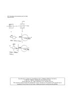
schematically illustrated in Figure 9.17.
Vacuum
pump
Resistance
heater
Coating
Substrate
Vapour
Coating material
(molten)
FIGURE 9.17 Schematic diagram of the evaporation process.
Ion-plating is a process in which a phenomenon known as ‘glow discharge’ is utilized. If an
electric potential is applied between two electrodes immersed in gas at reduced pressure, a
stable passage of current is possible. The gas between the electrodes becomes luminescent
hence the term ‘glow discharge’. When sufficient voltage is applied the coating material can
TEAM LRN
SOLID LUBRICATION AND SURFACE TREATMENTS 429
be transferred from the ‘source’ electrode to the ‘target’ electrode which contains the
substrate. The process of ion-plating therefore involves thermal evaporation of the coating
material in a manner similar to that used in the evaporation process and ionization of the
vapour due to the presence of a strong electric field and previously ionized low pressure gas,
usually argon. The argon and metal vapour ions are rapidly accelerated towards the substrate
surface, impacting it with a considerable energy. Under these conditions, the coating material
becomes embedded in the substrate with no clear boundary between film and substrate.
Usually prior to ion-plating the substrate is subjected to high-energy inert gas (argon) ion
bombardment causing a removal of surface impurities which is beneficial since it results in
better adhesion. The actual coating process takes place after the surface of the substrate has
been cleaned. However, the inert gas ion bombardment is continued without interruptions.
This causes an undesirable effect of decreasing deposition rates since some of the deposited
material is removed in the process. Therefore for the coating to form the deposition rate
must exceed the sputtering rate. The heating of the substrate by intense gas bombardment
may also cause some problems. The most important aspect of ion-plating which
distinguishes this process from the others is the modification of the microstructure and
composition of the deposit caused by ion bombardment [65]. Ion plating processes can be
classified into two general categories: glow discharge (plasma) ion plating conducted in a low
vacuum of 0.5 to 10 [Pa] and ion beam ion plating (using an external ionization source)
performed in a high vacuum of 10
-5
to 10
-2
[Pa] [64]. The ion-plating process is schematically
illustrated in Figure 9.18.
High
voltage
power
supply
−
+
Vacuum
pump
Resistance
heater
≈0.1 Pa
argon gas
Coating
Substrate
Plasma
Coating material
(molten)
FIGURE 9.18 Schematic diagram of the ion-plating process.
Sputtering is based on dislodging and ejecting the atoms from the coating material by
bombardment of high-energy ions of heavy inert or reactive gases, usually argon. In
sputtering the coating material is not evaporated and instead, ionized argon gas is used to
dislodge individual atoms of the coating substance. For example, in glow-discharge
sputtering a coating material is placed in a vacuum chamber which is evacuated to 10
-5
to 10
-3
[Pa] and then back-filled with a working gas, e.g. argon, to a pressure of 0.5 to 10 [Pa] [64]. The
substrate is positioned in front of the target so that it intercepts the flux of dislodged atoms.
Therefore the coating material arrives at the substrate with far less energy than in ion-plating
so that a distinct boundary between film and substrate is formed. When atoms reach the
substrate, a process of very rapid condensation occurs. The condensation process is critical to
coating quality and unless optimized by the appropriate selection of coating rate, argon gas
pressure and bias voltage, it may result in a porous crystal structure with poor wear
resistance.
The most characteristic feature of the sputtering process is its universality. Since the coating
material is transformed into the vapour phase by mechanical (momentum exchange) rather
TEAM LRN
430 ENGINEERING TRIBOLOGY
than a chemical or thermal process, virtually any material can be coated. Therefore the main
advantage of sputtering is that substances which decompose at elevated temperatures can be
sputtered and substrate heating during the coating process is usually negligible. Although
ion-plating produces an extremely well bonded film, it is limited to metals and thus
compounds such as molybdenum disulphide which dissociate at high temperatures cannot
be ion-plated. Sputtering is further subdivided into direct current sputtering, which is only
applicable to conductors, and radio-frequency sputtering, which permits coating of non-
conducting materials, for example, electrical insulators. In the latter case, a high frequency
alternating electric potential is applied to the substrate and to the ‘source’ material. The
sputtering process is schematically illustrated in Figure 9.19.
+
−
Vacuum
pump
≈1 Pa
argon gas
Coating
Substrate
Coating material
Bombardment
of coating
material by
gas ions
Dislodgement
of atoms
Plasma
RF generaor
or DC power
supply
Vapour
Deposition of
dislodged atoms
FIGURE 9.19 Schematic diagram of the sputtering process.
· Chemical Vapour Deposition
In this process the coating material, if not already in the vapour state, is formed by
volatilization from either a liquid or a solid feed. The vapour is forced to flow by a pressure
difference or the action of the carrier gas toward the substrate surface. Frequently reactant gas
or other material in vapour phase is added to produce a metallic compound coating. For
example, if nitrogen is introduced during titanium evaporation then a titanium nitride
coating is produced. The coating is obtained either by thermal decomposition or chemical
reaction (with gas or vapour) near the atmospheric pressure. The chemical reactions usually
take place in the temperature range between 150 - 2200°C at pressures ranging from 50 [Pa] to
atmospheric pressure [64]. Since the vapour will condense on any relatively cool surface that
it contacts, all parts of the deposition system must be at least as hot as the vapour source. The
reaction portion of the system is generally much hotter than the vapour source but
considerably below the melting temperature of the coating. The substrate is usually heated by
electric resistance, inductance or infrared heating. During the process the coating material is
deposited, atom by atom, on the hot substrate. Although CVD coatings usually exhibit
excellent adhesion, the requirements of high substrate temperature limit their applications to
substrates which can withstand these high temperatures. The CVD process at low pressure
allows the deposition of coatings with superior quality and uniformity over a large substrate
area at high deposition rates [64]. The CVD process is schematically illustrated in Figure 9.20.
· Physical-Chemical Vapour Deposition
This is a hybrid process which utilizes glow discharge to activate the CVD process. It is
broadly referred to as ‘plasma enhanced chemical vapour deposition’ (PECVD) or ‘plasma
assisted chemical vapour deposition’ (PACVD). In this process the techniques of forming
TEAM LRN
SOLID LUBRICATION AND SURFACE TREATMENTS 431
solid deposits by initiating chemical reactions in a gas with an electrical discharge are utilized.
Many of the phenomena characteristic to conventional high temperature CVD are employed
in this process. Similarly the same principles that apply to glow discharge plasma in
sputtering apply to CVD. In this process the coating can be applied at significantly lower
substrate temperatures, of about 100 - 600°C, because of the ability of high-energy electrons
produced by glow discharge, at pressures ranging from 1 to 500 [Pa], to break chemical bonds
and thus promote chemical reactions. Virtually any gas or vapour, including polymers, can
be used as source material [64]. For example, during this process a diamond coating can be
produced from carbon in methane or in acetylene [88]. Amorphous diamond-like coatings in
vacuum can attain a coefficient of friction as low as 0.006 [96]. Although contamination by air
and moisture tends to raise this coefficient of friction to about 0.02-0.07, the diamond-like
coating still offers useful wear resistance under these conditions [97-99]. The mechanism
responsible for such low friction is still not fully understood. The PECVD process is
schematically illustrated in Figure 9.21.
Resistance heater
Substrate
Exhaust
Coating
Inlet of reactant gases
FIGURE 9.20 Schematic diagram of the CVD process.
RF generator or
DC power supply
−
+
Substrate
Coating
Inlet of reactant gases
Exhaust
FIGURE 9.21 Schematic diagram of the PECVD process.
· Ion Implantation
The energy of ions in a plasma can be raised to much higher levels than is achieved either in
ion-plating or sputtering. If sufficient electrical potential is applied then the plasma can be
converted to a directed beam which is aimed at the material to be coated allowing the
controlled introduction of the coating material into the surface of the substrate. This process
is known as ion implantation. During the process of ion implantation, ions of elements, e.g.
nitrogen, carbon or boron, are propelled with high energy at the specimen surface and
penetrate the surface of the substrate. This is done by means of high-energy ion beams
containing the coating material in a vacuum typically in the range 10
-3
to 10
-4
[Pa]. A
specialized non-equilibrium microstructure results which is very often amorphous as the
original crystal structure is destroyed by the implanted ions [66]. The modified near-surface
TEAM LRN
432 ENGINEERING TRIBOLOGY
layer consists of the remnants of a crystal structure and interstitial implanted atoms. The
mass of implanted ions is limited by time, therefore compared to other surfaces, the layers of
ion-implanted surfaces are very shallow, about 0.01 to 0.5 [µm]. The thickness limitation of
the implanted layer is the major disadvantage of this method. The coatings generated by ion
implantation are only useful in lightly loaded contacts. The technique allows for the
implantation of metallic and non-metallic coating materials into metals, cermets, ceramics or
even polymers. The ion implantation is carried out at low temperatures. Despite the
thinness of the modified layer, a long lasting reduction in friction and wear can be obtained,
for example, when nitrogen is implanted into steel. The main advantage of the ion
implantation process is that the treatment is very clean and the deposited layers very thin,
hence the tolerances are maintained and the precision of the component is not distorted. Ion
implantation is an expensive process since the cost of the equipment and running costs are
high [64]. The ion implantation process is schematically illustrated in Figure 9.22.
Ions
Current
Filament:
coating
element
Non-ionized material retained
Ion accelerator
Ion separator
Electrostatic
flow controller
Raster on
substrate
Vacuum
pump
Magnets
Ionization
FIGURE 9.22 Schematic diagram of the ion implantation process.
More detailed information about surface coating techniques can be found in [45,64,65].
Coating Processes Requiring Localized Sources of Intense Heat
A localized intense source of heat, e.g. a flame, can provide a very convenient means of
depositing coating material or producing a surface layer of altered microstructure. Coating
methods in common use that apply this principle are surface welding, thermal spraying and
laser hardening or surface melting.
· Surface Welding
In this technique the coating is deposited by melting of the coating material onto the
substrate by a gas flame, plasma arc or electric arc welding process. A large variety of materials
that can be melted and cast can be deposited by this technique. During the welding process a
portion of the substrate surface is melted and mixed together with the coating material in the
fusion zone resulting in good bonding of the coating to the substrate. Welding is used in a
variety of industrial applications requiring relatively thick, wear resistant coatings ranging
from about 750 [µm] to a few millimetres [64]. Welding processes can be easily automated and
are capable of depositing coatings on both small components of intricate shape and large flat
surfaces.
TEAM LRN
SOLID LUBRICATION AND SURFACE TREATMENTS 433
There is a variety of specialized welding processes, e.g. oxyfuel gas welding (OGW), shielded
metal arc welding (SMAW), submerged arc welding (SAW), gas metal arc welding (GMAW),
gas tungsten arc welding (GTAW), etc., which are described in detail in [e.g. 64]. A schematic
diagram of the typical welding process is shown in Figure 9.23.
Completed
weld
Parent metal
Products o
f
combustion
protect
weld pool
Filler
wire
FIGURE 9.23 Schematic diagram of the welding process.
· Thermal Spraying
This is the most versatile process of deposition of coating materials. During this process the
coating material is fed to a heating zone where it becomes molten and then is propelled to
the pre-heated substrate. Coating material can be supplied in the form of rod, wire or powder
(most commonly used). The distance from the spraying gun to the substrate is in the range of
0.15 to 0.3 [m] [64]. The molten particles accelerated towards the substrate are cooled to a
semimolten condition. They splatter on the substrate surface and are instantly bonded
primarily by mechanical interlocking [64]. Since during the process a substantial amount of
heat is transmitted to the substrate it is therefore water cooled. There are a number of
techniques used to melt and propel the coating material and the most commonly applied are:
flame spraying, plasma spraying, detonation-gun spraying, electric arc spraying and others.
Flame Spraying utilizes the flame produced from combustion gases, e.g. oxyacetylene and
oxyhydrogen, to melt the coating material. Coating material is fed at a controlled rate into the
flame where it melts. The flame temperature is in the range of 3000 to 3500°C. Compressed
air is fed through the annulus around the outside of the nozzle and accelerates the molten or
semimolten particles onto the substrate. The process is relatively cheap, and is characterized
by high deposition rates and efficiency. The flame sprayed coatings, in general, exhibit lower
bond strength and higher porosity than the other thermally sprayed coatings. The process is
widely used in industry, i.e. for corrosion resistant coatings. A schematic diagram of this
process is shown in Figure 9.24.
Plasma Spraying is different from the plasma-based coating methods described previously
since the coating metal is deposited as molten droplets rather than as individual atoms or
ions. The technique utilizes an electric arc to melt the coating material and to propel it as a
high-velocity spray onto the substrate. In this process gases passing through the nozzle are
ionized by an electric arc producing a high temperature stream of plasma. The coating
material is fed to the plasma flame where it melts and is propelled to the substrate. The
temperature of the plasma flame is very high, e.g. up to 30,000°C and can melt any coating
TEAM LRN
434 ENGINEERING TRIBOLOGY
material, e.g. ceramics [89]. The highest temperatures are achieved with a monoatomic carrier
gas such as argon and helium. Molecular gases such as hydrogen and nitrogen produce lower
plasma temperatures because of their higher heat capacity. Therefore plasma spraying is
suitable for the rapid deposition of refractory compounds which are usually hard in order to
form thick hard surface coatings. The very high particle velocity in plasma spraying
compared to flame spraying results in very good adhesion of the coating to the substrate and
a high coating density. The application of an inert gas in plasma spraying gives high purity,
oxides free deposits. Although it is possible to plasma spray in open air the oxidation of the
heated metal powder is appreciable and the application of inert gas atmosphere is
advantageous. The quality of coating is critical to the wear resistance of the coating, i.e.
adhesion of the coating to the substrate and cohesion or bonding between powder particles in
the coating must be strong. These conditions often remain unfulfilled when the coating
material is deposited as partially molten particles or where the shrinkage stress on cooling is
allowed to become excessive [67]. Plasma spraying is commonly used in applications
requiring wear and corrosion resistant surfaces, i.e. bearings, valve seats, aircraft engines,
mining machinery and farm equipment. A schematic diagram of the plasma spraying process
is shown in Figure 9.25.
Wire feed
Fuel gases and oxygen
Compressed air
Semimolten spray stream
Water-cooled substrate
FIGURE 9.24 Schematic diagram of the flame spraying process.
Tungsten
electrodes
Plating
Powder feed
of coating material
Plasma flameSpark
Water
cooling
Water
cooling
Ar, He, H
2
, N
2
High voltage Substrate
FIGURE 9.25 Schematic diagram of the plasma spraying process.
Detonation-Gun Spraying is similar in some respects to flame spraying. The mixture of a
metered amount of coating material in a powder form with a controlled amount of oxygen
and acetylene is injected into the chamber where it is ignited. The powder particles are heated
TEAM LRN
SOLID LUBRICATION AND SURFACE TREATMENTS 435
and accelerated at extremely high velocities towards the substrate where they impinge. The
process is repeated several times per second. The coatings produced by this method exhibit
higher hardness, density and adhesion (bonding strength) than can be achieved with
conventional plasma or flame spraying processes. The coating porosity is also very fine.
Unfortunately very hard materials cannot be coated by this process because the high velocity
gas can cause surface erosion. Wear and corrosion resistant coatings capable of operating at
elevated temperatures are produced by this method. They are used in applications where
close tolerances must be maintained, i.e. valve components, pump plungers, compressor
rods, etc. A schematic diagram of this process is shown in Figure 9.26.
Semimolten spray stream
Water-cooled substrate
Powder,
acetylene
and oxygen
Valve
Spark plug
FIGURE 9.26 Schematic diagram of the detonation gun spraying process.
Electric Arc Spraying differs from the other thermal spraying processes since there is no
external heat source such as a gas flame or electrically induced plasma [64]. In this process an
electric arc is produced by two converging wire electrodes. Melting of the wires occurs at the
high arc temperature and molten particles are atomized and accelerated onto the substrate by
the compressed air. The use of an inert atomizing gas might result in improved
characteristics of some coatings by inhibiting oxidation. The wires are continuously fed to
balance the sprayed material. Since there is no flame touching the substrate like in the other
thermal spraying processes, the substrate heating is lower. The adhesion achieved during this
process is higher than that of flame sprayed coatings under comparable conditions. During
this process coatings of mixed metals, e.g. copper and stainless steel, can be produced. A
schematic diagram of this process is shown in Figure 9.27.
Semimolten spray stream
Water-cooled substrate
Electric
arc
Wire feed
Gas
(usually air)
FIGURE 9.27 Schematic diagram of electric arc spraying process.
TEAM LRN
436 ENGINEERING TRIBOLOGY
· Laser Surface Hardening and Alloying
Laser hardening is a form of thermal hardening where a high power laser beam, such as
from a carbon dioxide laser (with the beam power up to 15 [kW]), is scanned over a surface to
cause melting to a limited depth. Rapid cooling of the surface by the unheated substrate
results in a hard quenched microstructure with a fine grain size formed on re-solidification
[68,69]. Surface alloying is also possible if the surface of the substrate is pre-coated with the
alloying element or the alloying element is fed into the path of the laser beam. This process is
also known as laser cladding. The coating material is mixed together with the melted top
layer of the substrate and subsequently solidifies. Because of the very large temperature
gradients mixing of the molten material is intense. A strong bond between the modified
layer and the substrate is formed since the substrate is never exposed to any atmospheric
contaminants. For example, a stainless steel layer on a steel substrate can be produced by pre-
coating steel with chromium and then melting the surface with the laser beam. To produce a
500 [µm] thick layer of 1% stainless steel, a pre-coating of 5 [µm] thick chromium is required.
Although laser treatment can be performed in the open air the oxidation rate, e.g. of steel,
can be high and destructive. Therefore it is often preferable to apply this process in an inert
gas atmosphere. The process is particularly useful in applications where the access to the
surface to be treated is more easily achieved by the laser than any other method, e.g. a torch.
The area coverage by this process is relatively slow and the overlap areas between successive
laser passes have inferior properties and microstructure [89]. A schematic diagram of laser
surface alloying is shown in Figure 9.28.
Molten pad
up to 0.5 mm deep
Mixing
Substrate
Precoating
Quenched alloyed layer
High
power
laser
FIGURE 9.28 Schematic diagram of the laser surface alloying process.
Coating Processes Based on Deposition in the Solid State
It would be very convenient to directly join the coating material and substrate without
intermediate processes such as plasma-based coating. Under certain circumstances this is
possible although there are some comparatively severe limitations on the utility of such
methods. Two basic methods of direct joining or bonding are explosive bonding and friction
surfacing. These two methods do not require a carefully controlled environment or a
localized heat source and can be performed in the open air.
Friction Surfacing is an adaptation of friction welding where a material from a rod is bonded
to a flat surface by a combination of rotation and high contact force. It was discovered that if
the flat surface was moved while the rod was pressed against it and simultaneously rotated
then a layer of transferred material was deposited on the flat surface. This constituted a
relatively simple way of rapidly depositing a thick layer of metal [70]. Friction surfacing has
been studied as a simple and robust way of re-surfacing worn military and agricultural
equipment in remote areas such as the interior of Australia [70]. A major simplification of
this coating technology compared to other coating methods is that there is no necessity for
the exclusion of atmospheric oxygen during the coating process. However, the provision of
an inert gas atmosphere does improve adhesion or bonding between the coating and the
TEAM LRN
SOLID LUBRICATION AND SURFACE TREATMENTS 437
substrate [70]. Shape limitations of the substrate, i.e. that friction surfacing is only practicable
for plane surfaces or objects with axial symmetry, e.g. metal extrusions, as opposed to
complex surfaces, e.g. gear teeth, restricts the application of this otherwise promising and
simple coating technology. A schematic diagram of friction surfacing process is shown in
Figure 9.29a.
Explosive Cladding, also known as explosive bonding or explosive welding, is essentially a
solid-phase welding process during which bonding is produced by high velocity collision
between the substrate and coating material. The high velocity is achieved by controlled
explosion. In most cases, the coating material in the form of a sheet is placed at a small angle
of incidence to the substrate. A protective buffer, usually in the form of rubber sheet, is placed
on top of the coating material. When the explosives in the form of sheet or slurry are
detonated behind the buffer, contact between the sheet of coating material and the substrate
spreads out from the end of the sheet closest the substrate. A front forms at the edge of the
contact where the sheet is momentarily folded. Strong bonding of the cladding material is
facilitated by the expulsion of contaminants and oxide layers as a jet of fragmented or molten
material in front of the impacting metal surfaces. The removal of contaminants and oxides is
caused by the extremely high impact speed of the opposing surfaces during explosive
bonding. At the apex of the front, substrate and coating material melt. Since the metal flow
around the collision point is unstable and oscillating it often produces a rippled or wavy
interface between the substrate and the coating material. No external heat is required in this
process. Virtually any combination of metals and alloys, which otherwise cannot be bonded,
e.g. aluminium and steel, can be bonded by this process. Very high pressures of about 3 [GPa]
generated during the process restrict the thickness of the coatings to the layers thicker than
0.3 [mm] as thinner layers could rupture. The process is used in manufacturing, e.g. corrosion
resistant coatings for chemical, marine and petrochemical industries. The inconvenience of
explosives, the limitation of this method to large flat surfaces and the requirement for the
coating material to be tough does, however, severely curtail the usefulness of this technique.
A schematic diagram of the explosive bonding process is shown in Figure 9.29b.
Detonator
Detonation
Velocity
Explosive
Coating metal
Gap
Substrate
Jet of molten
metal oxides etc.
Bonded
Explosive cladding
Friction surfacing
Coating
metal
Hot
plastic
metal
Substrate
Contact force
Rotation
Frictional
heat
Deposited coating
Heat affected zone
Expelled
contaminants
b)
a)
Buffer
FIGURE 9.29 Schematic diagram of the coating processes based on deposition in the solid
state.
TEAM LRN
438 ENGINEERING TRIBOLOGY
Miscellaneous Coating Processes
There is a wide range of coating processes which are extensively used for applications
requiring resistance to corrosion and mild wear. These coating processes are very much
simpler and cheaper than the processes already described. For example, coatings can be
deposited by dipping the substrate in a coating material, spraying the coating material in an
atomized liquid form, e.g. the technique commonly used for paint applications, by utilizing
brush pad or roller, by chemical deposition or electroplating. Although the adhesion of these
coatings is sometimes not adequate for severe tribological applications they can be used as
corrosion resistant coatings and as soft, low shear strength solid lubricant and metallic
coatings for sliding wear applications.
Electroplating is a well established process with proven benefits in controlling corrosion and
wear resistance. This process is a convenient way of applying coatings of metals with high
melting points such as chromium, nickel, copper, silver, gold, platinum, etc., onto the
substrate. The electroplating system consists of an electrolytic bath, two electrodes and a DC
power source. A conducting solution which contains a salt or other compound of the metals
to be deposited is placed in the bath. When an electrical potential is applied to the electrodes,
i.e. one is the material to be coated the other is the donor electrode, the metal is deposited on
the substrate by electrochemical dissolution from the donor electrode as schematically
illustrated in Figure 9.30. Since, in general, the process is conducted under atmospheric
conditions and material is deposited with low energy, the coating-substrate adhesion is poor.
Coatings can be applied by this method to most metallic surfaces.
−
SO
4
−−
M
++
M
++
M
++
+
DC power
supply
Electron
flow
Electrolyte
e.g.
MSO
4
Coating metal
(anode)
Coated metal
(cathode)
Dashed line
shows original
shape
FIGURE 9.30 Schematic diagram of the electroplating process.
Application of Coatings and Surface Treatments in Wear and Friction Control
There is a wide range of coating techniques and careful selection of the appropriate coating
material and method is a pre-requisite for an effective coating. Prior to selecting the coating
material and method the first question to be asked is whether wear or friction is of greater
concern. If the prime objective is to reduce friction then a solid lubricant coating should be
selected and the coating method will, in most cases, be either sputtering or a combination of
painting and baking.
To suppress wear by the application of coatings, it is first necessary to determine the
mechanism of wear occurring, e.g. whether abrasive wear or some other form of wear is
present. Although most coatings can suppress several forms of wear, each type of coating is
most effective at preventing a few specific wear mechanisms. Therefore during the selection
process of the most effective coating to suppress wear in a particular situation, i.e. coating
optimization, the prevailing wear mechanism must first be recognized and assessed. The
basic characteristics of the coatings which can be achieved by the methods described in the
previous section in terms of wear control are summarized in Figure 9.31.
TEAM LRN
SOLID LUBRICATION AND SURFACE TREATMENTS 439
It can be seen from Figure 9.31 that while the optimization of a coating to resist abrasive wear
is relatively simple, i.e. it is sufficient to produce a thick hard surface layer with toughness
high enough to prevent coating fracture, other wear mechanisms require much greater care
in coating optimization.
Hard coating
Softer metal
a)
Resistant to · abrasive wear
· erosive wear
· cavitational wear
· rolling wear and contact fatigue
b)
Resistant to · adhesive wear
· corrosive wear
Non-metallic coating
Metal
Resistant to · adhesive wear
· fretting wear
· cavitational wear
Alloy
metal
Untreated, weaker microstructure
Transformed microstructure
c)
Resistant to · adhesive wear
· contact fatigue
· fretting wear and fretting fatigue
d)
Induced
compressive stress
Amorphous structure
FIGURE 9.31 Basic characteristics of coatings in terms of wear control.
Characteristics of Wear Resistant Coatings
Studies of wear resistant coatings reveal that hard coatings are most effective in suppressing
abrasive wear. An example of this finding is illustrated in Figure 9.32 which shows the wear
rate of a pump rotor as a function of the hardness of the coating applied to the surface. It can
be seen from Figure 9.32 that the abrasive wear rate declines to a negligible value once a PVD
coating of titanium nitride, which is characterized by extremely high hardness, is employed.
In this example abrasive wear was caused by very fine contaminants present in the pumped
fluid and the size of the abrasives was sufficiently small for a thin PVD coating to be effective.
In other applications where the abrasive particles are much larger, thicker coatings are more
appropriate.
0.5
1
2
5
10
20
200 500 1000 2000
Vickers hardness of rotor [kg/mm
2
]
Wear rate of rotor [µg/h]
Nitriding
TiN PVD
Tuftride treatment
FIGURE 9.32 Example of the resistance of a hard coating, TiN, to abrasion [60].
TEAM LRN
440 ENGINEERING TRIBOLOGY
It was also found that thin films of ceramics such as titanium nitride are quite effective in
suppressing adhesive wear in poorly lubricated and high stress contacts. For example, when a
cutting tool is coated with titanium nitride, adhesion and seizure between the tool and metal
chip does not occur even when cutting is performed in a vacuum [71]. Titanium nitride
coatings were also applied to gears and the scuffing tests on coated and uncoated gears
revealed that the critical load and scuffing resistance for coated gears is much higher [71,72].
This coating also reduces the coefficient of friction in unlubricated sliding as well as wear
rates, e.g. coefficients of friction close to 0.1 between titanium nitride and zirconium nitride
coatings on hardened bearing steel have been observed [73]. Unfortunately titanium nitride
coatings do not provide corrosion resistance [74]. Since zirconium and hafnium belong to the
same IVB group of the periodic table of chemical elements as titanium, some similarity in
wear properties of their compounds can be expected. In fact, hafnium nitride was found to
give the best wear resistance performance in tests on cutting tools [75]. Zirconium nitride is
also extremely useful as a coating [73,76]. It should also be mentioned that for hard coatings to
be effective an adequate substrate hardness is essential [63]. Therefore hardened steels and
materials such as stellite are generally used as a substrate for this type of coating.
Fretting wear can be mitigated by the use of hard coatings, e.g. carbides, especially at small
amplitudes of fretting movement [77]. However, at higher fretting amplitudes, spalling of the
carbide coatings renders them ineffective.
Coatings produced by ion implantation, in certain applications, can also provide large
reductions in wear. Since the coatings produced by this technique are very thin they are only
effective in reducing wear at low load levels as illustrated in Figure 9.33.
10
−9
10
−8
10
−7
10
−6
0.1 1 10520.50.2
Load [kg]
Wear rate [cm
3
/cm sliding distance]
Unimplanted
Implanted
FIGURE 9.33 Effect of nitrogen ion implantation on wear rates of stainless steel in
unlubricated sliding [78].
It can be seen from Figure 9.33 that in dry unlubricated sliding of stainless steel, nitrogen ion
implantation reduces the wear rate by a factor of ten or more at light loads. Nitrogen ion
implantation was found to be very efficient in reducing the wear and friction of titanium and
titanium alloys [79]. Titanium and its alloys are notorious for their susceptibility to seizure in
dry sliding, and implantation by nitrogen ions reduces the coefficients of friction in dry
sliding to a value as low as 0.15. It has also been found that nitrogen ion implantation is
effective in reducing the fretting wear and surface damage in stainless steel [80].
It is, however, difficult to give general rules for the applicability of the ion implantation
technique since the results are only specific to a particular combination of substrate and
implanted material. Since, there are about ten substrate metals in common use, e.g. steel, cast
iron, aluminium, copper, titanium, etc., and theoretically the entire periodic table of
TEAM LRN
SOLID LUBRICATION AND SURFACE TREATMENTS 441
elements is available for implantation, the number of combinations of test materials far
exceeds available resources and time. Currently the most commonly implanted elements are:
nitrogen, carbon and boron and the conclusions about the usefulness of ion implantation
may change as ‘new’ implantation elements are discovered, e.g. combined yttrium and
nitrogen implantation [81].
In some cases the incorrect choice of implantation material for coating may actually result in
increased wear rates. It has been shown that implantation of stainless steel by argon increased
the coefficient of friction from 0.8 to 1.0 in dry unlubricated sliding at room temperature
while implantation by boron reduced the coefficient of friction to about 0.15 [82]. The causes
of wear reduction by ion implantation are largely unknown.
It has been hypothesized that ion implantation causes surface hardening, passivation and
loss of adhesion [79]. Although the hardening is effective for pure metals, hardened alloys
such as martensitic steel are not hardened by ion implantation [79].
An interesting feature of nitrogen ion implantation is that the effect of implantation persists
after wear has exceeded the depth of implantation, in some cases by a factor of 10 or more [79].
It was observed that nitrogen migrated inwards with the wear surface [83]. As with other
characteristics of ion implantation this phenomenon is also poorly understood.
Surface hardening by high power lasers also results in reductions in wear for a wide range of
applications. For example, the flank and rake faces of a cutting tool made of high speed steel
showed less wear after laser hardening [84]. However, the reductions in wear achieved by the
application of laser hardening are not as dramatic as those obtained by nitride coatings. On
the other hand, laser hardening has been found to be very beneficial in the unlubricated
sliding of cast irons [85,86]. This effect is illustrated in Figure 9.34 where laser hardened cast
iron exhibits superior wear behaviour to untreated cast iron.
0
0.5
1.0
0
100
200
300
400
01020
Load [N]
Wear rate [× 10
−8
kg/m]
01020
Load [N]
01020
Load [N]
01020
Load [N]
Hypereutectic
flake
Eutectic
flake
Hypoeutectic
flake
Nodular
cast iron
Severe wear
Mild wear
As-cast
Laser
melted
FIGURE 9.34 Effect of laser hardening on the wear rates of various cast irons [85].
It can be seen from Figure 9.34, that the transition from mild to severe wear is suppressed by
laser hardening and the mitigation of wear at high loads is clear.
Laser surface alloying has also been found to effectively reduce wear under fretting. For
example, a zirconium alloyed layer formed on the surface of carbon steel caused a reduction
in the volume of fretting wear by at least a factor of 5 [87].
The performance of non-metallic coatings such as tungsten carbide used for rolling elements
is related to the operating conditions. For example, it was found that 100-200 [µm] thick
TEAM LRN
442 ENGINEERING TRIBOLOGY
plasma-sprayed coatings on steel and ceramic balls fail by surface wear when lubrication is
poor or by sub-surface delamination when lubrication is effective [93].
Wear-resistant coatings can be as vulnerable to oxidative wear as monolithic metal
substrates. For example, copper causes rapid wear of cutting tools coated with titanium
nitride, titanium carbide or a combination of both compounds. It was found that the primary
cause of rapid wear of the titanium nitride and carbide coatings is a catalytic effect of copper
on the oxidation of the nitride and carbide to titanium oxide which is then rapidly worn
away. In contrast, the oxidation of chromium nitride in air is much slower than titanium
nitride [94], thus permitting the chromium nitride to effectively protect machining tools
from wear by copper [95].
9.4 SUMMARY
Solid lubricants and surface treatments have rapidly evolved in recent decades from simple
and traditional methods to extremely sophisticated technologies. These developments are
part of an effort to eliminate the limitations imposed by oil-based lubrication and in the
process are changing the general perception of the limits of wearing contacts. Knowledge of
the mechanisms behind these improvements in lubrication and wear resistance is, in most
cases, very limited. The methods employed in most studies on surface coatings are empirical
and there is relatively little information available on which surface treatment is the most
suitable for a particular application. This is a new area subjected to extensive research and the
number of new surface treatments and coating technologies available to control friction and
wear is rapidly increasing.
REFERENCES
1 W.L. Bragg, Introduction to Crystal Analysis, G. Bell and Sons, London, 1928.
2 F.P. Bowden and D. Tabor, Friction and Lubrication of Solids, Part 1, Oxford University Press, 1954.
3 A.I. Bailey and J.S. Courtney-Pratt, Real Contact and Shear Strength of Monomolecular Layers, Proc. Roy.
Soc., London, Series A, Vol. 227, 1955, pp. 500-515.
4 F.P. Bowden and D. Tabor, Friction and Lubrication of Solids, Part 2, Oxford University Press, 1964.
5 R.F. Deacon and J.F. Goodman, Lubrication by Lamellar Solids, Proc. Roy. Soc., London, Series A, Vol. 243,
1958, pp. 464-482.
6 E.R. Braithwaite and J. Hickman, Dry Film Lubrication of Metals, Metal Industries, Vol. 104, 1964, pp. 190-
192.
7 H.E. Sliney, Dynamics of Solid Lubrication as Observed by Optical Microscopy, ASLE Transactions, Vol. 21,
1978, pp. 109-117.
8 Y. Tsuya, Lubrication with Molybdenum Disulfide Film Under Various Conditions, ASLE Transactions, Vol.
15, 1972, pp. 225-232.
9 A.I. Brudnyi and A.F. Karmadonov, Structure of Molybdenum Disulphide Lubricant Film, Wear, Vol. 33,
1975, pp. 243-249.
10 P.J. Bryant, P.L. Gutshall and L.H. Taylor, A Study of Mechanisms of Graphite Friction and Wear, Wear,
Vol. 7, 1964, pp. 118-126.
11 M.N. Gardos, The Synergistic Effects of Graphite on the Friction and Wear of Molybdenum Disulphide Films
in Air, Tribology Transactions, Vol. 31, 1988, pp. 214-227.
12 J.W. McCain, A Theory and Tester Measurement Correlation About Molybdenum Disulphide Dry Film
Lubricant Wear, Journal of Society of Aerospace, Material and Process Engineers, Vol. 6, 1970, pp. 17-28.
13 J.K. Lancaster, Lubrication by Transferred Films of Solid Lubricants, ASLE Transactions, Vol. 8, 1965, pp. 146-
155.
14 A.J. Haltner and C.S. Oliver, Frictional Properties of Some Solid Lubricant Films Under High Load, Journal
of Chemical Engineering Data, Vol. 6, 1961, pp. 128-130.
TEAM LRN
SOLID LUBRICATION AND SURFACE TREATMENTS 443
15 W.J. Bartz and J. Xu, Wear Behaviour and Failure Mechanism of Bonded Solid Lubricants, Lubrication
Engineering, Vol. 43, 1987, pp. 514-521.
16 G. Salomon, A.W.J. de Gee and J.H. Zaat, Mechano-Chemical Factors in Molybdenum Disulphide Film
Lubrication, Wear, Vol. 7, 1964, pp. 87-101.
17 J.W. Midgley and D.G. Teer, An Investigation of the Mechanism of the Friction and Wear of Carbon,
Transactions ASME, Journal of Basic Engineering, Vol. 85, 1963, pp. 488-494.
18 W.J. Bartz, Tribological Behaviour of Three Component Bonded Solid Lubricant Films, Proc. JSLE Int.
Tribology Conference, 8-10 July, 1985, Tokyo, Japan, Elsevier, pp. 419-424.
19 M. Campbell and V. Hopkins, Development of Polyimide Bonded Solid Lubricants, Lubrication Engineering,
Vol. 23, 1967, pp. 288-294.
20 R.D. Hubbel and B.D. McConnell, Wear Behaviour of Polybenzimidazole Bonded Solid-Film Lubricants,
Transactions ASME, Journal of Lubrication Technology, Vol. 92, 1970, pp. 252-257.
21 P.W. Centers, The Role of Oxide and Sulfide Additions in Solid Lubricant Compacts, Tribology Transactions,
Vol. 31, 1988, pp. 149-156.
22 G.W. Rowe, Some Observations on the Frictional Behaviour of Boron Nitride and Graphite, Wear, Vol. 3,
1960, pp. 274-285.
23 A.J. Haltner and C.S. Oliver, Effect of Water Vapour on the Friction of Molybdenum Disulphide, Ind. Eng.
Chem. Fundamentals, Vol. 5, 1966, pp. 348-355.
24 J. Gansheimer, Neue Erkenntnisse uber die Wirkungsweise von Molybdansulfid als Schmierstoff,
Schmiertechnik, Vol. 11, 1964, pp. 271-280.
25 H.H. Krause, S.L. Cosgrave and C.M. Allen, Phthalocyanines as High Temperature Lubricants, Journal of
Chemical Engineering Data, Vol. 6, 1961, pp. 112-118.
26 G. Salomon, A. Begelinger and A.W.J. De Gee, Friction Properties of Phthalocyanine Pigments, Wear, Vol. 10,
1967, pp. 383-396.
27 P.A. Grattan and J.K. Lancaster, Abrasion by Lamellar Solid Lubricants, Wear, Vol. 10, 1967, pp. 453-468.
28 R.L. Fusaro and H.E Sliney, Graphite Fluoride, a New Solid Lubricant, ASLE Transactions, Vol. 13, 1970, pp.
56-65.
29 R.L. Fusaro, Graphite Fluoride Lubrication: the Effect of Fluorine Content, Atmosphere and Burnishing
Technique, ASLE Transactions, Vol. 22, 1977, pp. 15-24.
30 P.M. Magie, A Review of the Properties and Potentials of the New Heavy Metal Derivative Solid
Lubricants, Lubrication Engineering, Vol. 22, 1966, pp. 262-269.
31 W.E. Jamison and S.L. Cosgrove, Friction Characteristics of Transition-Metal Disulfides and Di-Selenides,
ASLE Transactions, Vol. 14, 1971, pp. 62-72.
32 S. Hironaka, M. Wakihara, H. Einode, M. Taniguchi, T. Moriuchi and T. Hanzawa, Lubricity of Synthetic
Niobium Sulfides With Layer Structure, Proc. JSLE International Tribology Conf., 8-10 July 1985, Tokyo,
Japan, Elsevier, pp. 389-394.
33 F.J. Clauss, Solid Lubricants and Self-Lubricating Solids, Academic Press, New York, 1972.
34 A.J. Haltner, Sliding Behavior of Some Layer Lattice Compounds in Ultrahigh Vacuum, ASLE Transactions,
Vol. 9, 1966, pp. 136-148.
35 H.E. Sliney, T.N. Strom and G.P. Allen, Fluoride Solid Lubricants for Extreme Temperatures and Corrosive
Environments, ASLE Transactions, Vol. 8, 1965, pp. 307-322.
36 R.A. Burton and J.A. Russell, Forces and Deformations of Lead Films in Frictional Processes, Lubrication
Engineering, Vol. 21, 1965, pp. 227-233.
37 Y. Tsuya and R. Takagi, Lubricating Properties of Lead Films on Copper, Wear, Vol. 7, 1964, pp. 131-143.
38 S. Miyake and S. Takahashi, Small-Angle Oscillatory Performance of Solid-Lubricant Film-Coated Ball
Bearings for Vacuum Applications, ASLE Transactions, Vol. 30, 1987, pp. 248-253.
39 H. Kondo, K. Maeda and N. Tsushima, Performance of Bearings With Various Solid Lubricants in High
Vacuum and High Speed Conditions, Proc. JSLE, International Tribology Conf., 8-10 July 1985, Tokyo, Japan,
Elsevier, pp. 787-792.
40 H.E.Sliney, The Use of Silver in Self-Lubricating Coatings for Extreme Temperatures, ASLE
Transactions,Vol. 29, 1986, pp. 370-376.
TEAM LRN
444 ENGINEERING TRIBOLOGY
41 C. Della Corte and H.E. Sliney, Composition Optimization of Self-Lubricating Chromium-Carbide Based
Composite Coatings for Use to 760°C, ASLE Transactions, Vol. 30, 1987, pp. 77-83.
42 M.B. Petersen, S.F. Murray and J.J. Florek, Consideration of Lubricants for Temperatures Above 1000°F, ASLE
Transactions, Vol. 2, 1960, pp. 225-234.
43 R.M. Gresham, Solid-Film Lubricants: Unique Products for Unique Lubrication, Lubrication Engineering, Vol.
44, 1988, pp. 143-145.
44 T. Spalvins, Friction Characteristics of Sputtered Solid Film Lubricants, NASA TM X-52819, 1970.
45 D.H. Buckley, Surface Effects in Adhesion, Friction, Wear and Lubrication, Elsevier, Amsterdam 1981.
46 N. Ohmae, T. Tsukizoe and T. Nakai, Ion-Plated Thin Films for Anti-Wear Applications, Transactions
ASME, Journal of Lubrication Technology, 1978, Vol. 100, pp. 129-135.
47 P.J. Pacholke and K.M. Marshek, Improved Worm Gear Performance With Colloidal Molybdenum Disulfide
Containing Lubricants, Lubrication Engineering, Vol. 43, 1987, pp. 623-628.
48 W.J. Bartz and J. Oppelt, Lubricating Effectiveness of Oil-Soluble Additives and Molybdenum Disulfide
Dispersed in Mineral Oil, Lubrication Engineering, Vol. 36, 1980, pp. 579-585.
49 J. Gansheimer, Influence of Certain Vapours and Liquids on the Frictional Properties of Molybdenum
Disulphide, ASLE Transactions, Vol. 10, 1967, pp. 390-399.
50 W.J. Bartz, Influence of Extreme-Pressure and Detergent-Dispersant Additives on the Lubricating
Effectiveness of Molybdenum Disulphide, Lubrication Engineering, Vol. 33, 1977, pp. 207-215.
51 J.P. Giltrow, Abrasion by Impurities in MoS
2
, Part 2 - Practical Tests and the Development of a Quality
Control, Tribology International, Vol. 7, 1974, pp. 161-168.
52 R.J. Rolek , C. Cusano and H.E. Sliney, The Influence of Temperature on the Lubricating Effectiveness of MoS
2
Dispersed in Mineral Oils, ASLE Transactions, Vol. 28, 1985, pp. 493-502.
53 J.K. Lancaster, Dry Bearings: a Survey of Materials and Factors Affecting Their Performance, Tribology, Vol.
6, 1973, pp. 219-251.
54 W. Liu, C. Huang, L. Gao, J. Wang and H. Dang, Study of the Friction and Wear Properties of MoS
2
-filled
Nylon 6, Wear, Vol. 151, 1991, pp. 111-118.
55 K. Tanaka and S. Kawakami, Effect of Various Fillers on the Friction and Wear of Polytetrafluoroethylene-
Based Composites, Wear, Vol. 79, 1982, pp. 221-234.
56 M.B. Low, The Effect of the Transfer Film on the Friction and Wear of Dry Bearing Materials for a Power
Plant Application, Wear, Vol. 52, 1979, pp. 347-363.
57 J.P. Giltrow and J.K. Lancaster, Friction and Wear of Polymers Reinforced with Carbon Fibres, Nature
(London), Vol. 214, 1967, pp. 1106-1107.
58 R.L. Fusaro, Polyimides Formulated from a Partially Fluorinated Diamine for Aerospace Tribological
Applications, NASA, TM-83339, 1983.
59 R.L. Fusaro and W.F. Hady, Tribological Properties of Graphite-Fiber-Reinforced Partially Fluorinated
Polyimide Composites, ASLE Transactions, Vol. 29, 1986, pp. 214-222.
60 S. Asanabe, Applications of Ceramics for Tribological Components, Tribology International, Vol. 20, 1987, pp.
355-364.
61 E. Bergmann, J. Vogel and R. Brink, Criteria for the Choice of a PVD Treatment for the Solution of Wear
Problems, Proc. Int. Tribology Conference, Melbourne, The Institution of Engineers, Australia, National
Conference Publication No. 87/18, December, 1987, pp. 65-74.
62 M. Tomaru, Application of Surface Treatment on Rolling Bearings, Transactions JSLE, Vol. 31, 1986, pp. 593-
594.
63 W.H. Roberts, Surface Engineering, Proc. Int. Tribology Conference, Melbourne, The Institution of Engineers,
Australia, National Conference Publication No. 87/18, December, 1987, pp. 438-451.
64 B. Bhushan and B.K. Gupta, Handbook of Tribology, Materials, Coatings and Surface Treatments, McGraw-
Hill, Inc., 1991.
65 R.F. Bunshah (editor), Deposition Technologies for Films and Coatings, Developments and Applications,
Noyes Publications, 1982.
TEAM LRN
SOLID LUBRICATION AND SURFACE TREATMENTS 445
66 A.E. Berkowitz, W.G. Johnston, A. Mogro-Campero, J.L. Walter and H. Bakhru-Suny, Structure and
Properties Changes During Ion Bombardment of Crystalline Fe
75
B
25
, Metastable Materials Formation by Ion
Implantation, Proceedings of the Materials Research Society, Annual Meeting, November 1981, Boston,
U.S.A., editors: S.T. Picraux and W.J. Choyke, Elsevier Science Publ. Co. New York, 1982, pp. 195-202.
67 M.M. Mayuram and R. Krishnamurthy, Tribological Characteristics of Sprayed Surfaces, Proc. Int. Tribology
Conference, Melbourne, The Institution of Engineers, Australia, National Conference Publication No. 87/18,
December, 1987, pp. 203-207.
68 S.T. Picraux and E.L. Pope, Tailored Surface Modification by Ion Implantation and Laser Treatment, Science,
Vol. 224, 1984, pp. 615-622.
69 C.T. Walters, A.H. Clauer and B.P. Fairand, Pulsed Laser Surface Melting of Fe-Base Alloys, Proc. 2nd Int.
Conf. on Rapid Solidification Processing: Principles and Technologies, 23-26 March 1980, editors: R.
Mehrabian, B.H. Kear and M. Cohen, Reston, Virginia, U.S.A., Baton Rouge, Claitor's Publ. Division, L.A.,
1980, pp. 241-245.
70 E.M. Jenkins and E.D. Doyle, Advances in Friction Deposition - Low Pressure Friction Surfacing, Proc. Int.
Tribology Conference, Melbourne, The Institution of Engineers, Australia, National Conference Publication
No. 87/18, December, 1987, pp. 87-94.
71 A. Douglas, E.D. Doyle and B.M. Jenkins, Surface Modification for Gear Wear, Proc. Int. Tribology Conference,
Melbourne, The Institution of Engineers, Australia, National Conference Publication No. 87/18, December, pp.
52-58.
72 Y. Terauchi, H. Nadano, M. Kohno and Y. Nakamoto, Scoring Resistance of TiC and TiN-Coated Gears,
Tribology International, Vol. 20, 1987, pp. 248-254.
73 S. Ramalingam and S. Kim, Tribological Characteristics of Arc Coated Hard Compound Films, Proc. Int.
Tribology Conference, Melbourne, The Institution of Engineers, Australia, National Conference Publication
No. 87/18, December, pp. 403-408.
74 Y.W. Lee, Adhesion and Corrosion Properties of Ion-Plated TiN, Proc. 6th Int. Conf. on Ion and Plasma
Assisted Techniques, Brighton, U.K., C.E.P. Consultants, Edinburgh, 1987, pp. 249-251.
75 J.J. Oakes, A Comparative Evaluation of HfN, Al
2
O
3
, TiC and TiN Coatings on Cemented Carbide Tools, Thin
Solid Films, Vol. 107, 1983, pp. 159-165.
76 R.G. Duckworth, Hot Zirconium Cathode Sputtered Layers for Useful Surface Modification, First
International Conference on Surface Engineering, Brighton U.K., 25-28 June 1985, Paper 42, pp. 167-177, Publ.
Welding Institute, Abingdon, U.K.
77 R.C. Bill, Fretting Wear and Fretting Fatigue, How are They Related?, Transactions ASME, Journal of
Lubrication Technology, Vol. 105, 1983, pp. 230-238.
78 G. Dearnaley, The Ion-implantation of Metals and Engineering Materials, Transactions Institute of Metal
Finishing, Vol. 56, 1978, pp. 25-31.
79 C.J. McHargeu, Ion Implantation in Metals and Ceramics, International Metals Reviews, Vol. 31, 1986, pp. 49-
76.
80 J.P. Hirvonen and J.W. Mayer, Fretting Wear of Nitrogen-Implanted AISI 304 Stainless Steel, Materials
Letters, 1986, Vol. 4, pp. 404-408.
81 G. Dearnaley, Adhesive, Abrasive and Oxidative Wear in Ion-Implanted Metals, Materials Science and
Engineering, Vol. 69, 1985, pp. 139-147.
82 M. Hirano and S. Miyake, Boron and Argon Ion Implantation Effect on the Tribological Characteristics of
Stainless Steel, Proc. JSLE. Int. Tribology Conference, 8-10 July, 1985, Tokyo, Japan, Elsevier, pp. 245-250.
83 E. Lo Russo, P. Mazzoldi, I. Scotoni, C. Tosello and S. Tosto, Effect of Nitrogen-Ion Implantation on the
Unlubricated Sliding Wear of Steel, Applied Physics Letters, Vol. 34, 1979, pp. 627-629.
84 Ming-Jen Hsu and P.A. Mollian, Cutting Tool Wear of Laser-Surface-Melted High Speed Steels, Wear, Vol.
127, 1988, pp. 253-268.
85 P.W. Leech, Comparison of the Sliding Wear Process of Various Cast Irons in the Laser-Surface-Melted and
as-Cast Forms, Wear, Vol. 113, 1986, pp. 233-245.
86 W.J. Tomlinson, R.F. O'Connor and T.A. Spedding, Running-in Wear of a Grey Cast Iron and the Effect of Laser
Transformation Hardening, Tribology International, Vol. 21, 1988, pp. 302-308.
87 A.W. Batchelor, G.W. Stachowiak, G.B. Stachowiak, P.W. Leech and O. Reinhold, Control of Fretting
Friction and Wear of Roping Wire by Laser Surface Alloying and Physical Vapour Deposition Coatings,
Wear, Vol. 152, 1992, pp. 127-150.
TEAM LRN
446 ENGINEERING TRIBOLOGY
88 J.C. Angus, Diamond and Diamond-Like Films, Thin Solid Films, Vol. 216, 1992, pp. 126-133.
89 B.C. Oberlander and E. Lugscheider, Comparison of Properties of Coatings Produced by Laser Cladding and
Conventional Methods, Materials Science and Technology, Vol. 8, 1992, pp. 657-665.
90 J.K. Lancaster, Transfer Lubrication for High Temperatures, A Review, Trans. ASME. Journal of Tribology,
Vol. 107, 1985, pp. 437-443.
91 T. Kayaba, K. Kato and H. Ohsaki, The Lubricating Properties of Friction-Coating Films of Pb-Sn Alloys in
High Vacuum, Proc. JSLE International Tribology Conference, Tokyo, 8-10, July 1985, Vol. 1, Japan Society of
Lubrication Engineers, Tokyo, 1985, pp. 209-214.
92 A.W. Batchelor, N.L. Loh and M. Chandrasekaran, Lubrication of Stellite at Ambient and Elevated
Temperatures by Transfer Films from a Graphite Slider, Wear, Vol. 198, 1996, pp. 208-215.
93 R. Ahmed and M. Hadfield, Rolling Contact Performance of Plasma Sprayed Coatings, Wear, Vol. 220, 1998,
pp. 80-91.
94 H. Ichimura and A. Kawana, High Temperature Oxidation of Ion-Plated CRN Films, Journal of Materials
Research, Vol. 9 (1), 1994, pp. 151-155.
95 T. Sato, T. Besshi, D. Sato and K. Inouchi, Evaluation of Wear and Tribological Properties of Coatings
Rubbing Against Copper, Wear, Vol. 220, 1998, pp. 154-160.
96 C. Donnett, M. Belin, J.C. Auge, J.M. Martin, A. Grill and V. Patel, Tribochemistry of Diamond-Like Carbon
Coatings in Various Environments, Surface and Coatings Techn., Vol. 68/69, 1994, pp. 626-631.
97 K H. Habig, Fundamentals of Tribological Behaviour of Diamond, Diamond-Like Carbon and Cubic Boron
Nitride Coatings, Surface and Coatings Techn., Vol. 76/77, 1995, pp. 540-547.
98 E.I. Meletis, A. Erdemir and G.R. Fenske, Tribological Characteristics of DLC Films and Duplex plasma
Nitriding/DLC Coating Treatment, Surface and Coatings Techn., Vol. 73, 1995, pp. 39-45.
99 K. Holmberg, J. Koskinen, H. Ronkainen, J. Vihersalo, J P. Hirvonen and J. Likonen, Tribological
Characteristics of Hydrogenated and Hydrogen-Free Diamond-Like Carbon Coatings, Diamond Films and
Techn., Vol. 4, 1994, pp. 113-129.
TEAM LRN
10
FUNDAMENTALS
CONTACT
BETWEEN SOLIDS
OF
10.1 INTRODUCTION
Surfaces of solids represent a very complex form of matter, far more complicated than a mere
plane. There is a variety of defects and distortions present on any real surface. These surface
features, ranging from bulk distortions of the surface to local microscopic irregularities, exert
a strong influence on friction and wear. The imperfections and features of a real surface
influence the chemical reactions which occur with contacting liquids or lubricants while the
visible roughness of most surfaces controls the mechanics of contact between the solids and
the resulting wear. The study of surfaces is relatively recent and the discoveries so far give
rise to a wide range of questions for the technologist or tribologist, such as: what is the
optimum surface? Is there a particular type of optimum surface for any specific application?
Why are sliding surfaces so prone to thermal damage? How can wear particles be formed by
plastic deformation when the operating loads between contacting surfaces are relatively very
low? Although some of these questions can be answered with the current level of
knowledge, the others remain as fundamental research topics. The characteristics of friction
are also of profound importance to engineering practice. Seemingly mundane phenomena,
such as the difference between static and kinetic friction, are still not properly understood
and their control to prevent technical problems remains imperfect. The basic question: what
is the mechanism of ‘stick-slip’?, i.e. the vibration of sliding elements caused by a large
difference between static and kinetic friction, has yet to be answered. In this chapter, the
nature of solid surfaces, contact between solids and its effects on wear and friction are
discussed.
10.2 SURFACES OF SOLIDS
At all scales of size, surfaces of solids contain characteristic features which influence friction,
wear and lubrication in a manner independent of the underlying material. There are two
fundamental types of features of special relevance to wear and friction:
· atomic-scale defects in a nominally plain surface which provide a catalytic effect for
lubricant reactions with the worn surface;
· the surface roughness which confines contact between solids to a very small
fraction of the nominally available contact area.
TEAM LRN
448 ENGINEERING TRIBOLOGY
Surfaces at a Nano Scale
Any surface is composed of atoms arranged in some two dimensional configuration. This
configuration approximates to a plane in most cases but there are nearly always significant
deviations from a true plane. The atoms of the solid body can be visualized as hard spheres
packed together with no loose space. To form an exact plane or perfectly flat exterior surface,
the indices of the crystal planes should be orientated to allow a layer of atoms to lie parallel to
the surface. Since this is rarely the case the atom layers usually lie inclined to the surface. As
a result a series of terraces is formed on the surface generating a quasi-planar surface [1]. The
terraces between atom layers are also subjected to imperfections, i.e. the axis of the terrace
may deviate from a straight path and some atoms might be missing from the edge of the
terrace. Smaller features such as single atoms missing from the surface or an additional
isolated atom present on the surface commonly occur. This model of the surface is known in
the literature as the ‘terrace ledge kink’ (TLK) model. It has been suggested that close contact
between surface atoms of opposing surfaces is hindered by this form of surface morphology.
Consequently wear and friction are believed to be reduced in severity by the lack of interfacial
atomic contact [2]. The TLK surface model and contact between two opposing real surfaces are
shown schematically in Figure 10.1.
Terrace ledge kink model Contact between opposing real surfaces
Atoms of body A
Atoms of body B
FIGURE 10.1 TLK surface model and contact between two opposing real surfaces (adapted
from [2]).
TLK surface features such as terraces, ledges, kinks, missing atoms and ‘ad-atoms’ provide a
large number of weakly bonded atoms. Atoms present on the surface have a lower bonding
strength than interior atoms because they have a lower number of adjacent atoms. It has
been observed that without all of these imperfections surfaces would probably be virtually
inert to all chemical reactants [3]. These surface features facilitate chemical reactions between
the surface and the lubricant. The reaction between lubricant and surface often produces a
surface layer or ‘film’ which reduces friction and wear. Furthermore, the substrate material
may be deformed plastically, which increases the number of dislocations reaching the surface.
Dislocations form strong catalytic sites for chemical reactions and this effect is known as
‘mechanical activation’ [4]. An intense plastic deformation at a worn surface is quite common
during wear and friction and the consequent mechanical activation can exert a strong
influence on the formation of a lubricating film.
The composition of surface atoms may be quite different from the nominal or bulk
composition since the alloying elements and impurities in a material tend to segregate at the
surface. For example, carbon, sulphur and silicon tend to segregate in steel, while aluminium
will segregate in copper [5]. Most materials, e.g. steel or copper, are not manufactured to a
condition of thermodynamic or chemical equilibrium. Materials tend to be manufactured at
a high temperature where impurities are relatively soluble, and then they are cooled rapidly
to ambient temperature. Therefore most engineering materials contain a supersaturated
solution of impurities which tend to be gradually released from the solvent material. Surface
heating and chemical attack by lubricants during sliding contact also contribute to
TEAM LRN
FUNDAMENTALS OF CONTACT BETWEEN SOLIDS 449
accentuation of surface segregation of contaminants and secondary moieties [6]. Another
factor which influences surface segregation of impurities is plastic deformation below the
annealing temperature of the worn metal [7]. Intense deformation of the material below the
worn surface takes place in unlubricated sliding contacts and the resulting increased
dislocation density is believed to provide a dense network of crystal lattice defects which
facilitate the diffusion of impurity atoms. Quite large effects on friction and wear with
relatively small alloying additions to pure metals have been observed and surface analysis
revealed that significant changes in the friction and wear coefficients are usually
accompanied by surface segregation [5].
Surface Topography
Surface imperfections at an atomic level are matched by macroscopic deviations from
flatness. Almost every known surfaces, apart from the cleaved faces of mica [8], are rough.
Roughness means that most parts of a surface are not flat but form either a peak or a valley.
The typical amplitude between the peaks and valleys for engineering surfaces is about one
micrometre. The profile of a rough surface is almost always random unless some regular
features have been deliberately introduced. The random components of the surface profiles
look very much the same whatever their source, irrespectively of the absolute scale of size
involved [9]. This is illustrated in Figure 10.2 where a series of surface roughness profiles
extracted from machined surfaces and from the surface of the earth and the moon (on a large
scale) are shown.
1mm of a roller-bearing race
30mm of a ball-bearing raceway
110mm of a lathe bed
18km of earth topography
3033km of moon topography
FIGURE 10.2 Similarities between random profiles of rough surfaces whether natural or
artificial (adapted from [9]).
Another unique property of surface roughness is that, if repeatedly magnified, increasing
details of surface features are observed down to the nanoscales. Also the appearance of the
surface profiles is the same regardless of the magnification [9,10]. This self-similarity of
surface profiles is illustrated in Figure 10.3.
TEAM LRN