beginning opengl game programming 2004 phần 4 ppsx
Bạn đang xem bản rút gọn của tài liệu. Xem và tải ngay bản đầy đủ của tài liệu tại đây (767.97 KB, 39 trang )
// Now we set the viewing transformation with the glTranslatef() function.
// We move the modeling transformation to (0.0, 0.0, -10.0), moving the
// world 10 units along the negative z-axis, which effectively moves the
// camera to the position (0.0, 0.0, 10.0).
glTranslatef(0.0f, 0.0f, -10.0f);
// draw a triangle at the origin
glBegin(GL_TRIANGLE);
glVertexf(10.0f, 0.0f, 0.0f);
glVertexf(0.0f, 10.0f, 0.0f);
glVertexf(-10.0f, 0.0f, 0.0f);
glEnd();
}
In this case, there isn’t a serious difference in code from the
gluLookAt()
function because
all you are doing is moving the camera along the z axis. But if you were orienting the cam-
era at an odd angle, you would need to use the
glRotate()
function as well (you will see
more of
glTranslate()
and
glRotate()
soon), which leads to the next way of manipulating
the camera: your own custom routines.
Creating Your Own Custom Routines
Suppose you want to create your own flight simulator. In a typical flight simulator, the
camera is positioned in the pilot’s seat, so it moves and is oriented in the same manner as
the plane. Plane orientation is defined by pitch, yaw, and roll, which are rotation angles
relative to the center of gravity of the plane (in your case, the pilot/camera position).
Using the modeling-transformation functions, you could create the following function to
create the viewing transformation:
void PlaneView(GLfloat planeX, GLfloat planeY, GLfloat planeZ, // the plane’s position
GLfloat roll, GLfloat pitch, GLfloat yaw) // orientation
{
// roll is rotation about the z axis
glRotatef(roll, 0.0f, 0.0f, 1.0f);
// yaw, or heading, is rotation about the y axis
glRotatef(yaw, 0.0f, 1.0f, 0.0f);
// pitch is rotation about the x axis
glRotatef(pitch, 1.0f, 0.0f, 0.0f);
// move the plane to the plane’s world coordinates
glTranslatef(-planeX, -planeY, -planeZ);
}
Chapter 4
■
Transformations and Matrices94
04 BOGL_GP CH04 3/1/04 9:58 AM Page 94
TLFeBOOK
Using this function places the camera in the pilot’s seat of your airplane regardless of the
orientation or location of the plane. This is just one of the uses of your own customized
routines. Other uses include applications of polar coordinates, such as rotation about
a fixed point, and use of the modeling-transformation functions to create what is
called “Quake-like movement,” where the mouse and keyboard can be used to control the
camera.
The greatest degree of camera control can be obtained by manually constructing and
loading your own matrices, which will be covered in the next section.
Using Your Own Matrices
Up until now, we’ve talked about functions that allow you to modify the matrix stacks
without really having to worry about the matrices themselves. This is great because it
allows you to do a lot without having to understand matrix math, and the functions
OpenGL provides for you are actually quite powerful and flexible. Eventually, though, you
may want to create some advanced effects that are possible only by directly affecting the
matrices. This will require that you know your way around matrix math, which we’re
assuming as a prerequisite to reading this book. However, we’ll at least show you how to
load your own matrix, how to multiply the top of the matrix stack by a custom matrix,
and one example of using a custom matrix.
Loading Your Matrix
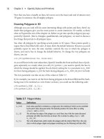
Before you can load a matrix, you need to specify it. OpenGL
matrices are column-major 4 × 4 matrices of floating point
numbers, laid out as in Figure 4.18.
Because the matrices are 4 × 4, you may be tempted to
declare them as two-dimensional arrays, but there is one
major problem with this. In C and C++, two-dimensional
arrays are row major. For example, to access the bottom-left
element of the matrix in Figure 4.18, you might think you’d
use
matrix[3][0]
, which is how you’d access the bottom-left
corner of a 4 × 4 C/C++ two-dimensional array. Because OpenGL matrices are column
major, however, you’d really be accessing the top-right element of the matrix. To get the
bottom-left element, you’d need to use
matrix[0][3]
. This is the opposite of what you’re
used to in C/C++, making it counterintuitive and error prone. Rather than using two-
dimensional arrays, it’s recommended that you use a one-dimensional array of 16 ele-
ments. The n
th
element in the array corresponds to element mn in Figure 4.18.
Using Your Own Matrices 95
Figure 4.18 OpenGL’s
column-major matrix format.
04 BOGL_GP CH04 3/1/04 9:58 AM Page 95
TLFeBOOK
As an example, if you want to specify the identity matrix (something you’d never need to
do in practice due to the
glLoadIdentity()
function), you could use
GLfloat identity[16] = { 1.0, 0.0, 0.0, 0.0, 0.0, 1.0, 0.0, 0.0, 0.0, 0.0, 1.0, 0.0,
0.0, 0.0, 0.0, 1.0 };
That’s easy enough. So, now that you’ve specified a matrix, the next step is to load it. This
is done by calling
glLoadMatrix()
, which has two flavors:
void glLoadMatrix{fd}(const TYPE matrix[16]);
When
glLoadMatrix()
is called, whatever is at the top of the currently selected matrix stack
is replaced with the values in the
matrix
array, which is a 16-element array as specified
previously.
Multiplying Matrices
In addition to loading new matrices onto the matrix stack (and thus losing whatever infor-
mation was previously in it), you can multiply the contents of the active matrix by a new
matrix. Again, you’d specify your custom matrix as above and then call the following:
void glMultMatrix{fd}(const TYPE matrix[16]);
Again,
matrix
is an array of 16 elements.
glMultMatrix()
uses post-multiplication; in other
words, if the active matrix before the call to
glMultMatrix()
is Mold, and the new matrix is
Mnew, then the new matrix will be Mold × Mnew. Note that the ordering is important;
because matrix multiplication is not commutative, Mold × Mnew in most cases will not
have the same result as Mnew × Mold.
Transpose Matrices
Extension
Extension name:
ARB_transpose_matrix
Name string:
GL_ARB_transpose_matrix
Promoted to core: OpenGL 1.3
Function names:
glLoadTransposeMatrixfARB()
,
glLoadTransposeMatrixdARB()
,
glMultTrans-
poseMatrixfARB()
,
glMultTransposeMatrixdARB()
Tokens:
GL_MODELVIEW_MATRIX_ARB
,
GL_PROJECTION_MATRIX_ARB
,
GL_TEXTURE_MATRIX_ARB
,
GL_COLOR_MATRIX_ARB
Chapter 4
■
Transformations and Matrices96
04 BOGL_GP CH04 3/1/04 9:58 AM Page 96
TLFeBOOK
We mentioned earlier that OpenGL uses column-major matrices, which conflicts with the
row-major two-dimensional arrays used by C and C++. In OpenGL 1.3, two new func-
tions were introduced that allow you to use row-major matrices instead:
glLoadTransposeMatrix{fd}(const TYPE matrix[16]);
glMultTransposeMatrix{fd}(const TYPE matrix[16]);
These functions work exactly the same way as
glLoadMatrix()
and
glMultMatrix()
,except
that the matrices are the transposition of what OpenGL uses internally. By using them,
you can specify your matrices as two-dimensional arrays in C or C++ and address the
matrix elements in an intuitive way.
Summary
In this chapter, you learned how to manipulate objects in your scene by using transfor-
mations. You’ve also examined how to change the way in which the scene itself is viewed,
through setting up projections. In the process, you’ve learned about the projection and
modelview matrices and how to manipulate them using both built-in functions and
matrices you define yourself. You now have the means to place objects in a 3D world, to
move and animate them, and to move around the world.
What You Have Learned
■
Transformations allow you to move, rotate, and manipulate objects in a 3D world,
while also allowing you to project 3D coordinates onto a 2D screen.
■
The viewing transformation specifies the location of the camera.
■
The modeling transformation moves objects around the 3D world.
■
The projection transformation defines the viewing volume and clipping planes.
■
The viewport transformation maps the projection of the scene into the viewport,
or window, on your screen.
■
The OpenGL modelview transformation is a combination of the modeling and
viewing transformations.
■
The viewpoint is also called the “camera” or “eye coordinates.”
■
Translation is the act of moving an object along a vector.
■
Rotation is the act of rotating an object about a vector-defined axis.
■
Scaling is the act of increasing or decreasing the size of an object.
■
Perspective projection shows 3D worlds exactly as you see things in real life.
Objects that are farther away appear smaller than objects that are closer to the
camera.
Summary 97
04 BOGL_GP CH04 3/1/04 9:58 AM Page 97
TLFeBOOK
■
Orthographic projection shows objects on the screen in their true size, regardless
of their distance from the camera.
■
The modelview matrix defines the coordinate system that is used to place and
orient objects. You set the modelview matrix to the current matrix by using the
glMatrixMode()
function with
GL_MODELVIEW
as the parameter. Using
GL_PROJECTION
as
the parameter sets the current matrix to the projection matrix.
■
glLoadIdentity()
restores the current matrix to the identity matrix.
■
Translation is performed in OpenGL with the
glTranslate()
function.
■
Rotation is performed in OpenGL with the
glRotate()
function.
■
Scaling is performed in OpenGL with the
glScale()
function.
■
Saving and restoring the current matrix is accomplished via the
glPushMatrix()
and
glPopMatrix()
functions.
■
The
glOrtho()
and
gluOrtho2D()
functions are used to set up orthographic
projections.
■
The
glFrustum()
and
gluPerspective()
functions are used to set up perspective
projections.
■
gluLookAt()
can be used to position and orient the OpenGL viewpoint.
■
Use the
glLoadMatrix()
function to load a user-defined matrix as the current
OpenGL matrix.
■
Use the
glMultMatrix()
function to multiply the current OpenGL matrix by a
user-defined matrix.
Review Questions
1. Write the line of code to position an object at the point (29, 3, 15).
2. Write the line of code to rotate an object 45 degrees about the x axis.
3. Write the lines of code to a) triple the size of an object and b) halve the size of an
object.
4. What are the four types of matrix stacks?
5. What function restores the current matrix to the identity matrix?
6. What do the
glPushMatrix()
and
glPopMatrix()
functions accomplish?
On Your Own
1. Write a function that positions and rotates a cube, given as parameters the (x, y, z)
position of the cube and the rotation angles about each axis. You can assume that
the function to draw the cube is
DrawCube()
, and the prototype of your function is
void PositionAndRotate(float xPos, float yPos, float zPos, float xAngle, float
yAngle, float zAngle);
Chapter 4
■
Transformations and Matrices98
04 BOGL_GP CH04 3/1/04 9:58 AM Page 98
TLFeBOOK
99
Colors, Lighting,
Blending, and Fog
chapter 5
A
world without color would be pretty boring, not to mention confusing and
depressing. Likewise, moving around in a 3D world drawn in shades of black and
white on a computer screen would get to be rather monotonous for most people.
It wouldn’t be particularly realistic. Fortunately, OpenGL offers plenty of magic to fill
your world with color.
This chapter begins by taking a look at how basic colors work in OpenGL. Then we’ll
move on to more realistic colors using lighting and materials. Then we’ll look at how
transparency and other effects can be achieved through blending. Finally, we’ll take a look
at OpenGL’s built-in fog support, which can be used to both create realism and improve
performance. As you can see, the fun is just beginning!
In this chapter, you’ll learn about:
■
Colors in OpenGL
■
Shading
■
OpenGL lighting
■
Light sources
■
Materials
■
Blending and transparency
■
Fog
Using Colors in OpenGL
When you pass primitives to OpenGL, it assigns colors to them by one of two methods:
using lighting or using the current color. When lighting is used, the color for each vertex
05 BOGL_GP CH05 3/1/04 10:16 AM Page 99
TLFeBOOK
is computed based on a number of factors, including the position and color of one or
more lights, the current material, the vertex normal, and so on. If lighting is disabled, then
the current color is used instead. In RGBA mode, which is what you’ll almost always be
using, OpenGL keeps track of a primary and a secondary color consisting of red, green,
blue, and alpha components.
Note
The alternative to RGBA mode is
color-index
mode. In color-index mode, rather than specifying
color values directly, you specify indices into a palette of colors maintained by the windowing sys-
tem. Unless you intend to target very old computers, you can ignore color-index mode entirely.
Because it is no longer relevant, we won’t be covering it here.
In this chapter you’ll first learn about how to use the current color, and later on about
lighting.
Setting the Color
In RGBA mode, you specify colors by indicating the intensity of the red, green, and blue
components. There is also an optional fourth component, called alpha, which is usually
used for transparency. We’ll discuss using the alpha value later in this chapter.
The color components are usually expressed using floating point values, with 0.0 being the
minimum intensity and 1.0 being the maximum. So black would be represented by set-
ting the red, green, and blue components to 0.0, whereas white would be represented by
setting all three components to 1.0.
To specify the primary color in OpenGL, you will use one of the many variations of
glColor*()
:
void glColor{34}{bsifd ubusui}(T components);
void glColor{34}{bsifd ubusui}v(T components);
The first set of functions takes each color component individually, whereas the second set
of functions takes them in an array of the appropriate size. The byte, short, and integer
versions of
glColor()
internally remap the values to a floating point value, so that the max-
imum possible integer value is mapped to 1.0 and the minimum value is mapped to 0.0.
When using the versions of
glColor()
that take only three components, the alpha value is
automatically set to 1.0.
Let’s look at a few samples of how
glColor()
is used. The following calls all set the current
primary color to yellow.
// using floats
glColor3f(1.0, 1.0, 0.0);
Chapter 5
■
Colors, Lighting, Blending, and Fog100
05 BOGL_GP CH05 3/1/04 10:16 AM Page 100
TLFeBOOK
// using unsigned bytes
glColor3ui(255, 255, 0);
// using signed bytes in an array
GLbyte yellow[] = {127, 127, 0};
glColor3iv(yellow);
The primary color is used to determine vertex colors when lighting is not enabled. Every
time you specify a vertex using
glVertex()
, the current primary color is checked and
applied to that vertex. You can change the color as often as you like, although if you
change it more than once between vertices, only the last change will have an effect.
Tip
At first glance, using the primary color might not seem terribly useful. Directly specifying a color for
each vertex might work well for simple demos, but most things in the real world can’t be described
accurately using such a simple model. However, it does have practical applications. For example, in
most games, many of the lights and most of the geometry are static, i.e. they don’t change from
frame to frame. Rather than redundantly recomputing lighting every frame, one common solution
is to compute it before the program is run—possibly using a more realistic lighting model than
that used by most graphics APIs, such as radiosity—and then store—or “bake”—the computed
value into the vertex data as the vertex color. Then, when the geometry is displayed, this value is
combined with textures and possibly dynamic lighting to produce the final color.
Secondary Color
Extension
Extension name:
EXT_secondary_color
Name string:
GL_EXT_secondary_color
Promoted to core: OpenGL 1.4
Function names:
glSecondaryColor{msifd ubusui}EXT
,
glSecondaryColor{msifd ubusui}vEXT
Tokens:
GL_COLOR_SUM_EXT
In addition to a primary color, OpenGL keeps track of a secondary color, which was added
in OpenGL 1.4. The secondary color came about as the result of adding separate specular
color, which we’ll cover later in this chapter. Because vertices had to carry around a sec-
ond piece of color information anyway, the OpenGL designers decided to allow develop-
ers to make use of it even when they aren’t using lighting. The secondary color is
interpolated across the primitive and added to the fragment color after the texture envi-
ronment has been applied—which simply means that the secondary color is added after
Using Colors in OpenGL 101
05 BOGL_GP CH05 3/1/04 10:16 AM Page 101
TLFeBOOK
everything else. The one main difference between the primary and secondary colors is that
the secondary color does not include an alpha component.
The secondary color can be set using one of the following:
glSecondaryColor3{bsifd ubusui}(TYPE red, TYPE green, TYPE blue);
glSecondaryColor3{bsifd ubusui}v(TYPE color);
By default, the secondary color is not used during rasterization when lighting is disabled.
To make use of the secondary color, you need to enable it as follows:
glEnable(GL_COLOR_SUM);
Among other things, you can use this to specify the specular component if you’re doing
lighting yourself.
Shading
So far, we have talked about using
glColor()
to set the color at each vertex. But how does
OpenGL decide what color to use for pixels in the middle of a triangle? If all three vertices
are the same color, then it should be obvious that every pixel in the triangle should use
that color as well. But what happens if you use a different color for each vertex of a prim-
itive?
To find out, let’s consider a line with two vertices of different colors. We’ll keep things sim-
ple and say that the first vertex is black and the second vertex is white. So what is the color
of the line itself? This answer comes from what is known as the shading model.
Shading can either be flat or smooth. When flat shading is used, the entire primitive is
drawn with a single color. With the exception of points, primitives are drawn using more
than one vertex. Because each vertex may have a different color, OpenGL has to choose
one of them to use for the primitive’s color. For lines, triangles, and quads, the color of the
last vertex is used. For line strips and line loops, the color of the second vertex in each
individual segment is used. For triangle strips and fans and quad strips, the color of the
last vertex in each sub-triangle or quad is used. For polygons, the color of the first vertex
is used.
Smooth shading, based on the Gouraud shading model, is the more realistic of the two and
uses interpolation to determine the colors between the vertices of a primitive. This process
will be made clearer as we continue with the line example.
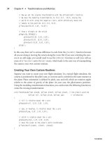
If we use flat shading on our sample line, the line will be white because the last vertex
specified is white. However, if we use smooth shading, then our line will progress from the
color black at the first vertex to gray at the middle of the line to white at the second ver-
tex. This effect is illustrated in Figure 5.1.
Chapter 5
■
Colors, Lighting, Blending, and Fog102
05 BOGL_GP CH05 3/1/04 10:16 AM Page 102
TLFeBOOK
As you can see, interspersed between the first vertex and the middle of the line are pro-
gressively lighter shades of gray. The progression continues on the other half of the line as
the colors shift through lighter shades of gray until you reach white.
The idea of smooth shading with polygonal primitives is essentially the same as smooth
shading with a line. For example, drawing the triangle using smooth shading with a dif-
ferent color for each vertex yields a triangle where each vertex color progressively changes
to the other two vertices’ colors as it moves across the polygon’s surface. Smooth shading
is useful for simulating the effect of a curved surface when lighting is enabled.
Now that you know what these shading modes are all about, how do you use them? The
glShadeModel()
function lets you specify the current shading model before you begin draw-
ing. It is defined as:
glShadeModel(GLenum mode);
You can specify either
GL_SMOOTH
for smooth shading or
GL_FLAT
for flat shading as the mode
parameter. The default setting is
GL_SMOOTH
.
So with this information, you can now create some code that will draw a smooth-shaded
triangle.
// use smooth shading
glShadeModel(GL_SMOOTH);
// draw our smooth-shaded triangle
glBegin(GL_TRIANGLES);
glColor3f(1.0f, 0.0f, 0.0f); // red vertex
glVertex3f(–10.0f, -10.0f, –5.0f);
glColor3f(0.0f, 1.0f, 0.0f); // green vertex
glVertex3f(20.0f, -10.0f, –5.0f);
glColor3f(0.0f, 0.0f, 1.0f); // blue vertex
glVertex3f(–10.0, 20.0f, -5.0f);
glEnd();
Shading 103
Figure 5.1 Smooth shading of a line with black at the first
vertex and white at the second vertex.
05 BOGL_GP CH05 3/1/04 10:16 AM Page 103
TLFeBOOK
The output is shown in Figure 5.2 (refer to the CD for
a full-color version). The red, green, and blue colors
from each of the vertices progressively change as they
move across the triangle’s surface. In the middle, the
three colors converge to create the color gray, which
means that the three colors (RGB) are each at the same
intensity.
A Colorful Example
The sample program from this section, which you’ll
find in the Colors directory in the Chapter 5 folder,
illustrates the use of colors and shading. Figure 5.3
shows the same quad drawn four times. The top row
uses flat shading, the bottom uses smooth, the right
column uses secondary color, and the left column does
not.
Lighting in OpenGL
You have now arrived at one of the most important
aspects of 3D graphics: lighting. It is one of the few
elements that can make or break the realism of your
3D game. So far, you’ve looked at how to build objects,
move objects, put color on objects, and shade them.
Now let’s look at how to make these objects come to
life with materials, lights, and lamps.
OpenGL Lighting and the Real World
Let’s take a quick step back and look at a simple explanation of how light works in the real
world. Light sources, such as the sun or a light bulb, produce photons of many different
wavelengths, covering the full spectrum of colors. Many of these photons strike objects,
which absorb some of them and reflect others, depending on what the object is made of.
The reflected photons may be reflected fairly uniformly if the object has a smooth surface,
or they may be scattered if the surface is rough. The reflected photons may then strike
other objects, and the process continues. We are able to see the world around us because
some of these photons eventually enter our eyes.
Modeling the complex interaction of light photons and even a fairly small number of
objects is computationally expensive. Although it is certainly possible to create a computer-
based model of real-world lighting that very accurately models nature, the methods for
doing so are too expensive to be used in games and other real-time applications. For this
Chapter 5
■
Colors, Lighting, Blending, and Fog104
Figure 5.2 A smooth-shaded
triangle with red, green, and blue
vertices.
Figure 5.3 A quad drawn with
four different shading and color
settings.
05 BOGL_GP CH05 3/1/04 10:16 AM Page 104
TLFeBOOK
reason, OpenGL and other graphics libraries use simplified lighting models that trade
accuracy for speed. Although the results do not match the real world exactly, they are close
enough to be believable. If you would rather have more accurate lighting than that which
OpenGL provides, you can do your own calculations either by passing pre-lit vertices to
OpenGL or by using your own custom calculations through the use of a vertex program.
OpenGL calculates lighting by approximating the light into red, green, and blue compo-
nents. This means that the color a light emits is determined by the amount of red, green,
and blue light it emits. Light is further broken down into four different terms, which
together attempt to simulate the major effects of real-world lighting:
■
Ambient light simulates light bouncing between surfaces so many times that the
source of the light is no longer apparent. This component is not affected by the
position of either the light or the viewer.
■
Diffuse light comes from a certain direction, but once it strikes a surface, it is
reflected equally in all directions. The diffuse lighting component is affected by the
position or direction of the light, but not the position of the viewer.
■
Specular light is directional and reflected off a surface in a particular direction.
Specularity is often referred to as shininess. The specular term is affected by the
position of both the light and the eye.
■
Emissive light is a cheap way to simulate objects that emit light. OpenGL does not
actually use the emissive term to illuminate surrounding objects; it simply causes
the emissive object to be more intensely lit.
The final results of lighting depend on several major factors, each of which is discussed in
detail in this section. The factors are
1. One or more light sources. Each light source will have the ambient, diffuse, specu-
lar, and emissive terms listed above, each specified as RGBA values. In addition,
they will either have a position or direction or have terms that affect attenuation
and may have a limited area of effect (for example, a spotlight).
2. The orientation of surfaces in the scene. This is determined through the use of
normals, which are associated with each vertex.
3. The material each object is made of. Material properties define what percentages of
the RGBA values of each lighting term should be reflected. They also define how
shiny the surface is.
4. The lighting model, which includes a global ambient term (independent of any
light source), whether or not the position of the viewer has an effect on lighting
calculations, and other parameters.
When the light strikes a surface, OpenGL uses the material of the surface to determine the
percentage of red, green, and blue light that should be reflected by the surface. Even
Lighting in OpenGL 105
05 BOGL_GP CH05 3/1/04 10:16 AM Page 105
TLFeBOOK
though they are approximations, the equations used by OpenGL can be computed rather
quickly and produce reasonably good results.
Light Sources
It’s time to turn on the lights and get on with the show! The first thing you need to do to
take advantage of OpenGL’s lighting is to enable it, which is done as follows:
glEnable(GL_LIGHTING);
This call causes the lighting equation to be applied to every vertex, but it does not actu-
ally turn on any lights. You need to explicitly turn on any lights you’ll be using by calling
glEnable()
:
glEnable(GL_LIGHTx);
x
takes on a numeric value ranging from 0 to a maximum value that can vary across dif-
ferent OpenGL implementations. You’re guaranteed to always have at least eight lights,
though, so
GL_LIGHT0
through
GL_LIGHT7
are always valid. If you want to find out whether
or not more than eight lights are available, you can pass
GL_MAX_LIGHTS
to
glGet()
:
GLint maxLights;
glGetIntegerv(GL_MAX_LIGHTS, &maxLights);
Tip
Eight lights may not seem like a lot; you certainly have more than eight in your home. There are
good reasons for keeping the maximum number of lights relatively small, though. First of all, light-
ing is fairly expensive. Even enabling three or four lights can have a noticeable impact on your
frame rate. Second, OpenGL’s lights are really needed only for
dynamic lighting
. Dynamic lighting
is used when either the light source is moving or one or more of the objects being lit are moving.
Only a small percentage of game objects fit into this category; everything else can use
static light-
ing
. Because static lighting doesn’t change, it can be calculated in advance, usually by a 3D mod-
eling program or other external tool, and encoded within the model vertex data. Finally, if you really
need more than eight lights (or the implementation-defined maximum, if more than eight), it’s
unlikely that any one object needs to be lit by more than eight lights, so you can update each light
as needed on a per-model basis.
Assigning Light Properties
Each light has several properties associated with it that define its position or direction in
the world, the colors of its ambient, diffuse, specular, and emissive terms, and whether the
light radiates in all directions or is limited to a spotlight-like cone. These properties are
controlled through
glLight()
:
glLight{fi}(GLenum light, GLenum pname, type param);
glLight{fi}v(GLenum light, GLenum pname, const type *params);
Chapter 5
■
Colors, Lighting, Blending, and Fog106
05 BOGL_GP CH05 3/1/04 10:16 AM Page 106
TLFeBOOK
light
identifies which light’s properties you are modifying and uses
GL_LIGHTx
, as in the
previous section. The next several sections cover each of the possible values of
pname
and
the
params
associated with them, which are summarized in Table 5.1.
Position and Direction
Each light can have either a position or a direction. Lights with a position are often called
positional or point lights. Directional lights represent lights that are infinitely far away.
There are no true directional lights in nature, since nothing is infinitely far away, but
some light sources are far enough away that they can be treated as directional lights. The
sun is an excellent example of this. The main advantage to using directional lights is that
they simplify the lighting calculation. With positional lights, you have to calculate the
direction vector between the light source and the surface. With directional lights, the
direction is the same for every surface. Even so, the extra cost associated with positional
lights is necessary and worth it for lights that truly are positional, which includes almost
every light source you can actually see in your game. Use whichever form is appropriate
for the light in question.
You set a light’s position using
GL_POSITION
, passing a four-element vector of the form (x,
y, z, w). x, y, and z represent either the position or direction. The w term is used to indi-
cate whether this is a directional or positional light. If it is 0.0, it is directional. Otherwise,
it is positional. The following code shows you how to set up a directional light pointing
down the negative y axis.
GLfloat lightDir[] = { 0.0, 1.0, 0.0, 0.0 };
glLightfv(GL_LIGHT0, GL_POSITION, lightDir);
Lighting in OpenGL 107
Table 5.1 glLight*() Parameters
Parameter Meaning
GL_AMBIENT
Ambient intensity of light
GL_DIFFUSE
Diffuse intensity of light
GL_SPECULAR
Specular intensity of light
GL_POSITION
Position of light as vector (x, y, z, w)
GL_SPOT_DIRECTION
Direction of spotlight as vector (x, y, z)
GL_SPOT_EXPONENT
Spotlight exponent
GL_SPOT_CUTOFF
Spotlight cutoff angle
GL_CONSTANT_ATTENUATION
Constant attenuation value
GL_LINEAR_ATTENUATION
Linear attenuation value
GL_QUADRATIC_ATTENUATION
Quadratic attenuation value
05 BOGL_GP CH05 3/1/04 10:16 AM Page 107
TLFeBOOK
To set up a positional light located at (2, 4, –3), you’d use the following:
GLfloat lightPos[] = { 2.0, 4.0, -3.0, 1.0 };
glLightfv(GL_LIGHT0, GL_POSITION, lightDir);
The default position for all lights is (0, 0, 1, 0), which is directional, pointing down the
negative z axis.
Whenever you make a call to
glLight()
with
GL_POSITION
, the position vector you specify is
modified by the current modelview matrix, just as vertices are, and stored in eye coordi-
nates. We’ll discuss this in greater detail in “Moving and Rotating Lights” later on in this
chapter.
Light Color
Light sources are composed of three of the lighting terms we discussed earlier: ambient,
diffuse, and specular. To set each of these terms, you call
glLight()
with a
pname
of
GL_AMBI-
ENT
,
GL_DIFFUSE
,or
GL_SPECULAR
, respectively, and an array of four values representing the
RGBA color of the term. The following code sample shows an example of setting up a blue
light with white specular.
GLfloat white[] = {1.0, 1.0, 1.0, 1.0};
GLfloat blue[] = {0.0, 0.0, 1.0, 1.0};
glLightfv(GL_LIGHT0, GL_AMBIENT, blue);
glLightfv(GL_LIGHT0, GL_DIFFUSE, blue);
glLightfv(GL_LIGHT0, GL_SPECULAR, white);
The default color for all terms for all lights is black (0.0, 0.0, 0.0, 1.0), with two exceptions:
Light zero has a default diffuse and specular term of white (1.0, 1.0, 1.0, 1.0).
Attenuation
In the real world, the farther an object is away from a light, the less effect that light has on
the object. For example, if you look at a street lamp at night (especially in the fog), you’ll
be able to see the intensity of the light dropping off away from the lamp. This phenome-
non is known as attenuation. This effect is modeled in graphics by using an attenuation
factor, which can reduce the effect of a light’s contribution to the color of an object based
on the distance to the object. The attenuation factor is calculated as follows:
1
———————
k
c
+ k
l
d + k
q
d
2
d is the distance from the light to the vertex. k
c
,k
l
, and k
q
are the constant, linear, and qua-
dratic attenuation factors, respectively. These default to (1, 0, 0), which results in no atten-
uation. You can change them by passing
GL_CONSTANT_ATTENUATION
,
GL_LINEAR_ATTENUATION
,or
Chapter 5
■
Colors, Lighting, Blending, and Fog108
05 BOGL_GP CH05 3/1/04 10:16 AM Page 108
TLFeBOOK
GL_QUADRATIC_ATTENUATION
to
glLight()
. The following sample code sets the attenuation fac-
tors to (4, 1, 0.25).
glLightf(GL_LIGHT0, GL_CONSTANT_ATTENUATION, 4.0f);
glLightf(GL_LIGHT0, GL_LINEAR_ATTENUATION, 1.0f);
glLightf(GL_LIGHT0, GL_QUADRATIC_ATTENUATION, 0.25);
The attenuation factor affects only positional light sources. Attenuation doesn’t make
sense for directional lights because these light sources are at an infinite distance. It also
does not affect the emission or global light values; it affects only diffuse, specular, and
light-specific ambient light.
There is one drawback to using attenuation. Because the equation for calculating the
attenuation at a certain distance requires a division and maybe some additions and mul-
tiplications, attenuation incurs an additional cost.
Spotlights
Normally, positional lights radiate light in all directions. However, you can limit the effect
of the light to a specific cone. This is called a spotlight. To create a spotlight, you set up a
positional light as you normally would and then set a few spotlight-specific parameters:
the spotlight cutoff, the spotlight’s direction, and the spotlight’s focus.
Let’s think about what a spotlight looks like for a moment. If you were looking at a spot-
light in pure darkness, you would see that the light creates a cone of light in the direction
that the spotlight is pointing. With OpenGL, you can define how wide this cone of light
should be by specifying the angle between the edge of the cone and its axis with the
GL_SPOT_CUTOFF
parameter, as illustrated in Figure 5.4.
Lighting in OpenGL 109
Figure 5.4 The
GL_SPOT_CUTOFF
parameter defines the angle
between the edge of the light cone and the cone’s axis.
05 BOGL_GP CH05 3/1/04 10:16 AM Page 109
TLFeBOOK
A
GL_SPOT_CUTOFF
value of 10 degrees, for example, results in a spotlight with a cone of light
that spreads out a total of 20 degrees in the spotlight’s direction. OpenGL accepts only val-
ues between 0.0 and 90.0 for the
GL_SPOT_CUTOFF
parameter, except for the special value of
180.0 degrees, which is the default value, and which is used when you want to convert a
spotlight back into a regular light.
If you want to specify a cone of light that spreads a total of 30.0 degrees, you use the
glLight()
function like this:
glLightf(GL_LIGHT0, GL_SPOT_CUTOFF, 15.0f); // 30 degree light cone
The next thing you need to do is specify the direction that the spotlight is facing. This is
done with
GL_SPOT_DIRECTION
, which takes a vector of the format (
x
,
y
,
z
). The default direc-
tion is (0.0, 0.0, –1.0), which points the spotlight down the negative z axis. You can spec-
ify your own direction for the spotlight by using
glLight()
, like so:
float spotlightDirection[] = { 0.0, -1.0, 0.0 };
glLightfv(GL_LIGHT0, GL_SPOT_DIRECTION, spotlightDirection);
These two lines will point the spotlight down the negative y axis.
And finally, you can specify the focus of the spotlight, which can be defined as the con-
centration of the spotlight in the center of the light cone. As you move away from the cen-
ter of the cone, the light is attenuated until there is no more light at the edge of the cone.
You can use
GL_SPOT_EXPONENT
to control this. A higher spot exponent results in a more
focused light source that drops off quickly. The following line sets the
GL_SPOT_EXPONENT
parameter to a value of 10.0:
glLightf(GL_LIGHT0, GL_SPOT_EXPONENT, 10.0f);
The spot exponent can range from 0 to 128. A value of 0, which is the default, results in
no attenuation, so the spotlight is evenly distributed.
Moving and Rotating Lights
What do you need to do to make a light move around? Think about how you would make
any other object in the world move around. One way is to set the position of the object
after you translate or rotate it. You can do the same thing with lights. When you call
glLight*()
to define the position or direction of a light, the information you specify is
modified by the current modelview matrix.
For static lights (ones that don’t move), you’d merely position the light after you set up the
camera (by calling
gluLookAt()
, for example) but without applying any other transforma-
tions to the modelview matrix.
A common item in 3D games is a flashlight. Flashlights, or headlights, are simply another
way to position and move a light around the world. This more general problem is having
Chapter 5
■
Colors, Lighting, Blending, and Fog110
05 BOGL_GP CH05 3/1/04 10:16 AM Page 110
TLFeBOOK
a light position stay fixed relative to the eye, or camera, position. To achieve this effect, you
need to specify the light position before setting up the camera transformation. First you
set the modelview matrix to the identity matrix, then you define your light position at the
origin, and then you set up the camera transformation as you normally would:
glMatrixMode(GL_MODELVIEW);
glLoadIdentity();
// position the light at the origin
GLfloat lightPos(0.0, 0.0, 0.0, 1.0);
glLightfv(GL_LIGHT0, GL_POSITION, lightPos);
// set up the camera
gluLookAt(eye.x, eye.y, eye.z, at.x, at.y, at.z, up.x, up.y, up.z);
If you do not specify a direction, you get the effect of a lantern or lamp located at the posi-
tion of the camera. If you want a headlight or flashlight effect, you need to set the light
direction to point down the negative z axis. Because your light position is fixed, you only
need to specify it once when you initialize your application, which will eliminate the need
to redefine the light position every time you render a frame.
Materials
OpenGL approximates material properties based on the way the material reflects red,
green, and blue light. For example, if you have a surface that is pure green, it reflects all
the incoming green light while absorbing all the incoming red and blue light. If you were
to place this surface under a pure red light, it would appear to be black. This is because
the surface reflects only green light; when it is placed under red light, the surface absorbs
the light and reflects nothing—so you see black. If you were to place the green surface
under a white light, you would see a green surface because the green component of the
white light is being reflected while the red and blue components are being absorbed.
Lastly, if the surface were placed in green light, you would see a green surface, because the
green light is being reflected back to you—the visual effect would be the same as placing
it under a white light.
Materials have the same three color terms as light: ambient, diffuse, and specular. These
properties determine how much light the material reflects. A material with high ambient,
low diffuse, and low specular reflectance will reflect only ambient light sources well while
absorbing the diffuse and specular light sources. A material with a high specular
reflectance will appear shiny while absorbing the ambient and diffuse light sources. The
values specified by the ambient and diffuse reflectances typically determine the color of
the material and are usually identical in value. In order to make sure that specular high-
lights end up being the color of the light source’s specular intensity, specular reflectance
Lighting in OpenGL 111
05 BOGL_GP CH05 3/1/04 10:16 AM Page 111
TLFeBOOK
is normally set to be gray or white. A good way to think about this is to think of a bright
white light pointing at a shiny blue surface. Although the surface would mostly show up
as blue, the specular highlight on the surface would appear as white.
Defining Materials
Now that you have a general understanding of what materials are, let’s look at how to use
them. Actually, setting a material is fairly similar to creating a light source. The difference
is the function that is used:
void glMaterial{if}(GLenum face, GLenum pname, TYPE param);
void glMaterial{if}v(GLenum face, GLenum pname, const TYPE *params);
The
face
parameter in these functions specifies how the material will be applied to the
object’s polygons, implying that materials can affect front and back faces differently. It can
be one of three values:
GL_FRONT
,
GL_BACK
,or
GL_FRONT_AND_BACK
. Only the face you specify will
be modified by the call to
glMaterial()
. Most often, you’ll use the same values for both
faces. The next parameter,
pname
, tells OpenGL which material properties are being set.
This parameter can be any of the values listed in Table 5.2. The last parameter is either a
scalar or array value as appropriate for the property being set. The meaning of each of
these parameters will be explained in the following sections.
Material Colors
The ambient, diffuse, and specular components specify how a material interacts with a
light source and, thus, determine the color of the material. These values are set by passing
GL_AMBIENT
,
GL_DIFFUSE
,or
GL_SPECULAR
to
glMaterial()
. Frequently, the same values are used
for both the ambient and diffuse term, so OpenGL allows you to use
GL_AMBIENT_AND_DIFFUSE
to specify them both together, saving you a function call.
Chapter 5
■
Colors, Lighting, Blending, and Fog112
Table 5.2 glMaterial*() Parameters
Parameter Meaning
GL_AMBIENT
Ambient color of material
GL_DIFFUSE
Diffuse color of material
GL_AMBIENT_AND_DIFFUSE
Ambient and diffuse color of material
GL_SPECULAR
Specular color of material
GL_SHININESS
Specular exponent
GL_EMISSION
Emissive color of material
05 BOGL_GP CH05 3/1/04 10:16 AM Page 112
TLFeBOOK
If you want to set the ambient material color to red for the front and back of polygons,
then you would do this:
float red[] = { 1.0f, 0.0f, 0.0f, 1.0f };
glMaterialfv(GL_FRONT_AND_BACK, GL_AMBIENT, red);
Similarly, to set both the ambient and diffuse materials to white for the front of polygons,
you do this:
float white[] = { 1.0f, 1.0f, 1.0f, 1.0f };
glMaterialfv(GL_FRONT, GL_AMBIENT_AND_DIFFUSE, white);
Keep in mind that any polygons you draw after calling
glMaterial()
will be affected by the
material settings until there is another call to
glMaterial()
.
Shininess
Try looking at something metallic and something cloth under a direct light. You’ll notice
that the metallic object appears to be shiny, while the cloth object isn’t. This is because
light striking the cloth object is mostly scattered by the rough cloth surface, whereas light
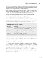
is directly reflecting off of the metal surface. Figure 5.5 illustrates this. The sphere on the
left uses a material such as metal. The illusion of shininess is caused by the bright spot,
known as a specular highlight. The sphere on the right uses a cloth-like material and thus
appears dull.
The shininess of a material is simulated by the size of the specular highlight. This is
controlled via a single scalar value, which you can set using
GL_SHININESS
. This value can
range from 0 to 128, with values of 128 representing an extremely shiny material with a
Lighting in OpenGL 113
Figure 5.5 The effects of
GL_SHININESS
. The sphere on the left has a
shininess of 128; the sphere on the right has a shininess of 0.
05 BOGL_GP CH05 3/1/04 10:16 AM Page 113
TLFeBOOK
small specular highlight, and 0 representing a material that is not shiny at all with a very
large specular highlight.
The following code was used to set up the shininess for the metallic sphere in Figure 5.5.
glMaterialf(GL_FRONT_AND_BACK, GL_SHININESS, 128);
Emissive Materials
The emissive property of materials allows you to cheaply simulate objects that emit light,
such as an area light or anything that glows. It’s important to note that the object won’t
really emit light, so it won’t illuminate nearby objects. The emissive term is simply added
to the other lighting components to cause the object to appear brighter than it normally
would. The emissive term is set using
GL_EMMISION
, as follows:
// use a dark gray color
GLfloat emissiveColor[] = {0.3, 0.3, 0.3, 1.0};
// set the emissive term for both the front and back face
glMaterialfv(GL_FRONT_AND_BACK, GL_EMISSION, emmisiveColor);
This causes the object to appear slightly brighter than it otherwise would. By default, the
emissive term is (0.0, 0.0, 0.0, 1.0);
Color Tracking
Another way to set material properties is by what is called color tracking. Color tracking
allows you to set material properties with calls to the
glColor()
function instead of
using
glMaterial()
, which often allows for more efficient code. You can use color
tracking by passing the
GL_COLOR_MATERIAL
parameter to the
glEnable()
function. Then you
use
glColorMaterial()
function to specify which material parameters will be affected by
calls to
glColor()
. The prototype for
glColorMaterial()
is
void glColorMaterial(GLenum face, GLenum mode);
The
face
parameter can be
GL_FRONT
,
GL_BACK
,or
GL_FRONT_AND_BACK
.The
mode
parameter can
be
GL_AMBIENT
,
GL_DIFFUSE
,
GL_SPECULAR
,
GL_AMBIENT_AND_DIFFUSE
,or
GL_EMISSION
. Most often,
you will use the default values of
GL_FRONT_AND_BACK
and
GL_AMBIENT_AND_DIFFUSE
.
Here is some sample code to set the diffuse property of the fronts of polygons to track the
current color:
glEnable(GL_COLOR_MATERIAL); // enable color tracking
glColorMaterial(GL_FRONT, GL_DIFFUSE); // front of polygons, diffuse material
glColor3f(1.0f, 0.0f, 0.0f); // set color to red
glBegin(GL_TRIANGLES);
// draw triangles
glEnd();
Chapter 5
■
Colors, Lighting, Blending, and Fog114
05 BOGL_GP CH05 3/1/04 10:16 AM Page 114
TLFeBOOK
As you can see, color tracking is very simple to set
up and use.
Normals
Normals are vectors that are perpendicular to a
surface. They are important in lighting because
they can be used to describe the orientation of
that surface. When a light source is specified, it is
either at some specific point in space or shines in
a particular direction. When you draw an object,
the light rays from this light source approach and
strike the surfaces of the object at some angle.
Using the angle between the incoming light ray
and the normal, combined with lighting and
material properties, you can calculate the color of
the surface. This is illustrated in Figure 5.6.
In OpenGL, normals are specified on a per-vertex basis, rather than per-polygon. The
advantage of this is that when you have only one normal per polygon, it assumes that all
points on the polygon have the same orientation. This would be fine for flat surfaces, but
often, a group of small triangles is used to represent curved surfaces. With vertex normals,
each normal can have a slightly different orientation, allowing you to simulate curved sur-
faces. In addition, if you really want a flat surface, you can use the same normal values for
each vertex, so this approach is much more flexible.
OpenGL maintains a current normal in its internal state. Any time you specify a vertex
when lighting is enabled, the current normal is associated with it. You will typically mod-
ify the current normal once per vertex or once per polygon. To change the current nor-
mal, you use the following:
void glNormal3{bsifd}(TYPE nx, TYPE ny, TYPE nz);
void glNormal3{bsifd}v(const TYPE *v);
The values passed to
glNormal()
represent a three-dimensional vector specifying the
normal. The following code specifies a triangle with a normal pointing in the positive y
direction.
glBegin(GL_TRIANGLES);
glNormal3f(0.0, 1.0, 0.0);
glVertex3f(–3.0, 0.0, 2.0);
glVertex3f(2.0, 0.0, 0.0);
glVertex3f(–1.0, 0.0, –3.0);
glEnd();
Lighting in OpenGL 115
Figure 5.6 The surface normal.
05 BOGL_GP CH05 3/1/04 10:16 AM Page 115
TLFeBOOK
As you can see, all three vertices use the same normal. If you wanted to specify a different
normal for each vertex, it would look something like the following:
glBegin(GL_TRIANGLES);
glNormal3f(–0.707f, 0.707f, 0.0);
glVertex3f(–3.0, 0.0, 2.0);
glNormal3f(0.707f, 0.707f, 0.0);
glVertex3f(2.0, 0.0, 0.0);
glNormal3f(0.0, 0.707f, –0.707f);
glVertex3f(–1.0, 0.0, –3.0);
glEnd();
Calculating Normals
Finding the normal for a flat surface is easy. You just need to apply a little vector math—
in particular, the cross product. As a reminder, given two 3D vectors A and B, the cross
product will produce a vector that is perpendicular to both A and B. The equation for cal-
culating the cross product is
A × B = (A
y
B
z
–A
z
B
y
, A
z
B
x
–A
x
B
z
, A
x
B
y
–A
y
B
x
)
This means that you need two vectors, A and B, to calculate your surface’s normal. Where
can you find two vectors? For any triangle, you have three points, P1, P2, and P3. You can
then define two vectors V1 and V2 that go from P1
to P2 and P1 to P3. respectively. Figure 5.7 illustrates
this.
Now all you have to do is take the cross product of
V1 and V2, and you get your normal. Remember
that when taking the cross product, the order of the
vectors matters. V1 × V2 points in the opposite
direction as V2 × V1. When computing the surface
normal this way, you have to be sure that you are
consistent with the vertex winding. So, if you are
using counterclockwise winding, with the vertices
ordered P1, P2, and P3, the vectors should be con-
structed as follows:
V1 = P2–P1
V2 = P3–P1
The normal would then be V1 × V2.
This method is very straightforward, but it works only for a flat shading model where all
of the vertices in a polygon have the same normals. If you are using multiple polygons to
simulate a complex rounded surface, then each normal will be slightly different to vary the
Chapter 5
■
Colors, Lighting, Blending, and Fog116
Figure 5.7 You can define two
vectors,
V1
and
V2,
out of three points.
05 BOGL_GP CH05 3/1/04 10:16 AM Page 116
TLFeBOOK
lighting across the surface. One way to achieve this is to compute the surface normal for
every triangle touching a vertex and then take the average of them, possibly weighting
them based on the area of each triangle. This breaks down when the mesh contains hard
edges. For instance, imagine applying this algorithm to a cube. You’d end up with the cor-
ners looking rounded, which isn’t correct. There are solutions to this, such as using
smoothing groups, which identify groups of triangles to be used together when averaging
normals. Alternatively, you could set a threshold, such that any triangle with a surface nor-
mal more than x degrees different from the current normal is not used in the average.
The Unit Normal and Normalization
Many operations involving vectors can be simplified if you know the vectors have a length
of 1. These are known as unit vectors. If you remember your vector math, given a vector
A, you can find the length using the equation
|A| = sqrt(A
x
2
+ A
y
2
+ A
z
2
)
Unit normals are simply unit vectors that are used as normals. OpenGL assumes that any
normals you pass to it are already of unit length. If you use normals that are not of unit
length, you’ll get strange lighting results. Usually, the normals stored in standard 3D
model formats will already be of unit length. If you’re calculating the normals on the fly,
you’ll have to convert them to unit length yourself. This process is known as normaliza-
tion. Doing so is simply a matter of dividing each component of the normal by the length
of the normal.
An alternative to manually normalizing your normals is to tell OpenGL to do it for you
by enabling
GL_NORMALIZE
, as follows:
glEnable(GL_NORMALIZE);
This approach isn’t terribly efficient. Most of the time, you’ll calculate your normals only
once, so it makes more sense to normalize them at the same time, rather than having
OpenGL repeatedly normalize them every frame.
The main reason OpenGL includes the ability to normalize normals is that the inverse
transposition of the modelview matrix is applied to normals prior to lighting. If the mod-
elview matrix includes scaling, the normals may not be of unit length after this operation.
If you are using scaling, you should definitely enable
GL_NORMALIZE
to ensure that unit nor-
mals are being used in lighting.
If you are using only uniform scaling—in other words, if you are scaling equally in all
three directions—then you can use a potentially cheaper alternative to
GL_NORMALIZE
.
GL_RESCALE_NORMAL
extracts the scale factor from the modelview matrix and uses it to rescale
the normal after the matrix is applied. You enable
GL_RESCALE_NORMAL
as follows:
glEnable(GL_RESCALE_NORMAL);
Lighting in OpenGL 117
05 BOGL_GP CH05 3/1/04 10:16 AM Page 117
TLFeBOOK
Extension
Extension name:
EXT_rescale_normal
Name string:
GL_EXT_rescale_normal
Promoted to core: OpenGL 1.2
Tokens:
GL_RESCALE_NORMAL_EXT
Unlike
GL_NORMALIZE
, which works with normals of any length,
GL_RESCALE_NORMAL
assumes
that the original normals were of unit length.
The Lighting Model
In addition to individual lights and materials, there are additional global components of
the lighting model that the final color values compute by lighting. These are
■
A global ambient term.
■
Whether the location of the viewer is local or infinite (affects specular calculation).
■
Whether lighting is one sided or two sided.
■
Whether the calculated specular color is stored separately from the other color val-
ues and passed on to the rasterization stage.
You control these elements of the lighting model with the
glLightModel()
function, which
is defined as
void glLightModel{if}(GLenum pname, TYPE param);
void glLightModel{if}v(GLenum pname, const TYPE *param);
The first parameter of each of these functions,
pname
, specifies which lighting model prop-
erty you are modifying. The second parameter is the value that you are setting for the
lighting model property. It will be either a single value or an array of values, depending
on the version of the function used. The
pname
parameter can be set to any of the values
listed in Table 5.3.
Chapter 5
■
Colors, Lighting, Blending, and Fog118
Table 5.3 glLightModel*() Parameters
Parameter Name Meaning
GL_LIGHT_MODEL_AMBIENT
Ambient intensity of the scene (RGBA); default value is (0.2, 0.2, 0.2, 1.0).
GL_LIGHT_MODEL_LOCAL_VIEWER
Viewpoint is local or infinite; default value is
GL_FALSE
(infinite).
GL_LIGHT_MODEL_TWO_SIDE
One-sided or two-sided lighting; default value is
GL_FALSE
(one-sided).
GL_LIGHT_MODEL_COLOR_CONTROL
Specular color is stored separate from ambient and diffuse color; default
value is
GL_SINGLE_COLOR
(not separate).
05 BOGL_GP CH05 3/1/04 10:16 AM Page 118
TLFeBOOK