beginning opengl game programming 2004 phần 6 pps
Bạn đang xem bản rút gọn của tài liệu. Xem và tải ngay bản đầy đủ của tài liệu tại đây (804.72 KB, 36 trang )
By default, you have to specify all levels starting from level 0 to the level at which the tex-
ture becomes 1 × 1 (which is equivalent to log
2
of the largest dimension of the base tex-
ture). You can, however, change these limits by using the
glTexParameter()
function with its
pname
parameter set to
GL_TEXTURE_BASE_LEVEL
or
GL_TEXTURE_MAX_LEVEL
, respectively. The
value passed to either of these parameters must be a positive integer.
Mipmapping is first enabled by specifying one of the mipmapping values for texture
minification. Once the texture minification filter has been set, you then only need to spec-
ify the texture mipmap levels with one of the
glTexImage3D()
,
glTexImage2D()
,or
glTexIm-
age1D()
functions, depending on your texture dimensionality. The following example code
sets up a seven-level mipmap with a minification filter of
GL_NEAREST_MIPMAP_LINEAR
and
starting at a 64 × 64 base texture:
glTexParameteri(GL_TEXTURE_2D, GL_TEXTURE_MAG_FILTER, GL_LINEAR);
glTexParameteri(GL_TEXTURE_2D, GL_TEXTURE_MIN_FILTER, GL_NEAREST_MIPMAP_LINEAR);
glTexImage2D(GL_TEXTURE_2D, 0, GL_RGB, 64,64,0, GL_RGB, GL_UNSIGNED_BYTE, texImage0);
glTexImage2D(GL_TEXTURE_2D, 1, GL_RGB, 32,32,0, GL_RGB, GL_UNSIGNED_BYTE, texImage1);
glTexImage2D(GL_TEXTURE_2D, 2, GL_RGB, 16,16,0, GL_RGB, GL_UNSIGNED_BYTE, texImage2);
glTexImage2D(GL_TEXTURE_2D, 3, GL_RGB, 8, 8, 0, GL_RGB, GL_UNSIGNED_BYTE, texImage3);
glTexImage2D(GL_TEXTURE_2D, 4, GL_RGB, 4, 4, 0, GL_RGB, GL_UNSIGNED_BYTE, texImage4);
glTexImage2D(GL_TEXTURE_2D, 5, GL_RGB, 2, 2, 0, GL_RGB, GL_UNSIGNED_BYTE, texImage5);
glTexImage2D(GL_TEXTURE_2D, 6, GL_RGB, 1, 1, 0, GL_RGB, GL_UNSIGNED_BYTE, texImage6);
Mipmaps and the OpenGL Utility Library
The GLU library provides the
gluBuild2DMipmaps()
and
gluBuild1DMipmaps()
functions to
build mipmaps automatically for two- and one-dimensional textures, respectively. These
Mipmaps 167
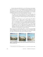
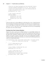
Figure 7.6 Mipmaps help control the level of detail for textured objects.
07 BOGL_GP CH07 3/1/04 10:03 AM Page 167
TLFeBOOK
functions replace the set of function calls you would normally make to the
glTexImage2D()
and
glTexImage1D()
functions to specify mipmaps.
int gluBuild2DMipmaps(GLenum target, GLint components, GLint width, GLint height,
GLenum format, GLenum type, const void *data);
int gluBuild1DMipmaps(GLenum target, GLint components GLint width, GLenum format,
GLenum type, const void *data);
One of the nice features about these functions is that you do not have to pass a power-of-
2 image because
gluBuild2DMipmaps()
and
gluBuild1DMipmaps()
automatically rescale your
images’ width and height to the closest power of 2 for you.
The following code uses the
gluBuild2DMipmaps()
function to specify mipmaps in the same
way as the previous mipmap example using
glTexImage2D()
:
glTexParameteri(GL_TEXTURE_2D, GL_TEXTURE_MAG_FILTER, GL_LINEAR);
glTexParameteri(GL_TEXTURE_2D, GL_TEXTURE_MIN_FILTER, GL_NEAREST_MIPMAP_LINEAR);
gluBuild2DMipmaps(GL_TEXTURE_2D, GL_RGB, 64, 64, GL_RGB, GL_UNSIGNED_BYTE, texImage0);
Automatic Mipmap Generation
Extension
Extension name:
SGIS_generate_mipmap
Name string:
GL_SGIS_generate_mipmap
Promoted to core: OpenGL 1.4
Function names: None
Tokens:
GL_GENERATE_MIPMAP_SGIS
As of Version 1.4, OpenGL has introduced a new method for automatically generating
mipmaps with the texture parameter
GL_GENERATE_MIPMAP
. Setting this parameter to
GL_TRUE
will induce a mechanism that automatically generates all mipmap levels higher than the
base level. The internal formats and border widths of the derived mipmap images all
match those of the base level image, and each increasing mipmap level reduces the size of
the image by half. The actual contents of the mipmap images are computed by a repeated,
filtered reduction of the base mipmap level.
One of the nice features of this parameter is that if you change the texture image data, the
mipmap data is calculated automatically, which makes it extremely useful for textures
you’re changing on the fly.
We are actually discussing texture parameters in the next section. This means you should
read on to find out how to use the automatic mipmap generation functionality of
OpenGL!
Chapter 7
■
Texture Mapping168
07 BOGL_GP CH07 3/1/04 10:03 AM Page 168
TLFeBOOK
Texture Parameters
OpenGL provides several parameters to control how textures are treated when specified,
changed, or applied as texture maps. Each parameter is set by calling the
glTexParameter()
function (as mentioned in the section “Texture Filtering”):
void glTexParameter{if}(GLenum target, GLenum pname, TYPE param);
void glTexParameter{if}v(GLenum target, GLenum pname, TYPE params);
As mentioned before, the value of the
target
parameter refers to the texture target and can
be equal to
GL_TEXTURE_1D
,
GL_TEXTURE_2D
,
GL_TEXTURE_3D
,or
GL_TEXTURE_CUBE_MAP
.The
pname
parameter is a constant indicating the parameter to be set, a list of which is shown in Table
7.5. In the first form of the
glTexParameter()
function,
param
is a single-valued parameter;
in the second form,
params
is an array of parameters whose type depends on the parame-
ter being set.
Texture Parameters 169
Table 7.5 Texture Parameters
Name Type Values
GL_TEXTURE_WRAP_S
integer
GL_CLAMP
,
GL_CLAMP_TO_EDGE
*,
GL_REPEAT
,
GL_CLAMP_TO_BORDER
*,
GL_MIRRORED_REPEAT
*
GL_TEXTURE_WRAP_T
integer
GL_CLAMP
,
GL_CLAMP_TO_EDGE
*,
GL_REPEAT
,
GL_CLAMP_TO_BORDER
*,
GL_MIRRORED_REPEAT
*
GL_TEXTURE_WRAP_R
integer
GL_CLAMP
,
GL_CLAMP_TO_EDGE
*,
GL_REPEAT
,
GL_CLAMP_TO_BORDER
*,
GL_MIRRORED_REPEAT
*
GL_TEXTURE_MIN_FILTER
integer
GL_NEAREST
,
GL_LINEAR
,
GL_NEAREST_MIPMAP_NEAREST
,
GL_NEAREST_MIPMAP_LINEAR
,
GL_LINEAR_MIPMAP_NEAREST
,
GL_LINEAR_MIPMAP_LINEAR
GL_TEXTURE_MAG_FILTER
integer
GL_NEAREST, GL_LINEAR
GL_TEXTURE_BORDER_COLOR
4 floats any 4 values from 0 to 1
GL_TEXTURE_PRIORITY
float any value from 0 to 1
GL_TEXTURE_MIN_LOD
* float any value
GL_TEXTURE_MAX_LOD
* float any value
GL_TEXTURE_BASE_LEVEL
* integer any non-negative integer
GL_TEXTURE_MAX_LEVEL
* integer any non-negative integer
GL_TEXTURE_LOD_BIAS
* float any value
GL_DEPTH_TEXTURE_MODE
** enum
GL_LUMINANCE
,
GL_INTENSITY
,
GL_ALPHA
GL_TEXTURE_COMPARE_MODE
** enum
GL_NONE
,
GL_COMPARE_R_TO_TEXTURE
GL_TEXTURE_COMPARE_FUNC
** enum
GL_LEQUAL
,
GL_GEQUAL
,
GL_LESS
,
GL_GREATER
,
GL_EQUAL
,
GL_NOTEQUAL
,
GL_ALWAYS
,
GL_NEVER
GL_GENERATE_MIPMAP
* boolean
GL_TRUE
or
GL_FALSE
* Available only via extensions under Windows. See the explanation of the parameter in this chapter for details.
** Available only via the
ARB_depth_texture
and
ARB_shadow
extensions under Windows.
07 BOGL_GP CH07 3/1/04 10:03 AM Page 169
TLFeBOOK
Texture parameters for a cube map texture apply to the entire cube map; the six individ-
ual texture images cannot be controlled separately.
Texture Wrap Modes
Texture wrap modes allow you to modify how OpenGL interprets texture coordinates
outside of the range [0, 1] and at the edge of textures. Using the
glTexParameter()
function
with
GL_TEXTURE_WRAP_S
,
GL_TEXTURE_WRAP_T
,or
GL_TEXTURE_WRAP_R
, you can specify how
OpenGL interprets the s, t, and r texture coordinates, respectively.
OpenGL provides five wrap modes:
GL_REPEAT, GL_CLAMP
,
GL_CLAMP_TO_EDGE
,
GL_CLAMP_TO_BOR-
DER
, and
GL_MIRRORED_REPEAT
. Let’s discuss these individually.
Wrap Mode GL_REPEAT
The
GL_REPEAT
wrap mode is the default behavior of OpenGL for texture coordinates. In
this mode, OpenGL essentially ignores the integer portion of texture coordinates and uses
only the fractional part. For example, if you specify the 2D texture coordinates (2.0, 2.0),
then the texture will be placed twice in the s and t directions, as compared to the texture
being placed once with texture coordinates of (1.0, 1.0) in the same polygon space. This
essentially means
GL_REPEAT
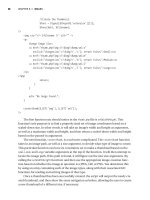
allows you to create a tiled effect. Figure 7.7 illustrates how the
GL_REPEAT
wrap mode with texture coordinates (2.0, 2.0) affects the TextureBasics example
presented earlier.
Chapter 7
■
Texture Mapping170
Figure 7.7 Result of using
GL_REPEAT
with texture coordinates (2.0, 2.0)
with the TextureBasics example.
07 BOGL_GP CH07 3/1/04 10:03 AM Page 170
TLFeBOOK
While
GL_REPEAT
is OpenGL’s default behavior, you can force it by specifying
GL_REPEAT
as
the value for
GL_TEXTURE_WRAP_S
,
GL_TEXTURE_WRAP_T
,or
GL_TEXTURE_WRAP_R
. The following line
of code will force
GL_REPEAT
on the currently bound texture object’s s coordinate:
glTexParameteri(GL_TEXTURE_2D, GL_TEXTURE_WRAP_S, GL_REPEAT);
Wrap Mode GL_CLAMP
The
GL_CLAMP
wrap mode simply clamps texture coordinates in the range 0.0 to 1.0. If you
specify texture coordinates outside this range, then OpenGL will take the edge of the tex-
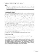
ture and extend it to the remainder of the textured surface. Figure 7.8 illustrates how the
GL_CLAMP
wrap mode with texture coordinates (2.0, 2.0) affects the TextureBasics example
presented earlier (look at the right polygon).
The following example line of code tells OpenGL to use
GL_CLAMP
on the currently bound
texture object’s t coordinate:
glTexParameteri(GL_TEXTURE_2D, GL_TEXTURE_WRAP_T, GL_CLAMP);
Texture Parameters 171
Figure 7.8 Result of using
GL_CLAMP
with texture coordinates (2.0, 2.0)
in the TextureBasics example.
07 BOGL_GP CH07 3/1/04 10:03 AM Page 171
TLFeBOOK
Wrap Mode GL_CLAMP_TO_EDGE
The
GL_CLAMP_TO_EDGE
wrap mode clamps texture coordinates such that the texture filter
never samples a border texel. Normally, OpenGL clamps such that the texture coordinates
are limited to exactly the range 0 to 1. This means that when
GL_CLAMP
is used, OpenGL
straddles the edge of the texture image, taking half of its color sample values from within
the texture image and the other half from the texture border.
When
GL_CLAMP_TO_EDGE
is used, however, OpenGL never takes color samples from the tex-
ture border. The color used for clamping is taken only from the texels at the edge of the
texture image. This can be used to prevent seams between textures.
The following line of code tells OpenGL to use
GL_CLAMP_TO_EDGE
on the currently bound
texture object’s s coordinate:
glTexParameteri(GL_TEXTURE_2D, GL_TEXTURE_WRAP_S, GL_CLAMP_TO_EDGE);
Extension
Extension name:
SGIS_texture_edge_clamp
Name string:
GL_SGIS_texture_edge_clamp
Promoted to core: OpenGL 1.2
Function names: None
Tokens:
GL_CLAMP_TO_EDGE_SGIS
Wrap Mode GL_CLAMP_TO_BORDER
The
GL_CLAMP_TO_BORDER
wrap mode clamps texture coordinates in such a way that mirrors
the behavior of
GL_CLAMP_TO_EDGE
. Instead of sampling only the edge of the texture image,
GL_CLAMP_TO_BORDER
only samples the texture border for its clamp color.
The following line of code tells OpenGL to use
GL_CLAMP_TO_BORDER
on the currently bound
texture object’s s coordinate:
glTexParameteri(GL_TEXTURE_2D, GL_TEXTURE_WRAP_S, GL_CLAMP_TO_BORDER);
Extension
Extension name:
ARB_texture_border_clamp
Name string:
GL_ARB_texture_border_clamp
Promoted to core: OpenGL 1.3
Function names: None
Tokens:
GL_CLAMP_TO_BORDER_ARB
Chapter 7
■
Texture Mapping172
07 BOGL_GP CH07 3/1/04 10:03 AM Page 172
TLFeBOOK
Wrap Mode GL_MIRRORED_REPEAT
The
GL_MIRRORED_REPEAT
wrap mode essentially defines a texture map twice as large as the
original texture image. The additional texture map area created contains a mirror image
of the original texture. You can use this wrap mode to achieve seamless tiling of a surface.
The following line of code tells OpenGL to use
GL_MIRRORED_REPEAT
on the currently bound
texture object’s s coordinate:
glTexParameteri(GL_TEXTURE_2D, GL_TEXTURE_WRAP_S, GL_MIRRORED_REPEAT);
Extension
Extension name:
ARB_texture_mirrored_repeat
Name string:
GL_ARB_texture_mirrored_repeat
Promoted to core: OpenGL 1.4
Function names: None
Tokens:
GL_MIRRORED_REPEAT_ARB
Texture Level of Detail
The decision to use the minification filtering mode or the magnification filtering mode on
a texture is determined by a set of parameters controlling the texture level of detail calcu-
lations. By manipulating these parameters, you can control the transition of textures from
minification filtering to magnification filtering and vice versa.
Two of these parameters,
GL_TEXTURE_MIN_LOD
and
GL_TEXTURE_MAX_LOD
, allow you to control
the level of detail range. By default, the range is [–1000.0, 1000.0], which essentially guar-
antees that the level of detail will never be clamped. The following code sets the level of
detail range to [–10.0, 10.0] for a two-dimensional texture:
glTexParameterf(GL_TEXTURE_2D, GL_TEXTURE_MIN_LOD, -10.0);
glTexParameterf(GL_TEXTURE_2D, GL_TEXTURE_MAX_LOD, 10.0);
Another parameter,
GL_TEXTURE_LOD_BIAS
, allows you to control the level of detail bias level,
causing it to change levels sooner or later than it normally would. The bias level is used in
the computation for determining the mipmap level of detail selection, providing a means
to blur or sharpen textures. This functionality can lead to special effects such as depth of
field, blurring, or image processing. Here’s an example:
glTexParameterf(GL_TEXTURE_2D, GL_TEXTURE_LOD_BIAS, 3.0);
Texture Parameters 173
07 BOGL_GP CH07 3/1/04 10:03 AM Page 173
TLFeBOOK
Extension
Extension name:
EXT_texture_lod_bias
Name string:
GL_EXT_texture_lod_bias
Promoted to core: OpenGL 1.4
Function names: None
Tokens:
GL_TEXTURE_LOD_BIAS_EXT
Texture Environments and Texture Functions
OpenGL’s
glTexEnv()
function allows you to set parameters of the texture environment
that determine how texture values are applied when texturing:
void glTexEnv{if}(GLenum target, GLenum pname, T param);
void glTexEnv{if}v(GLenum target, GLenum pname, T params);
For this function, the
target
parameter must be either
GL_TEXTURE_ENV
or
GL_TEXTURE_
FILTER_CONTROL
.The
pname
parameter tells OpenGL which parameter you wish to set with
the value passed to
param
(or
params
for an array of values).
To better explain the purpose of texture environments, let’s review how OpenGL textur-
ing works. Texturing is enabled and disabled with the
glEnable()
/
glDisable()
functions by
specifying the dimensionality of the texture you wish to use. For instance, you may spec-
ify
GL_TEXTURE_1D
,
GL_TEXTURE_2D
,
GL_TEXTURE_3D
,or
GL_TEXTURE_CUBE_MAP
to enable the one-,
two-, or three-dimensional, or cube map texture mapping, respectively. The rule of tex-
ture dimensionality follows that the highest enabled dimensionality (1D, 2D, 3D, cube) is
enabled and used for texture mapping. If all texturing is disabled, any fragments coming
through the pipeline are simply passed to the next stage.
If texturing is enabled, a texture is determined based on the texture parameters and
dimensionality (1D, 2D, 3D, or cube map) of the incoming fragment. The texture envi-
ronment is then used to determine the texture function applied to the texture, whose red,
green, blue, and alpha values are then replaced with freshly computed ones. These RGBA
values are finally passed on to further OpenGL operations in the pipeline.
OpenGL includes one or more texture units representing stages in the texture mapping
process that are enabled and have texture objects bindings independently from each other.
Each unit has its own set of states, including those related to the texture environment.
Figure 7.9 illustrates how each texture unit is paired with a texture environment function.
Note that in the figure each texture unit passes its results on to the next texture unit. This
Chapter 7
■
Texture Mapping174
07 BOGL_GP CH07 3/1/04 10:03 AM Page 174
TLFeBOOK
functionality is called multitexturing, which will be discussed in Chapter 9, “More on Tex-
ture Mapping.” Only the first texture unit (typically texture unit zero) is used when using
basic texture mapping techniques as described in this chapter. The important concept to
understand right now is that a texture environment is tied to a texture unit and affects all
textures passing through that texture unit. This is contrary to the common misconception
among newcomers to OpenGL that each texture object maintains states related to the tex-
ture environment.
Now that we have that down, let’s discuss how we modify the texture environment.
Specifying the Texture Environment
Looking back at the
glTexEnv()
function, if the
target
is equal to
GL_TEXTURE_FILTER_CONTROL
,
then
pname
must be set equal to
GL_TEXTURE_LOD_BIAS
. The value parameter passed must then
be a single floating-point value that sets the level of detail bias for the currently active tex-
ture unit. This functionality is equivalent to the texture object level of detail bias described
in the section “Texture Level of Detail” in this chapter.
When
target
is equal to
GL_TEXTURE_ENV
,
pname
can be set to
GL_TEXTURE_ENV_MODE
,
GL_TEXTURE_ENV_COLOR
,
GL_COMBINE_RGB
,or
GL_COMBINE_ALPHA
.
If
GL_TEXTURE_ENV_COLOR
is used, then OpenGL expects four floating-point values in the
range from 0 to 1 representing an RGBA color to be passed to the
params
parameter. You
may also pass four integers, and OpenGL will convert them to floating-point values as
necessary. This color is used in conjunction with the
GL_BLEND
environment mode.
Texture Environments and Texture Functions 175
Figure 7.9 Texture environments operate on all textures passed through their
associated texture units.
07 BOGL_GP CH07 3/1/04 10:03 AM Page 175
TLFeBOOK
If
pname
is
GL_TEXTURE_ENV_MODE
, then you
are specifying the texture function.The
result of a texture function is dependent
on the texture itself and the fragment it is
being applied to. The exact texture func-
tion that is used depends on the internal
format of the texture that was specified.
For reference, the base internal formats
are listed in Table 7.6. Acceptable values
for
GL_TEXTURE_ENV_MODE
are
GL_REPLACE
,
GL_MODULATE
,
GL_DECAL
,
GL_BLEND
,
GL_ADD
, and
GL_COMBINE
.
Note
You may notice subscripts being used in the following tables. A subscript of
t
indicates a filtered
texture value,
s
indicates the texture source color,
f
denotes the incoming fragment value,
c
refers
to the values assigned with
GL_TEXTURE_ENV_COLOR
, and
v
refers to the final computed value. For
regular-sized text,
C
refers to the RGB triplet,
A
is the alpha component value,
L
is a luminance
component value, and
I
is an intensity component value.
The color values listed in the following tables are all in the range [0, 1]. Each table shows
how the texture functions use colors from the texture value, texture source color, incom-
ing fragment color, and texture environment value to determine the final computed value.
Table 7.7 includes the calculations for
GL_REPLACE
,
GL_MODULATE
, and
GL_DECAL
. Table 7.8
includes the calculations for
GL_BLEND
and
GL_ADD
.
Chapter 7
■
Texture Mapping176
Table 7.6 Texture Internal Formats
Format Texture Source Color
GL_ALPHA
C
s
= (0, 0, 0); A
s
= A
t
GL_LUMINANCE
C
s
= (L
t
,L
t
,L
t
); A
s
= 1
GL_LUMINANCE_ALPHA
C
s
= (L
t
,L
t
,L
t
); A
s
= A
t
GL_INTENSITY
C
s
= (I
t
,I
t
,I
t
); A
s
= I
t
GL_RGB
C
s
= (R
t
,G
t
,B
t
); A
s
= 1
GL_RGBA
C
s
= (R
t
,G
t
,B
t
); A
s
= A
t
Table 7.7 GL_REPLACE, GL_MODULATE, GL_DECAL
Format GL_REPLACE GL_MODULATE GL_DECAL
GL_ALPHA
C
v
= C
f
C
v
= C
f
undefined
A
v
= A
s
A
v
= A
f
A
s
GL_LUMINANCE
C
v
= C
s
C
v
= C
f
C
s
undefined
A
v
= A
s
A
v
= A
f
GL_LUMINANCE_ALPHA
C
v
= C
s
C
v
= C
f
C
s
undefined
A
v
= A
s
A
v
= A
f
A
s
GL_INTENSITY
C
v
= C
s
C
v
= C
f
C
s
undefined
A
v
= A
s
A
v
= A
f
A
s
GL_RGB
C
v
= C
s
C
v
= C
f
C
s
C
v
= C
s
A
v
= A
f
A
v
= A
f
A
v
= A
f
GL_RGBA
C
v
= C
s
C
v
= C
f
C
s
C
v
= C
f
(1 - A
s
) + C
s
A
s
A
v
= A
s
A
v
= A
f
A
s
A
v
= A
f
07 BOGL_GP CH07 3/1/04 10:03 AM Page 176
TLFeBOOK
Since we know these tables can be a little overwhelming for the uninitiated, let’s step
through a couple of these formulas and figure out what exactly is going on. We’ll start with
one of the easy ones and look at
GL_REPLACE
with the format
GL_RGBA
.
Looking at the table, you will see C
v
= C
s
and A
v
= A
s
. That’s not too bad, right? But what
is it saying? As noted prior to the tables, the s subscript indicates the texture source color,
and the v subscript indicates our final color output. So, C
v
= C
s
says that the texture source
RGB values will be transferred straight to the final color output. Similarly, A
v
= A
s
says
that the alpha component will be copied to the final alpha output value. So if we have an
RGBA color value of (0.5, 0.3, 0.8, 0.5), then the final RGBA output value will be (0.5, 0.3,
0.8, 0.5). How about a slightly more difficult equation, like
GL_MODULATE
on the
GL_RGBA
format?
In the table you will see C
v
= C
f
C
s
and A
v
= A
f
A
s
. It’s not a terribly complicated set of func-
tions, but the results are much different. So, what are these equations saying? Well, you
know what the s and v subscript are, and if you look at the prior note you will see that the
f subscript denotes the incoming fragment value. C
v
= C
f
C
s
is saying that the fragment
color is multiplied by the texture source color. A
v
= A
f
A
s
is saying the same, except with
the alpha component values. As an example, these formulas are saying that if the polygon
we are texturing has a solid color of red without transparency, (1.0, 0.0, 0.0, 1.0), and we
reach a texture color value of (0.2, 1.0, 0.7, 0.5), then the final color output for the texture
fragment will be equal to (1.0 × 0.2, 0.0 × 1.0, 0.0 × 0.7, 1.0 × 0.5), or (0.2, 0.0, 0.0, 0.5).
That’s not too bad, right? One more example:
GL_BLEND
with
GL_RGB
.
Texture Environments and Texture Functions 177
Table 7.8 GL_BLEND and GL_ADD
Format GL_BLEND GL_ADD*
GL_ALPHA
C
v
= C
f
C
v
= C
f
A
v
= A
f
A
s
A
v
= A
f
A
s
GL_LUMINANCE
C
v
= C
f
(1 - C
s
) + C
c
C
s
C
v
= C
f
+ C
s
A
v
= A
f
A
v
= A
f
GL_LUMINANCE_ALPHA
C
v
= C
f
(1 - C
s
) + C
c
C
s
C
v
= C
f
+ C
s
A
v
= A
f
A
s
A
v
= A
f
A
s
GL_INTENSITY
C
v
= C
f
(1 - C
s
) + C
c
C
s
C
v
= C
f
+ C
s
A
v
= A
f
(1 - A
s
) + A
c
A
s
A
v
= A
f
A
s
GL_RGB
C
v
= C
f
(1 - C
s
) + C
c
C
s
C
v
= C
f
+ C
s
A
v
= A
f
A
v
= A
f
GL_RGBA
C
v
= C
f
(1 - C
s
) + C
c
C
s
C
v
= C
f
+ C
s
A
v
= A
f
A
s
A
v
= A
f
A
s
* Available only via the
ARB_texture_env_add
extension under Windows.
07 BOGL_GP CH07 3/1/04 10:03 AM Page 177
TLFeBOOK
GL_RGB
doesn’t work with an alpha component value, so we can focus on the equation given
in the table for the RGB values: C
v
= C
f
(1 - C
s
) + C
c
C
s
. In English (or at least our best dialect
of the language), this means that the final color value is equal to the incoming fragment
color multiplied by the result of one minus the texture source color. The result of this mul-
tiplication is then added to the result of the texture environment color multiplied by the tex-
ture source color. In other words, given a texture source color of (0.2, 0.5, 1.0), a fragment
color of (1.0, 0.5, 0.8), and a texture environment color of (0.3, 0.4, 0.9), the formula gives
a final value of (1.4, 0.45, 0.9). However, 1.4 is beyond the [0, 1] range that color values are
limited to, so OpenGL clamps the final color value to (1.0, 0.45, 0.9).
If the value of
GL_TEXTURE_ENV_MODE
is
GL_COMBINE
, then the texture function OpenGL selects
depends on the values of
GL_COMBINE_RGB
and
GL_COMBINE_ALPHA
. This is directly related to
multitexturing, it will be covered in Chapter 9.
Textured Terrain
In OpenGL Game Programming, we provided an example in the texture chapter that ren-
dered and textured a simple heightfield terrain. We are going to revisit that example and
hopefully make it better!
In its most basic form, a heightfield terrain is a virtual representation of a landscape whose
data points are a two-dimensional set of evenly spaced height values. When you render
these data points as a mesh on the screen, you see what resembles a landscape.
Keep in mind that the method we are about to show you is only one way to develop a sim-
ple landscape. Terrain rendering is a fairly large area of computer graphics, with plenty of
research and interest. Do a search for the topic on your favorite search engine, and you
will find enough information to keep you busy for years.
Building the Mesh
Keeping in mind our definition of heightfield terrain, you are going to create a grid of ver-
tices that are spaced evenly apart but have varying height values based on the height of the
terrain data at each vertex’s grid location.
You will be determining the height values by loading a 32 × 32 grayscale Targa image into
memory with each color value in the image representing a height value mapped to a grid
location in the heightfield. Since we will be using a grayscale image, the color values and
effectively the height values will range from 0 to 255.
After loading the height values into an array in memory, you will have a set of data points
that represent the height of the terrain. Next you need to determine the distance between
each height vertex, which we will call the map scale. We will use the map scale to program-
matically increase or decrease the actual width and height of the terrain in world units.
Chapter 7
■
Texture Mapping178
07 BOGL_GP CH07 3/1/04 10:03 AM Page 178
TLFeBOOK
When you assign the 3D vertex coordinates for each height value, you will need to multi-
ply the map scale factor by the height value’s (x, y) index location in the heightfield array.
For example, when you are defining the x coordinate for a vertex, you will determine the
height value’s x-axis location in the heightfield array and multiply that value by the map
scale factor.
To render the terrain map, you will use a
GL_TRIANGLE_STRIP
for each row of height val-
ues along the z-axis. You will need to render
the points of the triangle strip in a specific
order so the heightfield terrain is rendered
properly. Each row is drawn by specifying ver-
tices in a Z pattern along the x-axis, as shown
in Figure 7.10. For texturing, you will texture
every group of 16 vertices. Once you reach the
end of the row, you move on to the next row
of heightfield data and repeat the process
until the terrain is complete. As an added
bonus, water is added into the terrain by ren-
dering a textured quadrilateral at a “water
level” height.
This example also includes a skybox, which is a large cube whose inside faces are textured
with images representing the distant horizon. Skyboxes provide a good, simple way to
enhance the environment of an outdoor graphics scene. The position of the camera is
used as the origin of the skybox, with all six sides of the skybox remaining centered
around the camera even as it moves around the world. Maintaining the origin of the sky-
box at the camera position helps keep the illusion of distance for the viewer.
Finally, we added mouse input control for the camera, so you can rotate and set the height
of the camera with the mouse.
You can see the source code in the CD included with this book, under Chapter 7, and the
folder Terrain. We aren’t going to dump all of the code here for you, but let’s take a look
at the most important function,
DrawTerrain()
:
void CGfxOpenGL::DrawTerrain()
{
// draw the terrain
glBindTexture(GL_TEXTURE_2D, m_grassTexture);
glTexEnvf(GL_TEXTURE_ENV, GL_TEXTURE_ENV_MODE, GL_MODULATE);
for (int z = 0; z < TERRAIN_SIZE - 1; ++z)
{
glBegin(GL_TRIANGLE_STRIP);
Textured Terrain 179
Figure 7.10 Process the vertices in a
Z
pattern for each row in the terrain.
07 BOGL_GP CH07 3/1/04 10:03 AM Page 179
TLFeBOOK
for (int x = 0; x < TERRAIN_SIZE; ++x)
{
// render two vertices of the strip at once
float scaledHeight = heightmap[z * TERRAIN_SIZE + x] / SCALE_FACTOR;
float nextScaledHeight = heightmap[(z + 1)* TERRAIN_SIZE + x] / SCALE_FACTOR;
float color = 0.5f + 0.5f * scaledHeight / MAX_HEIGHT;
float nextColor = 0.5f + 0.5f * nextScaledHeight / MAX_HEIGHT;
glColor3f(color, color, color);
glTexCoord2f((GLfloat)x/TERRAIN_SIZE*8, (GLfloat)z/TERRAIN_SIZE*8);
glVertex3f(static_cast<GLfloat>(x - TERRAIN_SIZE/2), scaledHeight,
static_cast<GLfloat>(z - TERRAIN_SIZE/2));
glColor3f(nextColor, nextColor, nextColor);
glTexCoord2f((GLfloat)x/TERRAIN_SIZE*8, (GLfloat)(z+1)/TERRAIN_SIZE*8);
glVertex3f(static_cast<GLfloat>(x - TERRAIN_SIZE/2), nextScaledHeight,
static_cast<GLfloat>(z + 1 - TERRAIN_SIZE/2));
}
glEnd();
}
//draw the water
glBindTexture(GL_TEXTURE_2D, m_waterTexture);
glTexEnvf(GL_TEXTURE_ENV, GL_TEXTURE_ENV_MODE, GL_REPLACE);
glBegin(GL_QUADS);
glTexCoord2f(0.0, 0.0);
glVertex3f(-TERRAIN_SIZE/2.1f, WATER_HEIGHT, TERRAIN_SIZE/2.1f);
glTexCoord2f(TERRAIN_SIZE/4.0f, 0.0);
glVertex3f(TERRAIN_SIZE/2.1f, WATER_HEIGHT, TERRAIN_SIZE/2.1f);
glTexCoord2f(TERRAIN_SIZE/4.0f, TERRAIN_SIZE/4.0f);
glVertex3f(TERRAIN_SIZE/2.1f, WATER_HEIGHT, -TERRAIN_SIZE/2.1f);
glTexCoord2f(0.0, TERRAIN_SIZE/4.0f);
glVertex3f(-TERRAIN_SIZE/2.1f, WATER_HEIGHT, -TERRAIN_SIZE/2.1f);
glEnd();
}
The first half of the
DrawTerrain()
method draws the actual terrain. First we bind the ter-
rain’s grass texture, and then we loop through every row in the terrain heightfield data and
draw each row two vertices at a time for the
GL_TRIANGLE_STRIP
. We also apply a color to the
terrain based on the height of each vertex as a simple way to make the terrain shaded.
Chapter 7
■
Texture Mapping180
07 BOGL_GP CH07 3/1/04 10:03 AM Page 180
TLFeBOOK
Notice how we use the texture function
GL_MODULATE
to allow the shading color we apply to
mix in with the texture colors.
The second half of the
DrawTerrain()
method draws the water level. The water texture is
bound, and the texture function
GL_REPLACE
is used.
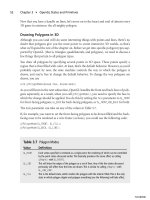
A screenshot of the Terrain example is shown in Figure 7.11.
Summary
In this chapter you learned the basics of texture mapping, including texture objects, how
to specify textures (1D, 2D, 3D, and cube maps), how to use texture coordinates, and how
to set up texture filtering modes. You also learned the concept of mipmaps and how to
create them with OpenGL. And finally you learned about texture parameters and texture
environments and how they affect the final output of your OpenGL texturing.
What You Have Learned
■
Texture mapping allows you to attach images to polygons to create realistic objects.
■
Texture maps are composed of rectangular arrays of data; each element of these
arrays is called a texel.
■
Texture coordinates are used to map textures onto primitives.
■
Texture objects represent texture data and parameters and are accessed through
unique unsigned integers.
Summary 181
Figure 7.11 A screenshot of the Terrain example.
07 BOGL_GP CH07 3/1/04 10:03 AM Page 181
TLFeBOOK
■
Each texture object has a state associated with it that is unique to that texture.
■
The first time you bind a texture, the texture object acquires a new state with ini-
tial values, which you can then modify to suit your needs. After that, binding effec-
tively selects the texture.
■
OpenGL provides three main functions for specifying a texture:
glTexImage1D()
,
glTexImage2D()
, and
glTexImage3D()
.
■
Texture filtering tells OpenGL how it should map the pixels and texels when calcu-
lating the final image.
■
Magnification refers to when a screen pixel represents a small portion of a texel.
■
Minification refers to when a pixel represents a collection of texels.
■
A mipmap is a texture consisting of levels of varying resolutions taken from the
same texture image. Each level in the texture has a resolution lower than the previ-
ous one.
■
OpenGL provides several parameters to control how textures are treated when
specified, changed, or applied as texture maps. Each parameter is set by calling the
glTexParameter()
function.
■
The decision to use the minification filtering mode or the magnification filtering
mode on a texture is determined by a set of parameters controlling the texture
level of detail calculations.
■
OpenGL’s
glTexEnv()
function allows you to set parameters of the texture environ-
ment that determines how texture values are interpreted when texturing.
Review Questions
1. How is 2D texturing enabled in OpenGL?
2. What is a texture object?
3. Write the line of code to specify a 64 × 64 2D RGBA texture whose pixel data is
stored in unsigned bytes.
4. If the base texture level size is 128 × 128, what are the dimensions of the mipmaps?
5. What is the default OpenGL texture wrap mode?
6. True or false: Each texture unit maintains its own texture environment.
On Your Own
1. Given a pointer to 2D image data,
imageData
, whose dimensions are 256 × 256 and
type is RGBA, write code to create a texture object, specify the 2D texture with
mipmaps, and texture a polygon with that texture.
2. Modify the Terrain example to texture the higher elevations of the terrain with a
snow texture.
Chapter 7
■
Texture Mapping182
07 BOGL_GP CH07 3/1/04 10:03 AM Page 182
TLFeBOOK
Beyond
the Basics
Chapter 8
OpenGL Extensions . . . . . . . . . . . . . . . . . . . . . . . . . . . . . . . . . . . . . . . 185
Chapter 9
More on Texture Mapping . . . . . . . . . . . . . . . . . . . . . . . . . . . . . . . . . 197
Chapter 10
Up Your Performance . . . . . . . . . . . . . . . . . . . . . . . . . . . . . . . . . . . . . 221
Chapter 11
Displaying Text . . . . . . . . . . . . . . . . . . . . . . . . . . . . . . . . . . . . . . . . . . 249
Chapter 12
OpenGL Buffers . . . . . . . . . . . . . . . . . . . . . . . . . . . . . . . . . . . . . . . . . . 261
Chapter 13
The Endgame. . . . . . . . . . . . . . . . . . . . . . . . . . . . . . . . . . . . . . . . . . . . 277
PART II
08 BOGL_GP CH08 3/1/04 10:03 AM Page 183
TLFeBOOK
This page intentionally left blank
TLFeBOOK
185
OpenGL Extensions
chapter 8
B
ack in Chapter 1, “The Exploration Begins . . . Again,” we mentioned that the
OpenGL extension mechanism exists so that hardware vendors can easily inno-
vate and add features that graphics and game developers can immediately access
through OpenGL. The most useful and ubiquitous of these extensions eventually become
part of the OpenGL core specification.
In this chapter you’ll learn more about extensions and how to use them. Specifically, you’ll
learn:
■
Exactly what an extension is
■
Why extensions are particularly important on Windows platforms
■
How to use extensions under Windows
■
How to use GLee to manage extensions easily and quickly
Anatomy of an Extension
Fundamentally, an extension is—just like OpenGL itself—a specification. When a new
extension is created, it is documented and released through several channels, most impor-
tantly the official OpenGL Extension Registry, which can be found online at:
/>The specification for an extension includes a great deal of information about the exten-
sion, including a brief justification for its existence, other extensions it depends on or
interacts with, updates to the OpenGL specification that need to be made to accommo-
date it, and a revision history. It also includes the name of the extension, the extension
name string, and new functions and tokens introduced by the extension. Because these are
the things you’ll be dealing with most often, let’s look at each one of them in detail.
08 BOGL_GP CH08 3/1/04 10:03 AM Page 185
TLFeBOOK
Extension Names
Every OpenGL extension has a name by which it can be precisely and uniquely identified.
They use the following naming convention:
PREFIX_extension_name
The
PREFIX
identifies the vendor who developed the extension or, in the case of EXT and
ARB, the extension’s level of promotion. Table 8.1 lists the most important prefixes cur-
rently in use and their associated meaning. The
extension_name
identifies the extension.
Note that the name cannot contain any spaces. Some example extension names are
ARB_shading_language_100
,
EXT_packed_pixels
,
NV_blend_square
, and
ATI_texture_float
.
Tip
Some extensions share a name but have a different prefix. These extensions may not be inter-
changeable because their semantics may differ slightly. For example,
ARB_texture_env_combine
is
not the same thing as
EXT_texture_env_combine
. Rather than making assumptions, be sure to con-
sult the extension specifications when you’re unsure.
Chapter 8
■
OpenGL Extensions186
Extensions Under Windows
Given the bleeding edge nature of extensions, they may seem out of place in a beginners’ text, a
sentiment with which we’d normally agree. However, if you’re using OpenGL on any Windows plat-
forms, extensions are absolutely necessary because they are the only current means of using any-
thing beyond OpenGL 1.1.
To understand why, let’s review what you need in order to program using any precompiled library,
including OpenGL. First of all, you need the appropriate header files. The headers contain function
prototypes, constant definitions, and macros. Second, you need the libraries containing the imple-
mentations of functions defined in the header. Most libraries get updated from time to time, adding
new features, and possibly changing existing ones. To be able to take advantage of these new fea-
tures in a program you’re writing, you need to have the latest headers and libraries.
That’s where the problem lies. The latest commercial headers and libraries for OpenGL available on
Windows platforms are for OpenGL 1.1. That’s right, the latest OpenGL headers and libraries for
Windows are four versions and almost 10 years out of date.
Fortunately, even though Microsoft has not been keeping up with the latest OpenGL specification,
the major graphics hardware vendors have been. The latest OpenGL features are implemented in
their hardware and drivers and just waiting to be tapped—through the extension mechanism.
08 BOGL_GP CH08 3/1/04 10:03 AM Page 186
TLFeBOOK
Name Strings
Each extension defines a name string that, when used in conjunction with
glGetString(GL_EXTENSIONS)
, is used to identify whether or not an implementation supports
the extension. We’ll discuss the details of how to use this in the “Using Extensions” section
later in this chapter.
Name strings are generally the name of the extension preceded by another prefix. For
most OpenGL name strings, this is
GL_
(e.g.,
GL_ARB_shadow
). When the name string is tied
to a particular windows system however, the prefix will reflect which system that is (e.g.,
Win32 uses
WGL_
).
Note
Some extensions may define more than one name string. This would be the case if the extension
provided both core OpenGL functionality and functionality specific to the windowing system.
Functions
Many (but not all) extensions introduce one or more new functions to OpenGL. To use
these functions, you’ll have to obtain a pointer to their entry point, which requires that
you know the name of the function. This process is described in detail in the “Using
Extensions” section.
The functions defined by the extension follow the naming convention used by the rest of
OpenGL, namely
glFunctionName()
, with the addition of a suffix using the same letters as
the extension name’s prefix. For example, the
NV_fence
extension includes the functions
glGetFencesNV()
,
glSetFenceNV()
,
glTestFenceNV()
, and so on.
Anatomy of an Extension 187
Table 8.1 Subset of OpenGL Extension Prefixes
Prefix Meaning/Vendor
ARB Extension approved by OpenGL’s Architectural Review Board (first introduced with
OpenGL 1.2)
EXT Extension agreed upon by more than one OpenGL vendor
ATI ATI Technologies
ATIX ATI Technologies (experimental)
NV NVIDIA Corporation
SGI Silicon Graphics
SGIS Silicon Graphics (specialized)
SUN Sun Microsystems
WIN Microsoft
08 BOGL_GP CH08 3/1/04 10:03 AM Page 187
TLFeBOOK
Tokens
An extension may define one or more tokens or enumerants. In some extensions, these
tokens are intended for use in the new functions defined by the extension (which may
be able to use existing enumerants as well). In other cases, they are intended for use
with existing OpenGL functions, thereby adding new functionality. For example, the
ARB_texture_env_add
extension defines a new enumerant,
GL_ADD
. This enumerant can be
passed as the
params
parameter of the various
glTexEnv()
functions when the
pname
para-
meter is
GL_TEXTURE_ENV_MODE
.
The new enumerants follow the normal OpenGL naming convention (i.e.,
GL_WHATEVER
),
except that they are suffixed by the letters used in the extension name’s prefix, such as
GL_VERTEX_SOURCE_ATI
.
Using new enumerants is much simpler than using new functions, since they are simply
numeric values. These values appear in the spec, so you can define the tokens yourself or
use a third-party header, such as the one provided by SGI at the following URL:
/>In addition to definitions for new tokens, this file also contains prototypes and function
pointer
typedef
s for extension functions. Similar headers are available from the NVIDIA
and ATI Web sites.
Tip
Though most extensions add either functions or tokens (or both), some don’t. The ones that don’t
simply allow existing functions and tokens to be used together in ways that previously weren’t
allowed.
Using Extensions
Now that you have a better understanding of what an extension is, it’s time to learn how
to use them. The process can be described in a few simple steps:
1. Determine whether or not the extension is supported.
2. Obtain the entry point for any of the extension’s functions that you want to use.
3. Define any tokens you’re going to use.
Note
Before checking for extension availability and obtaining pointers to functions, you MUST have a
current rendering context.
Chapter 8
■
OpenGL Extensions188
08 BOGL_GP CH08 3/1/04 10:03 AM Page 188
TLFeBOOK
Checking the Name String
Calling
glGetString()
with
GL_EXTENSIONS
returns a string containing a list of all of the name
strings for all extensions supported by the implementation. You can then parse this string
to determine whether the extension you want is present. The code will look something like
this:
char* extensionsList = (char*) glGetString(GL_EXTENSIONS);
After this executes,
extensionsList
points to a null-terminated buffer. The name strings in
it are separated by spaces, including a space after the last name string.
Note
We’re casting the value returned by
glGetString()
because the function actually returns an array
of unsigned chars. Because most of the string manipulation functions require signed chars, we do
the cast once now instead of doing it many times later.
When parsing the extension string, some care needs to be taken to avoid accidentally
matching a substring. For example, if you’re trying to use the
NV_texture_shader
extension
and the implementation doesn’t support it but it does support
NV_texture_shader3
, calling
something like:
strstr(“GL_NV_texture_shader”, extensionsList);
is going to give you positive results, making you think that the
EXT_texture_env
extension
is supported, when it’s really not. The
CheckExtension()
function shown below demon-
strates one way to avoid this problem.
bool CheckExtension(char* extensionName)
{
// get the list of supported extensions
char* extensionList = (char*) glGetString(GL_EXTENSIONS);
if (!extensionName || !extensionList)
return false;
while (*extensionList)
{
// find the length of the first extension substring
unsigned int firstExtensionLength = strcspn(extensionList, “ “);
if (strlen(extensionName) == firstExtensionLength &&
strncmp(extensionName, extensionList, firstExtensionLength) == 0)
{
Using Extensions 189
08 BOGL_GP CH08 3/1/04 10:03 AM Page 189
TLFeBOOK
return true;
}
// move to the next substring
extensionList += firstExtensionLength + 1;
}
return false;
}
If an extension you’d like to use isn’t supported, you need to take appropriate action. This
may be disabling that particular feature, trying a similar extension instead, or even exit-
ing gracefully. The important thing is to not assume that the extension exists. Doing so
can lead to crashes or weird behavior, especially if you’re using new or vendor-specific
extensions.
Obtaining the Function’s Entry Point
Because you do not have the implementation of extension functions available to you when
you compile your program, you need to dynamically link to them at runtime. This merely
involves obtaining a function pointer.
The first step is to declare a function pointer. If you’ve worked with function pointers
before, you know that they can be pretty ugly. If not, here’s an example:
void (APIENTRY * pglCopyTexSubImage3DEXT) (GLenum, GLint, GLint,
GLint, GLint, GLint, GLint, GLsizei, GLsizei) = NULL;
The next step is attempting to assign an entry point to the function pointer. The
function used to do this varies, depending on the platform you’re using. For Windows, it’s
wglGetProcAddress()
:
PROC wglGetProcAddress(LPCSTR lpszProcName);
The only parameter is the name of the function you want to get the address of. The return
value is the entry point of the function if it exists, or
NULL
otherwise. Because the value
returned is a generic pointer, you need to cast it to the appropriate function pointer type.
Let’s look at an example, using the function pointer we declared above:
pglCopyTexSubImage3DEXT =
(void (APIENTRY *) (GLenum, GLint, GLint, GLint, GLint,
GLint, GLint, GLsizei, GLsizei))
wglGetProcAddress(“glCopyTexSubImage3DEXT”);
And you thought the function pointer declaration was ugly.
Chapter 8
■
OpenGL Extensions190
08 BOGL_GP CH08 3/1/04 10:03 AM Page 190
TLFeBOOK
You can make life easier on yourself by using
typedef
s. As mentioned earlier, the
glext.h
header already contains
typedef
s for most of the extension functions, making your life eas-
ier. Using this header, the previous code improves to:
PFNGLCOPYTEXSUBIMAGE3DEXTPROC pglCopyTexSubImage3DEXT = NULL;
pglCopyTexSubImage3DEXT = (PFNGLCOPYTEXSUBIMAGE3DEXTPROC)
wglGetProcAddress(“glCopyTexSubImage3DEXT”);
As long as
wglGetProcAddress()
doesn’t return
NULL
, you can then freely use the function
pointer as if it were a normal OpenGL function.
Tip
You may notice that in the example code we’ve added a p to the beginning of the function
name. When declaring OpenGL function pointers, it’s a good idea to avoid using the same
name as the function because this can cause linking conflicts when using shared libraries. One
way to get around having to use the prefixed function in your code is to use an alias, such as
#define glCopyTexSubImage3DEXT pglCopyTexSubImage3DEXT
.
Declaring Enumerants
If you are using
glext.h
or some other third-party header, all the tokens you need are
already defined for you. Otherwise, you can look up the values in the spec and define them
yourself. For example, the spec for
EXT_texture_lod_bias
says that
GL_TEXTURE_LOD_BIAS_EXT
should have a value of
0x8501
, so you’d use the following:
#define GL_TEXTURE_LOD_BIAS_EXT 0x8501
WGL Extensions
In addition to the standard OpenGL extensions, there are some extensions that are specific
to the Windows system. These extensions provide additions that are very specific to the win-
dowing system and the way it interacts with OpenGL, such as additional options related to
pixel formats. These extensions are easily identified by their use of “WGL” instead of “GL” in
their names. The name strings for these extensions normally aren’t included in the buffer
returned by
glGetString(GL_EXTENSIONS)
, although a few are. To get all of the Windows-
specific extensions, you’ll have to use another function,
wglGetExtensionsStringARB()
. As the
ARB suffix indicates, it’s an extension itself (
ARB_extensions_string
), so you’ll have to get
the address of it yourself using
wglGetProcAddress()
. Note that some drivers identify this as
wglGetExtensionsStringEXT()
instead, so if you fail to get a pointer to one, try the other. The
format of this function is as follows:
const char* wglGetExtensionsStringARB(HDC hdc);
WGL Extensions 191
08 BOGL_GP CH08 3/1/04 10:03 AM Page 191
TLFeBOOK