Handbook Of Shaft Alignment Episode 1 Part 4 ppsx
Bạn đang xem bản rút gọn của tài liệu. Xem và tải ngay bản đầy đủ của tài liệu tại đây (754.69 KB, 30 trang )
.
The 2Â,4Â, and 6Â peaks prevailed in the pump bearings.
.
Higher multiples of running speed occurred on the pump from 40 to 100 kcpm particularly
during the vertical misalignment runs.
.
The twice, fourth, and eighth running speed frequencies are a result of the S-shaped
grid as it traverses from its maximum tilted and pivoted positions twice each revolution
on both the coupling hubs. The third and sixth running speed multiples occur as the metal
grid in the coupling changes its position during each revolution of the shafts. The
Test run #2
M2W
Test run #4
M36W
Test run #5
M65H
Test run #6
M55L
Test run #7
M6W
1ϫ 2ϫ 3ϫ 4ϫ 5ϫ 6ϫ 7ϫ 8ϫ 9ϫ
.01
.02
Inches per second
Frequency (orders of running speed)
.01
.02
Inches per second
Frequency (orders of running speed)
.01
.02
Inches per second
Frequency (orders of running speed)
.01
.02
Inches per second
Frequency (orders of running speed)
10ϫ 11ϫ 12ϫ
1ϫ 2ϫ 3ϫ 4ϫ 5ϫ 6ϫ 7ϫ 8ϫ 9ϫ 10ϫ 11ϫ 12ϫ
1ϫ 2ϫ 3ϫ 4ϫ 5ϫ 6ϫ 7ϫ 8ϫ 9ϫ 10ϫ 11ϫ 12ϫ
1ϫ 2ϫ 3ϫ 4ϫ 5ϫ 6ϫ 7ϫ 8ϫ 9ϫ 10ϫ 11ϫ 12ϫ
1ϫ 2ϫ 3ϫ 4ϫ 5ϫ 6ϫ 7ϫ 8ϫ 9ϫ 10ϫ 11ϫ 12
ϫ
.01
.02
Inches per second
Frequency (orders of running speed)
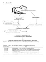
FIGURE 2.23 Inboard MOTOR, vertical direction.
Piotrowski / Shaft Alignment Handbook, Third Edition DK4322_C002 Final Proof page 60 6.10.2006 5:21pm
60 Shaft Alignment Handbook, Third Edition
Test run #2
M2W
Test run #3
M21W
Test run #4
M36W
Test run #5
M65H
Test run #6
M55L
Test run #7
M6W
1ϫ 2ϫ 3ϫ 4ϫ 5ϫ 6ϫ 7ϫ 8ϫ 9ϫ
.01
.02
Inches per second
Frequency (orders of running speed)
.01
.02
Inches per second
Frequency (orders of running speed)
.01
.02
.01
.02
Inches per second
Frequency (orders of running speed)
Inches per second
Frequency (orders of running speed)
.01
.02
Inches per second
Frequency (orders of running speed)
Frequency (orders of running speed)
10ϫ 11ϫ 12ϫ
1ϫ 2ϫ 3ϫ 4ϫ 5ϫ 6ϫ 7ϫ 8ϫ 9ϫ 10ϫ 11ϫ 12ϫ
1ϫ 2ϫ 3ϫ 4ϫ 5ϫ 6ϫ 7ϫ 8ϫ 9ϫ 10ϫ 11ϫ 12ϫ
1ϫ 2ϫ 3ϫ 4ϫ 5ϫ 6ϫ 7ϫ 8ϫ 9ϫ 10ϫ 11ϫ 12ϫ
1ϫ 2ϫ 3ϫ 4ϫ 5ϫ 6ϫ 7ϫ 8ϫ 9ϫ 10ϫ 11ϫ 12
ϫ
1ϫ 2ϫ 3ϫ 4ϫ 5ϫ 6ϫ 7ϫ 8ϫ 9ϫ 10ϫ 11ϫ 12ϫ
.01
.02
Inches per second
FIGURE 2.24 Inboard MOTOR, axial direction.
Piotrowski / Shaft Alignment Handbook, Third Edition DK4322_C002 Final Proof page 61 6.10.2006 5:21pm
Detecting Misalignment on Rotating Machinery 61
maximum amount of rotational force occurs when the grid is in the tilted position where
bending occurs across the thickness of the grid member.
.
The seven times running speed peak that occurred in the horizontal direction on the
inboard motor bearing during the M55L run and the five times running speed peak that
occurred in the axial direction on the pump are, as yet, not completely understood as to
the source of the forcing mechanism involved. The higher multiples appear to be caused
by overloading the antifriction bearings.
Test run #2
M2W
Test run #4
M36W
Test run #5
M65H
Test run #6
M55L
Test run #7
M6W
1ϫ 2ϫ 3ϫ 4ϫ 5ϫ 6ϫ 7ϫ 8ϫ 9ϫ
.01
.02
Inches per second
Frequency (orders of running speed)
.01
.02
Inches per second
Frequency (orders of running speed)
.01
.02
Inches per second
Frequency (orders of running speed)
.01
.02
Inches per second
Frequency (orders of running speed)
Frequency (orders of running speed)
10ϫ 11ϫ 12ϫ
1ϫ 2ϫ 3ϫ 4ϫ 5ϫ 6ϫ 7ϫ 8ϫ 9ϫ 10ϫ 11ϫ 12ϫ
1ϫ 2ϫ 3ϫ 4ϫ 5ϫ 6ϫ 7ϫ 8ϫ 9ϫ 10ϫ 11ϫ 12ϫ
1ϫ 2ϫ 3ϫ 4ϫ 5ϫ 6ϫ 7ϫ 8ϫ 9ϫ 10ϫ 11ϫ 12ϫ
1ϫ 2ϫ 3ϫ 4ϫ 5ϫ 6ϫ 7ϫ 8ϫ 9ϫ 10ϫ 11ϫ 12
ϫ
.01
.02
Inches per second
FIGURE 2.25 Inboard PUMP, horizontal direction.
Piotrowski / Shaft Alignment Handbook, Third Edition DK4322_C002 Final Proof page 62 6.10.2006 5:21pm
62 Shaft Alignment Handbook, Third Edition
2.2.8 BEFORE AND AFTER VIBRATION RESULTS FOUND ON A MISALIGNED
MOTOR AND PUMP
This case history shows actual alignment and vibration data from a drive system that had
been operating under a misalignment condition. Vibration information was collected before
shutdown and realignment, the unit was then aligned properly, started back up, and vibration
Test run #2
M2W
Test run #4
M36W
Test run #5
M65H
Test run #6
M55L
Test run #7
M6W
1ϫ 2ϫ 3ϫ 4ϫ 5ϫ 6ϫ 7ϫ 8ϫ 9ϫ
.01
.02
Inches per second
Frequency (orders of running speed)
10ϫ 11ϫ 12ϫ
1ϫ 2ϫ 3ϫ 4ϫ 5ϫ 6ϫ 7ϫ 8ϫ 9ϫ 10ϫ 11ϫ 12ϫ
1ϫ 2ϫ 3ϫ 4ϫ 5ϫ 6ϫ 7ϫ 8ϫ 9ϫ 10ϫ 11ϫ 12ϫ
1ϫ 2ϫ 3ϫ 4ϫ 5ϫ 6ϫ 7ϫ 8ϫ 9ϫ 10ϫ 11ϫ 12ϫ
1ϫ 2ϫ 3ϫ 4ϫ 5ϫ 6ϫ 7ϫ 8ϫ 9ϫ 10ϫ 11ϫ 12
ϫ
.01
.02
Inches per second
Frequency (orders of running speed)
.01
.02
Inches per second
Frequency (orders of running speed)
.01
.02
Inches per second
Frequency (orders of running speed)
Frequency (orders of running speed)
.01
.02
Inches per second
FIGURE 2.26 Inboard PUMP, vertical direction.
Piotrowski / Shaft Alignment Handbook, Third Edition DK4322_C002 Final Proof page 63 6.10.2006 5:21pm
Detecting Misalignment on Rotating Machinery 63
Test run #2
M2W
Test run #3
M21W
Test run #4
M36W
Test run #5
M65H
Test run #6
M55L
Test run #7
M6W
1ϫ 2ϫ 3ϫ 4ϫ 5ϫ 6ϫ 7ϫ 8ϫ 9ϫ 10ϫ 11ϫ 12ϫ
1ϫ 2ϫ 3ϫ 4ϫ 5ϫ 6ϫ 7ϫ 8ϫ 9ϫ 10ϫ 11ϫ 12ϫ
1ϫ 2ϫ 3ϫ 4ϫ 5ϫ 6ϫ 7ϫ 8ϫ 9ϫ 10ϫ 11ϫ 12ϫ
1ϫ 2ϫ 3ϫ 4ϫ 5ϫ 6ϫ 7ϫ 8ϫ 9ϫ 10ϫ 11ϫ 12ϫ
1ϫ 2ϫ 3
ϫ 4ϫ 5ϫ 6ϫ 7ϫ 8ϫ 9ϫ 10ϫ 11ϫ 12ϫ
1ϫ 2ϫ 3ϫ 4ϫ 5ϫ 6ϫ 7ϫ 8ϫ 9ϫ 10ϫ 11ϫ 12ϫ
.01
.02
Inches per second
Frequency (orders of running speed)
.01
.02
Inches per second
Frequency (orders of running speed)
.01
Inches per second
Frequency (orders of running speed)
Inches per second
Frequency (orders of running speed)
.01
.02
.01
.02
.02
Inches per second
Frequency (orders of running speed)
.01
.02
Inches per second
Frequency (orders of running speed)
FIGURE 2.27 Inboard PUMP, axial direction.
Piotrowski / Shaft Alignment Handbook, Third Edition DK4322_C002 Final Proof page 64 6.10.2006 5:21pm
64 Shaft Alignment Handbook, Third Edition
data taken again. Figure 2.30 shows the as-found and final alignment-data. Figure 2.31 shows
the before and after radial vibration spectral data on the motor. Figure 2.32 shows the before
and after radial vibration spectral data on the pump. Figure 2.33 shows the before and
after axial vibration spectral data on both the motor and the pump. Notice that the radial
and axial vibrations on the motor increased and the vibration on the pump decreased after the
misalignment was corrected.
Test run #2
M2W
Test run #4
M36W
Test run #5
M65H
Test run #6
M55L
Test run #7
M6W
1ϫ 2ϫ 3ϫ 4ϫ 5ϫ 6ϫ 7ϫ 8ϫ 9ϫ 10ϫ 11ϫ 12ϫ
1ϫ 2ϫ 3ϫ 4ϫ 5ϫ 6ϫ 7ϫ 8ϫ 9ϫ 10ϫ 11ϫ 12ϫ
1ϫ 2ϫ 3ϫ 4ϫ 5ϫ 6ϫ 7ϫ 8ϫ 9ϫ 10ϫ 11ϫ 12ϫ
1ϫ 2ϫ 3ϫ 4ϫ 5ϫ 6ϫ 7ϫ 8ϫ 9ϫ 10ϫ 11ϫ 12ϫ
1ϫ 2ϫ 3ϫ 4ϫ 5ϫ 6ϫ 7ϫ 8ϫ 9ϫ 10ϫ 11ϫ 12ϫ
.01
.02
Inches per second
Frequency (orders of running speed)
.01
.02
Inches per second
Frequency (orders of running speed)
.01
.02
Inches per second
Frequency (orders of running speed)
.01
.02
Inches per second
Frequency (orders of running speed)
.01
.02
Inches per second
Frequency (orders of running speed)
FIGURE 2.28 Outboard PUMP, horizontal direction.
Piotrowski / Shaft Alignment Handbook, Third Edition DK4322_C002 Final Proof page 65 6.10.2006 5:21pm
Detecting Misalignment on Rotating Machinery 65
2.2.9 WHY VIBRATION LEVELS OFTEN DECREASE WITH INCREASING MISALIGNMENT
As illustrated in Figure 2.2, rotating machinery shafts are exposed to two types of forces.
Static forces that act in one direction and dynamic forces that change their direction. Static
forces are also called preloads. Preloads on shafts and bearings are caused from many of the
following sources:
Test run #2
M2W
Test run #4
M36W
Test run #5
M65H
Test run #6
M55L
Test run #7
M6W
1ϫ 2ϫ 3ϫ 4ϫ 5ϫ 6ϫ 7ϫ 8ϫ 9ϫ 10ϫ 11ϫ 12ϫ
1ϫ 2ϫ 3ϫ 4ϫ 5ϫ 6ϫ 7ϫ 8ϫ 9ϫ 10ϫ 11ϫ 12ϫ
1ϫ 2ϫ 3ϫ 4ϫ 5ϫ 6ϫ 7ϫ 8ϫ 9ϫ 10ϫ 11ϫ 12ϫ
1ϫ 2ϫ 3ϫ 4ϫ 5ϫ 6ϫ 7ϫ 8ϫ 9ϫ 10ϫ 11ϫ 12ϫ
1ϫ 2ϫ 3
ϫ 4ϫ 5ϫ 6ϫ 7ϫ 8ϫ 9ϫ 10ϫ 11ϫ 12ϫ
.01
.02
Inches per second
Frequency (orders of running speed)
.01
.02
Inches per second
Frequency (orders of running speed)
.01
.02
Inches per second
Frequency (orders of running speed)
.01
.02
Inches per second
Frequency (orders of running speed)
.01
.02
Inches per second
Frequency (orders of running speed)
FIGURE 2.29 Outboard PUMP, vertical direction.
Piotrowski / Shaft Alignment Handbook, Third Edition DK4322_C002 Final Proof page 66 6.10.2006 5:21pm
66 Shaft Alignment Handbook, Third Edition
Drive train dimensions
Deionized water distribution pump 2
Alignment summary
Motor
10 6.5 5 7 7.5
in.in.in.in.in.
As found
Reverse indicator readings
Pump to motor
Motor to pump
0
T
T
S
S
B
B
N
N
T
s
B
0
2
0
N
T
s
B
N
3
29 24
−65
Motor
20 mils
1 in
Motor
10 mils
Motor
Pump
Pump
Top view
Motor
Pump
north
Shim changes at foundation boltsShim changes at foundation bolts
Motor
Motor
Move outboard foot
45 mils
down
Pump
1
in
Side view
Pump Pump
−4
−2
−1
3
0
Pump to motor Motor to pump
53
0
−68
Reverse indicator readings
Final
Pump
up
Side view
up
Top view
north
20 1 inmils
10
1in
mils
Lateral (sideways) changes at foundation bolts
Lateral (sideways) changes at foundation bolts
Motor Motor
Move outboard foot
22 mils
north
Move outboard foot
144 mils
north
Move outboard foot
78 mils
north
Move outboard foot
11 mils
north
Alignment tolerance guidelinesAlignment tolerance guidelines
Misalignment is the deviation of relative
shaft position from a colinear axis of
rotation, measures at the points of
power transmissin when equipment is
running at normal operating conditions.
Misalignment is the deviation of relative
shaft position from a colinear axis of
rotation, measures at the points of
power transmissin when equipment is
running at normal operating conditions.
2.0
.063
.056
.050
.044
.038
.031
.025
.019
Angle ( in degrees)
Angle ( in degrees)
.013
.006
.063
.056
.050
.044
.038
.031
.025
.019
.013
.006
1.8
1.6
1.4
1.2
1.0
0.8
0.6
0.4
Maximum devation at either point of
power transmission (mils/in.)
Maximum devation at either point of
power transmission (mils/in.)
0.2
2.0
1.8
1.6
1.4
1.2
1.0
0.8
0.6
0.4
0.2
246 810
Speed (rpm ϫ 1000)
The maximum alignment devation is .7 mils/in.
at the motor in the lateral direction
The maximum alignment devation is .7 mils/in.
at the motor in the lateral direction
20 30
Pump Pump
Move inboard foor
37 mils
down
Move inboard foor
5 mils
up
Move inboard foor
2 mils
up
Unacceptable
Acceptable
Acceptable
Unacceptable
Excellent
Excellent
246810
Speed (rpm ϫ 1000)
20
FIGURE 2.30 As-found and final alignment data on motor and pump.
Piotrowski / Shaft Alignment Handbook, Third Edition DK4322_C002 Final Proof page 67 6.10.2006 5:21pm
Detecting Misalignment on Rotating Machinery 67
0
0.5
0.4
0.3
0.2
0.1
0
0.5
0.4
0.3
0.2
0.1
0
0 6000 12000 18000 24000 30000
0
0
0.1
0.2
0.3
0.4
0.5
DIDstrb P2-MIV Motor Inboard Vertical
DIDstrb P2-MIH Motor Inboard Vertical DIDstrb P2-MIH Motor Inboard Vertical
DIDstrb P2-MIV Motor Inboard Vertical
6000 12000 18000 24000 30000
0 6000 12000 18000 24000 30000
0 6000 12000
Frequency in cpm
Frequency in cpm
Frequency in cpm Frequency in cpm
Frequency in cpm
Frequency in cpm
18000 24000 30000
0
0.1
0.2
Peak velocity in./s
0.3
0.4
0.5
DIDstrb P2-MOH Motor Outboard Horizontal
Before alignment After alignment
DIDstrb P2-MOH Motor Outboard Horizontal
0
0.1
0.2
0.3
0.4
0.5
0
0 6000 12000 18000 24000 30000
0.1
0.2
0.3
0.4
0.5
0
0.1
0.2
0.3
0.4
0.5
0
0 6000 30000240001800012000
0.1
0.2
0.3
0.4
0.5
3556.
3555.
6000
DIDstrb P2-MOV Motor Outboard Vertical DIDstrb P2-MOV Motor Outboard Vertical
12000
Frequency in cpm
18000 24000 30000 0 6000 12000
Frequency in cpm
18000 24000 30000
FIGURE 2.31 Before and after radial vibration data on motor.
Piotrowski / Shaft Alignment Handbook, Third Edition DK4322_C002 Final Proof page 68 6.10.2006 5:21pm
68 Shaft Alignment Handbook, Third Edition
Before alignment
After alignment
Deionized water distribution pump 2 ¥ pump vibration data
0.5
DIDstrb P2-PIH Pump Inboard Horizontal
DIDstrb P2-PIV Pump Inboard Vertical
DIDstrb P2-POH Pump Outboard Horizontal
DIDstrb P2-POV Pump Outboard Vertical
DIDstrb P2-POV Pump Outboard Vertical
DIDstrb P2-POH Pump Outboard Horizontal
DIDstrb P2-PIH Pump Inboard Horizontal
DIDstrb P2-PIH Pump Inboard Vertical
0.4
0.3
0.2
Peak velocity in in/s
0.1
0
0.5
0.4
0.3
0.2
0.1
0
0
6000
12000 18000
24000
300000 6000 12000 18000 24000 30000
0.5
0.4
0.3
0.2
0.1
0
0
6000
12000 18000
Frequency in cpm
Frequency in cpm
Frequency in cpm
Fre
q
uenc
y
in c
p
m
Frequency in cpm
Frequency in cpm
Frequency in cpm
Frequency in cpm
24000
30000
0.5
0.4
0.3
0.2
0.1
0
0.5
0.4
0.3
0.2
0.1
0
0
6000
12000 18000
24000
30000
0.5
0.4
0.3
0.2
0.1
0
0 6000 12000 18000 24000 30000
0.5
0.4
0.3
0.2
0.1
0
0 6000 12000 18000 24000 30000
0
6000
12000 18000
24000
30000
0.5
0.4
0.3
0.2
0.1
0
0
6000
12000 18000
24000
30000
FIGURE 2.32 Before and after radial vibration data on pump.
Piotrowski / Shaft Alignment Handbook, Third Edition DK4322_C002 Final Proof page 69 6.10.2006 5:21pm
Detecting Misalignment on Rotating Machinery 69
.
Gravitational force
.
V-belt or chain tension
.
Shaft misalignment
.
Some types of hydraulic or aerodynamic loads
Dynamic loads on shafts and bearings are caused by some of the following sources (not a
complete list by any means):
.
Out of balance condition (i.e., the center of mass is not coincident with the centerline of
rotation)
.
Eccentric rotor components or bent shafts (another form of unbalance)
.
Damaged antifriction bearings
.
Intermittent, period rubs
.
Gear tooth contact
.
Pump or compressor impeller blades passing by a stationary object
.
Electromagnetic forces
Simply stated, vibration is motion. Vibratory motion in machinery is caused by forces
that change their direction. For example, a rotor that is out of balance and is not
0.5
0.4
0.3
0.2
0.1
0
0 6000 12000 18000 2000 3000
Peak velocity in in/s
DIDstrb P2-MIA Motor Inboard Axial
Frequency in cpm
Before alignment
After alignment
DIDstrb P2-MIA Motor Inboard Axial
0.5
0.4
0.3
0.2
0.1
0
0 6000 12000 18000 2000 3000
Frequency in cpm
DIDstrb P2-POA Pump Outboard Axial DIDstrb P2-POA Pump Outboard Axial
0.5
0.4
0.3
0.2
0.1
0
0.5
0.4
0.3
0.2
0.1
0
0 6000 12000 18000 2000 3000 0 6000 12000 18000 2000 3000
Frequency in cpm Frequency in cpm
3556.
7191.
FIGURE 2.33 Before and after axial vibration data on motor and pump.
Piotrowski / Shaft Alignment Handbook, Third Edition DK4322_C002 Final Proof page 70 6.10.2006 5:21pm
70 Shaft Alignment Handbook, Third Edition
rotating, does not vibrate. As soon as the imbalanced rotor begins to spin, it also begins
to vibrate. This occurs because the ‘‘heavy spot’’ is changing its position, causing the
(centrifugal) force to change its direction. The rotor=bearing=support system, being
elastic, consequentially begins to flex or move as these alternating forces begin to act
on the machine.
Another detectable vibration pattern exists in gears and is commonly referred to as
gear mesh. Gear mesh can be detected as forces increase or subside as each tooth comes in
contact with another. Other types of mechanical or electrical problems that can be detected
through vibration analysis can be traced back to the fact that forces are somehow changing
their direction.
On the other hand, when two or more shafts are connected together by some flexible or
rigid element where the centerlines of each machine are not collinear, the forces transferred
from shaft to shaft are acting in one direction only. These forces do not change their
direction, as an imbalance condition does. If a motor shaft is higher than a pump shaft
by 50 mils, the motor shaft is trying to pull the pump shaft upward to come in line with the
motor shaft position. Conversely, the pump shaft is trying to pull the motor shaft downward
to come in line with the pump shaft position. The misalignment forces will begin to bend the
shafts, not flutter them around like the tail of a fish.
Static forces caused by misalignment act in one direction only, which is quite different than
the dynamic forces that generate vibration. Under this pretense, how could misalignment ever
cause vibration to occur? If anything, misalignment should diminish the capacity for motion
to occur in a rotor=bearing=support system.
2.2.10 KNOWN VIBRATION SPECTRAL SIGNATURES OF MISALIGNED FLEXIBLE COUPLINGS
Despite the fact that shaft misalignment may decrease the amount of vibration in rotating
machinery, vibration can and does occur due to this condition. As previously mentioned, it
has been observed that the vibration spectral pattern of misaligned rotating machinery
will frequently be different depending on the type of flexible coupling connecting the two
shaft together.
Figure 2.34 through Figure 2.39 show vibration patterns that have been observed on
misaligned rotating machinery with different types of flexible couplings. Notice that the
vibration peaks are occurring at running speed (1X) or multiples of running speed (2X, 3X,
4X, etc.).
2.2.11 VIBRATION CHARACTERISTICS OF MISALIGNED MACHINERY SUPPORTED IN SLIDING
TYPE BEARINGS
The vibration spectral patterns in Figure 2.34 through Figure 2.39 were seen on rotating
machinery supported in rolling element type bearings. Frequently a different pattern emerges
on machinery supported in sliding type bearings as shown in Figure 2.40.
2.2.12 USING INFRARED THERMOGRAPHY TO DETECT MISALIGNMENT
A very interesting study was performed by two maintenance technicians from a bottling
company in 1991. The test was conducted by coupling a 10 hp motor to a 7200 W electric
generator. A specific flexible coupling was installed between the motor and the generator; the
unit was then accurately aligned and then started up. Vibration, ultrasound, and thermal
Piotrowski / Shaft Alignment Handbook, Third Edition DK4322_C002 Final Proof page 71 6.10.2006 5:21pm
Detecting Misalignment on Rotating Machinery 71
imaging data was then collected after 10 min run time. The unit was then shutdown, 10 mils of
shims were placed under all 4 ft of the motor, the drive system started back up and the data
was collected again. This was repeated several times with an additional 10 mils of shims
installed under the motor feet each time. After the motor and generator drive was misaligned
1ϫ 2ϫ 3ϫ 4ϫ 5ϫ 6ϫ 7ϫ 8ϫ 9ϫ 10ϫ
1ϫ 2ϫ 3ϫ 4ϫ 5ϫ 6ϫ 7ϫ 8ϫ 9ϫ 10ϫ
Motor driven ANSI pump
J. Lorenc horizontal misalignment at 90 mils IB & OB
Jaw coupling
Various vibration responses to misalignment
Motor driven generator test
D. Nower horizontal and angular misalignment at 15 mils/in.
FIGURE 2.34 Observed vibration patterns on misaligned jaw-type couplings. (Courtesy of Lovejoy,
Downers Grove, IL. With permission.)
Piotrowski / Shaft Alignment Handbook, Third Edition DK4322_C002 Final Proof page 72 6.10.2006 5:21pm
72 Shaft Alignment Handbook, Third Edition
Motor driven ANSI pump
J. Lorenc horizontal misalignment at 30 mils IB & OB
Gear coupling
Various vibration responses to misalignment
Gas/power turbine driven compressor
J. Piotrowski horizontal misali
g
nment at 65 mils IB & OB
1ϫ 2ϫ 3ϫ 4ϫ 5ϫ 6ϫ 7ϫ 8ϫ 9ϫ 10ϫ
1ϫ 2ϫ 3ϫ 4ϫ 5ϫ 6ϫ 7ϫ 8ϫ 9ϫ 10ϫ
FIGURE 2.35 Observed vibration patterns on misaligned gear type couplings. (Courtesy of Rexmord
Coupling Group, Milwaukee, WI. With permission.)
Piotrowski / Shaft Alignment Handbook, Third Edition DK4322_C002 Final Proof page 73 6.10.2006 5:21pm
Detecting Misalignment on Rotating Machinery 73
Motor driven ANSI pump
S. Chancey vertical misalignment 50 mils at IB & 75 mils at OB
J. Lorenc horizontal misalignment at 90 mils IB & OB
Metal ribbon coupling
Various vibration responses to misalignment
Motor driven generator test
D. Nower horizontal misalignment at 50 mils IB & OB
Motor driven centrifugal pump
J. Piotrowski horizontal misalignment at 36 mils IB & OB
1ϫ 2ϫ 3ϫ 4ϫ 5ϫ 6ϫ 7ϫ 8ϫ 9ϫ 10ϫ
1ϫ 2ϫ 3ϫ 4ϫ 5ϫ 6ϫ 7ϫ 8ϫ 9ϫ 10ϫ
1ϫ 2ϫ 3ϫ 4ϫ 5ϫ 6ϫ 7ϫ 8ϫ 9ϫ 10ϫ
FIGURE 2.36 Observed vibration patterns on misaligned metal ribbon-type couplings. (Courtesy of
Rexmord Coupling Group, Milwaukee, IL. With permission.)
Piotrowski / Shaft Alignment Handbook, Third Edition DK4322_C002 Final Proof page 74 6.10.2006 5:21pm
74 Shaft Alignment Handbook, Third Edition
30–40 mils, the flexible coupling being tested was removed, a different flexible coupling design
was then installed, the shims were removed from the motor to get back to near perfect
alignment, and the process was repeated.
Figure 2.41 through Figure 2.46 show the results of the six different flexible couplings
that were tested. Notice that as the misalignment increased, so too did the temperature
of the coupling or of the flexing element. The increase in temperature is somewhat
linear as illustrated in the temperature graphs with each coupling tested. Disappoint-
ingly, however, the vibration and ultrasound data was never published with the
infrared data.
In addition, there must be a word of caution here because it is very tempting to
make generalizations from this data. Not every flexible or rigid coupling will increase
in temperature when subjected to misalignment conditions. The flexible couplings used in
this test were mechanically flexible couplings (the chain and metal ribbon types) or elasto-
meric types.
In mechanically flexible couplings the heat is generated as the metal grid slides back and
forth across the tooth slots in the coupling hubs or as the chain rollers slide across the
sprocket teeth as the coupling elements attempt to accept the misalignment condition. In
the elastomeric couplings, the elastomer is heated through some sliding friction but pri-
marily by shear and compression forces as these coupling elements attempt to accept their
misalignment conditions.
What would have happened if a flexible disk or diaphragm type coupling was also
tested? Flexible disk or diaphragm couplings accept misalignment conditions by elastically
bending the two disk packs or diaphragms and virtually no heat will be generated by
the flexure of metal disks as these types of couplings attempt to accommodate any
misalignment conditions.
2.2.13 POWER LOSS DUE TO SHAFT MISALIGNMENT
It has been widely publicized that shaft misalignment will cause the driver to work harder and
therefore take more energy or power to run the drive system. However, a study conducted by
the University of Tennessee in 1997 where both 50 and 60 hp motors were purposely misaligned
to dynamometers using four different types of couplings and subjecting each coupling to 15
misalignment conditions came to the following conclusions: ‘‘The results of these tests show
no significant correlation between misalignment and changes in efficiency when the tested
couplings were operated within the manufacturer’s recommended range. Power consumption
and power output remained constant regardless of the alignment condition.’’
2.2.14 THE MOST EFFECTIVE WAY TO DETERMINE IF MISALIGNMENT EXISTS
After years of study, one invariable conclusion can be made. Misalignment disguises itself
very well on the operating rotating machinery. There are no easy or inexpensive ways
to determine if rotating machinery is misaligned while it is running. The most effective way
to determine if a misalignment condition exists is to shut the drive system down, safety tag
and lock out the machinery, remove the coupling guard, and employ one of the alignment
measurement methods described in Chapter 7 to see if a misalignment condition is present.
Even if the alignment looks good when you do an off-line check, running misalignment may
occur. So it is suggested that you also review Chapter 9, which discusses off-line to running
machinery movement.
Piotrowski / Shaft Alignment Handbook, Third Edition DK4322_C002 Final Proof page 75 6.10.2006 5:21pm
Detecting Misalignment on Rotating Machinery 75
Motor driven BFW pump
Motor driven demonstrator
J. Piotrowski horizontal misalignment at 80 mils IB & OB
Flexible disk-type coupling
Various vibration responses to misalignment
Motor driven motor experimental test
D. Dewell parallel at 96 mils
Motor driven generator test
D. Nower horizontal and angular misalignment at 75 mils high
1ϫ 2ϫ 3ϫ 4ϫ 5ϫ 6ϫ 7ϫ 8ϫ 9ϫ 10ϫ
1ϫ 2ϫ 3ϫ 4ϫ 5ϫ 6ϫ 7ϫ 8ϫ 9ϫ 10ϫ
1ϫ 2ϫ 3ϫ 4ϫ 5ϫ 6ϫ 7ϫ 8ϫ 9ϫ 10ϫ
FIGURE 2.37 Observed vibration patterns on misaligned flexible disk-type couplings. (Courtesy of
Thomas Rexnord, Warren, PA. With permission.)
Piotrowski / Shaft Alignment Handbook, Third Edition DK4322_C002 Final Proof page 76 6.10.2006 5:21pm
76 Shaft Alignment Handbook, Third Edition
Motor driven ANSI pump
J. Lorenc horizontal misalignment at 90 mils IB & OB
J. Piotrowski horizontal misalignment at 80 mils IB & OB
Rubber tire-type coupling
Various vibration responses to misalignment
Motor driven generator test
D. Nower horizontal and angular misalignment at 75 mils high
1ϫ 2ϫ 3ϫ 4ϫ 5ϫ 6ϫ 7ϫ 8ϫ 9ϫ 10ϫ
1ϫ 2ϫ 3ϫ 4ϫ 5ϫ 6ϫ 7ϫ 8ϫ 9ϫ 10ϫ
FIGURE 2.38 Observed vibration patterns on misaligned flexible disk-type couplings. (Courtesy of
Dodge-Reliance Electric, Cleveland, OH. With permission.)
Piotrowski / Shaft Alignment Handbook, Third Edition DK4322_C002 Final Proof page 77 6.10.2006 5:21pm
Detecting Misalignment on Rotating Machinery 77
Motor driven pump—Motor IB Hrz
vertical misalignment
Motor was 100 mils high at OB, 46 mils high at IB
Motor driven pump—Pump IB Hrz
vertical misalignment
Motor was 100 mils high at OB, 46 mils high at IB
Motor driven pump—Motor OB Hrz
vertical misalignment
Motor was 100 mils high at OB, 46 mils high at IB
TB Woods-type coupling
various vibration responses to misalignment
1ϫ 2ϫ 3ϫ 4ϫ 5ϫ 6ϫ 7ϫ 8ϫ 9ϫ 10ϫ
1ϫ 2ϫ 3ϫ 4ϫ 5ϫ 6ϫ 7ϫ 8ϫ 9ϫ 10ϫ
1ϫ 2ϫ 3ϫ 4ϫ 5ϫ 6ϫ 7ϫ 8ϫ 9ϫ 10ϫ
FIGURE 2.39 Observed vibration patterns on misaligned flexible disk-type couplings. (Courtesy of T. B.
Woods and Sons, Chambersburg, PA. With permission.)
(continued )
Piotrowski / Shaft Alignment Handbook, Third Edition DK4322_C002 Final Proof page 78 6.10.2006 5:21pm
78 Shaft Alignment Handbook, Third Edition
Sliding type
bearing
Force
Proximity
probes
Shaft
When the signals from two proximity probes
are combined together in a two channel
oscilloscope or vibration analyzer, the orbital
motion of the shaft can be observed (called
a Lissajous pattern).
A typical shaft orbit in a sliding type bearing
with no external forces applied to the shaft
is shown to the right. Even if a pure imbalance
condition existed causing an even radial force,
the orbital pattern would be elliptical due to
the different horizontal and vertical stiffnesses
of the machine case.
If a downward force from shaft misalignment
is now applied to the rotor/bearing system,
the elliptical orbit begins to “flatten out”. The
static misalignment force is limiting the
amount of shaft movement in the vertical
direction.
If the force from misalignment increase the
orbit continues to flatten and distort.
As the force begins to steadily increase, the
orbit begins to take a pickle shape.
When the force is great enough, the orbit
changes shape to a figure “8”, hence a 2ϫ
running speed vibration component appears.
FIGURE 2.40 Observed vibration orbital patterns on rotors supported in sliding type bearings.
Piotrowski / Shaft Alignment Handbook, Third Edition DK4322_C002 Final Proof page 79 6.10.2006 5:21pm
Detecting Misalignment on Rotating Machinery 79
(a) (b)
(c)
Temperature (ЊF)
Misalignment(d)
0
50
100
150
0 mils
10 mils
20 mils
30 mils
40 mils
FIGURE 2.41 Observed temperature patterns on misaligned jaw-type coupling. (a) A photograph of
the coupling, (b) an infrared image of the coupling running under good alignment conditions, (c) an
infrared image of the coupling running with the worst misalignment condition (d) temperature of
coupling at each 10 mil misalignment condition. (Photos and data courtesy of Infraspection Institute,
Shelburne, VT.)
Piotrowski / Shaft Alignment Handbook, Third Edition DK4322_C002 Final Proof page 80 6.10.2006 5:21pm
80 Shaft Alignment Handbook, Third Edition
(a)
(c)
(d)
(b)
Temperature (8F)
Misalignment
0
50
100
150
0 mils
10 mils
20 mils
30 mils
40 mils
FIGURE 2.42 Observed temperature patterns on misaligned rubber tire-type coupling. Upper right
photo shows infrared image of coupling running under good alignment conditions. Lower right photo
shows coupling running under ‘‘worst case’’ misalignment condition indicated by rightmost bar on
temperature graph. (Photos and data courtesy of Infraspection Institute, Shelburne, VT.)
Piotrowski / Shaft Alignment Handbook, Third Edition DK4322_C002 Final Proof page 81 6.10.2006 5:21pm
Detecting Misalignment on Rotating Machinery 81
(a)
(c)
(d)
(b)
Temperature (8F)
Misalignment
0
100
200
0 mils
10 mils
20 mils
30 mils
40 mils
FIGURE 2.43 Observed temperature patterns on misaligned rubber insert type coupling. (a) A photo-
graph of the coupling, (b) an infrared image of the coupling running under good alignment conditions,
(c) an infrared image of the coupling running with the worst misalignment condition (d) temperature of
coupling at each 10 mil misalignment condition. (Photos and data courtesy of Infraspection Institute,
Shelburne, VT.)
Piotrowski / Shaft Alignment Handbook, Third Edition DK4322_C002 Final Proof page 82 6.10.2006 5:21pm
82 Shaft Alignment Handbook, Third Edition
(a)
(c)
(b)
(d)
Temperature (8F)
Misalignment
0
50
100
150
0 mils
10 mils
20 mils
30 mils
40 mils
FIGURE 2.44 Observed temperature patterns on misaligned rubber ‘‘gear’’ type coupling. (a) A photo-
graph of the coupling, (b) an infrared image of the coupling running under good alignment conditions,
(c) an infrared image of the coupling running with the worst misalignment condition (d) temperature of
coupling at each 10 mil misalignment condition. (Photos and data courtesy of Infraspection Institute,
Shelburne, VT.)
Piotrowski / Shaft Alignment Handbook, Third Edition DK4322_C002 Final Proof page 83 6.10.2006 5:21pm
Detecting Misalignment on Rotating Machinery 83
(a)
(c)
(d)
(b)
0
50
100
150
Temperature (8F)
Misalignment
0 mils
10 mils
20 mils
30 mils
40 mils
FIGURE 2.45 Observed temperature patterns on misaligned metal ribbon-type coupling. (a) A photo-
graph of the coupling, (b) an infrared image of the coupling running under good alignment conditions,
(c) an infrared image of the coupling running with the worst misalignment condition (d) temperature of
coupling at each 10 mil misalignment condition. (Photos and data courtesy of Infraspection Institute,
Shelburne, VT.)
Piotrowski / Shaft Alignment Handbook, Third Edition DK4322_C002 Final Proof page 84 6.10.2006 5:21pm
84 Shaft Alignment Handbook, Third Edition