Handbook Of Shaft Alignment Episode 1 Part 9 potx
Bạn đang xem bản rút gọn của tài liệu. Xem và tải ngay bản đầy đủ của tài liệu tại đây (1.15 MB, 30 trang )
FIGURE 5.46 Cleaning the pump feet using 180 grit emery cloth wrapped around a 1=8 in. thick steel
bar and ‘‘sawing’’ back and forth to clean the underside of the machine foot and the base plate at the
same time.
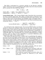
FIGURE 5.47 The underside of this motor foot is ‘‘hollow.’’ Make sure for using the right size shims to
get as much contact as possible here.
Piotrowski / Shaft Alignment Handbook, Third Edition DK4322_C005 Final Proof page 210 26.9.2006 8:36pm
210 Shaft Alignment Handbook, Third Edition
6. Once all of the bolts have been loosened, review what you observed when each bolt was
loosened. If more than 2–3 mils of movement occurred when just one of the bolts
was loosened, then there is probably a soft foot condition at that foot only. Remove
any soft foot shims under that foot and remeasure four points around that bolt-hole
FIGURE 5.48 Soft foot correction shim stack.
FIGURE 5.49 Soft foot correction shims for a motor.
FIGURE 5.50 Soft foot correction shims stack.
Piotrowski / Shaft Alignment Handbook, Third Edition DK4322_C005 Final Proof page 211 26.9.2006 8:36pm
Preliminary Alignment Checks 211
with feeler gauges and install a flat shim or shim wedge to correct the observed
condition. If more than 2–3 mils of movement were noticed when several of the bolts
were loosened, then there is probably a soft foot condition at each one of those feet.
Remove any soft foot shims under those feet and remeasure four points around those
bolt-holes with feeler gauges and install flat shims or shim wedges to correct the
observed condition.
7. Repeat the procedure if additional corrections are required.
5.6.3 SHAFT MOVEMENT METHOD (THIRD CHOICE)
1. Tighten all of the foot bolts holding the machine in place.
2. Attach a bracket to one shaft, place a dial indicator on the topside of the other shaft,
and zero the indicator at mid-range.
3. Sequentially loosen one-foot bolt at a time observing for any movement at the indicator
when each bolt is loosened.
4. If there were more than 2–3 mils of movement when only one of the bolts were loosened,
then there is probably a soft foot condition at that foot only. Remove any soft foot
shims under that foot and remeasure four points around that bolt-hole with feeler
gauges and install a flat shim or shim wedge to correct the observed condition. If
more than 2–3 mils of movement were noticed when several of the bolts were loosened,
then there is probably a soft foot condition at each one of those feet. Remove any soft
foot shims under those feet and remeasure four points around those bolt-holes with
feeler gauges and install flat shims or shim wedges to correct the observed condition.
5. Repeat the procedure if additional corrections are required.
5.6.4 SINGLE BOLT–SINGLE INDICATOR METHOD (LAST CHOICE)
1. Tighten all of the foot bolts holding the machine in place.
2. Place a dial indicator at one of the feet on the machine case. Anchor the dial indicator to
the frame or base and place the dial indicator stem as close as possible to the bolt-hole,
insure that the stem is touching the top of the foot, and zero the indicator at mid-range.
3. Loosen the bolt where the indicator is located, watching the indicator at that foot for
any movement. If more than 2–3 mils of movement are detected, there is probably some
soft foot still remaining at that foot. Remove any soft foot shims under that foot and
remeasure four points around that bolt-hole with feeler gauges and install a flat shim or
shim wedge to correct the observed condition. Retighten the bolt.
4. Sequentially move the indicator to each one of the feet, loosening that bolt and watching
the indicator for any movement. If more than 2–3 mils of movement are detected when
each bolt was loosened, there is probably some soft foot still remaining at that foot.
Remove any soft foot shims under that foot and remeasure four points around that bolt-
hole with feeler gauges and install a flat shim or shim wedge to correct the observed
condition. Retighten each bolt.
5. Repeat the procedure if additional corrections are required.
Once the soft foot has been corrected, the shims will stay there for the rest of the alignment
process. We may be adding more shims later on to change the height or ‘‘pitch’’ of the
machine case but the shims used to correct the soft foot condition will remain in place.
As illustrated in Figure 5.51 through Figure 5.53, a soft foot condition can occur on other
machinery components besides the machine case itself, in this instance, it is a pillow block
bearing and its mating pedestal. Figure 5.54 shows a turbine bearing with lateral support
Piotrowski / Shaft Alignment Handbook, Third Edition DK4322_C005 Final Proof page 212 26.9.2006 8:36pm
212 Shaft Alignment Handbook, Third Edition
FIGURE 5.51 Soft foot correction shims for a pillow block bearing on a fan.
FIGURE 5.52 Checking for lift with a magnetic base and dial indicator on a machine foot.
FIGURE 5.53 Checking for lift with a magnetic base and dial indicator on a fan frame.
Piotrowski / Shaft Alignment Handbook, Third Edition DK4322_C005 Final Proof page 213 26.9.2006 8:36pm
Preliminary Alignment Checks 213
plates that are bolted to the condenser shell. There was uneven contact between the lateral
support plates and the condenser shell flange. Soft foot shims had to be installed here to
provide sufficient contact to achieve the desired lateral stiffness.
Figure 5.55 through Figure 5.58 show another pillow block bearing that was not making
adequate contact. Figure 5.55 shows the underside of the lower pillow block casting. Notice
that it too is ‘‘hollow.’’ To determine where the lower casting was not touching the pedestal,
5-mil thick shim strip were placed on the pedestal to elevate the lower casting a known
distance. Plastigage was then placed at the areas of contact, the bearing set down and the bolts
tightened slightly. After loosening the bolts and removing the lower pillow block casting, the
amount of crush was measured using the guide on the Plastigage container sleeve as shown in
Figure 5.57. Shims were then installed where the gap was observed to be over 5 mils. Figure
5.58 shows a lift check made on the pillow block to insure the lack of contact problem was
corrected.
5.7 OTHER METHODS FOR CORRECTING SOFT FOOT PROBLEMS
For many of the readers who are reading about this problem for the first time, there is a great
tendency to disbelieve that this malady actually exists. Be forewarned, this is a time consum-
ing, frustrating process that frequently can consume more time than actually aligning the
rotating machinery itself. Despite the fact that two out of three pieces of rotating machinery
have a soft foot problem, very few solutions have been forwarded on how to correct this
problem easily.
It does seem rather silly to cut U-shaped shims into strips, L-shapes, J-shapes, or shortened
U-shapes to correct this problem but precut, U-shaped shims are commonly used in industry
to adjust the position of rotating machinery in the process of aligning equipment. But it is not
possible to correct a wedge-shaped gap condition with a flat piece of shim stock. Since many
FIGURE 5.54 Soft foot shims installed on turbine bearing lateral support plates.
Piotrowski / Shaft Alignment Handbook, Third Edition DK4322_C005 Final Proof page 214 26.9.2006 8:36pm
214 Shaft Alignment Handbook, Third Edition
FIGURE 5.55 Underside of pillow block bearing lower casting.
FIGURE 5.56 Installing shims and Plastigage for contact check.
Piotrowski / Shaft Alignment Handbook, Third Edition DK4322_C005 Final Proof page 215 26.9.2006 8:36pm
Preliminary Alignment Checks 215
people only have this precut shim stock available to them, then the only way to construct a
wedge is to ‘‘stair-step’’ pieces of shims together to construct the wedge that is needed. For
people who have a lot of time on their hands, they could actually machine a custom wedge
shape shim after they ‘‘mapped’’ out the gaps at each foot. People have actually done this.
There have been a few attempts to create a device that automatically corrects for a soft foot
condition. Proprietary plastic shims were experimented within the 1990s but they did not
seem to meet the requirements satisfactorily. They did provide some damping between the
machine and the base plate however.
Before that there were ‘‘peel away’’ shim blocks. Thin shim stock was made into a multi-
layer sandwich, where several thin shims were bonded together with a thin adhesive layer.
People would then peel away as many layers as they needed and could trim each layer to form
a wedge if desired. Since nonhardening adhesive was used, applications on machinery that ran
hot would begin to debond the layers. One always hoped the adhesive would not flow and
squeeze out since it had a thickness to it also.
FIGURE 5.57 Measuring the crushed Plastigage.
FIGURE 5.58 Checking for lift after installing the noncontact (i.e., soft foot) correction shims.
Piotrowski / Shaft Alignment Handbook, Third Edition DK4322_C005 Final Proof page 216 26.9.2006 8:36pm
216 Shaft Alignment Handbook, Third Edition
One idea from a colleague suggested that you take two 10-mil thick shims, mix up some
epoxy resin and hardener, spread the epoxy on one side of a shim, and then make a shim
‘‘sandwich,’’ install it under the foot, and then let it harden. In the event that too much epoxy
was applied, the idea suggested that you can put the shim inside a plastic bag so the excess
epoxy would flow into the bag and not adhere the machine to its base plate. Then, after the
epoxy cured, it is essential to remove the bagged shim, trim away the squeezed out epoxy,
remove the plastic bag, and reinstall the shim. I tried that one time and got yelled at for
spending too much time ‘‘goofing around’’ and not getting the alignment job done.
Another similar yet more elegant idea was developed by another colleague. These devices
were dubbed ‘‘foot plane compensators’’ and are shown in Figure 5.59 and Figure 5.60. The
underside of the foot plane compensator has channeling to allow epoxy to flow into the
cavity. An O-ring seals the perimeter to prevent the epoxy from flowing out. A special bolt
is used to attach the foot plane compensator to the underside of every foot on a machine
and then the machine is set down onto its base plate. Tubing is then placed into one of the
openings on the side of the foot plane compensator and epoxy is injected into the cavity.
Once the epoxy sets and hardens the foot plane compensator to the base plate, the special
FIGURE 5.59 Foot plane compensator. Underside view showing epoxy channels. (Courtesy of Max
Roeder Consulting, Inc., Danville, IN.)
FIGURE 5.60 Foot plane compensator. Injecting epoxy into the channels. (Courtesy of Max Roeder
Consulting, Inc., Danville, IN.)
Piotrowski / Shaft Alignment Handbook, Third Edition DK4322_C005 Final Proof page 217 26.9.2006 8:36pm
Preliminary Alignment Checks 217
bolt is removed and the original foot bolts are then installed and the final alignment process
then continues.
However, there is one problem with all of the above ideas. As mentioned in Figure 5.40,
after the soft foot has been corrected, you may very well install additional shims under the
machinery feet to correct a misalignment condition. What if, later on during the final
alignment process, you find out that you need to add 300 mils of shims under the outboard
bolting plane of a machine and 5 mils of shims under the inboard bolting plane? If you raise
one end of a machine significantly higher than the other end, will it introduce a soft foot
problem. And if the angular pitch is severe enough, it is essential to correct the soft
foot problem, just introduced into the machine–base plate interface.
Whatever soft foot correction device or mechanism is invented to automatically correct this
problem, there are eight issues (eventually ‘‘features’’ if successful) that need to be addressed
by the brave inventor:
1. The vast majority of soft foot problems are nonparallel gap situations.
2. One or more than one machine foot may not be making contact whether parallel or
nonparallel conditions exist between the machine and its point of contact on the base or
frame. It must therefore be recognized that soft foot is not a surface area problem, but a
volume problem.
3. It is possible that a soft foot condition could be introduced when adding more shims
under one end of a machine case than the other end when attempting to correct a
misalignment condition. Therefore the device has to change its shape to account for an
intended angular pitch on the machine casing.
4. Thermal warpage of a machine base or frame can occur during operation that would
alter the soft foot condition as observed during the off-line condition.
5. Be ‘‘thin’’ enough to fit under all of the currently installed rotating machinery without
having to make major frame, machine case, or piping alterations.
6. Maintain its shape and volume for long periods of time under vibratory forces, extreme
pressure from torqued foot bolts, and possibly high temperatures from the machine
during operation.
7. Be relatively inexpensive.
8. Easy to install or remove and have little or no maintenance required.
Perhaps someday the solution will come in a material that can alter its shape and volume
when an electrical charge is applied to it. Or maybe people are looking at this in the wrong
way. The above solutions are macroscopic in approach. Maybe a microscopic approach is
needed. Perhaps thousands of tiny wedges or pistons or solenoids can arrange themselves in
such a manner to solve the eight issues mentioned above. Nanotechnology may provide the
answer.
But before these pie-in-the-sky approaches are explored, the first thing is to educate the
people designing, purchasing, installing, and aligning rotating machines that this issue exists.
Disappointingly, not enough people are aware that they even have this problem.
Piotrowski / Shaft Alignment Handbook, Third Edition DK4322_C005 Final Proof page 218 26.9.2006 8:36pm
218 Shaft Alignment Handbook, Third Edition
6
Shaft Alignment Measuring
Tools
An alignment ‘‘expert’’ is someone who is knowledgeable about the myriad of measuring
tools available for shaft alignment and also knows how to perform all five of the shaft
positional measurement methods and understands the limitations of them. There are advan-
tages and disadvantages to each one of these methods as discussed in Chapter 10 through
Chapter 15. There is no one method or measuring device that will solve every alignment
problem that one can possibly encounter on all the various types of rotating machinery drive
systems in existence. It is important to understand each one of these techniques so you can
select the best measurement method for the alignment situation confronting you. In many
cases, two (or more) different techniques could be used to make shaft centerline positional
measurements on the same drive system.
Every once in a while, people who capture a set of shaft alignment readings using one of
these techniques or measurement tools will run across a situation where the measurements
they have taken do not seem to make sense. Knowing how to perform shaft positional
measurements, a different way can verify whether the data from the initial technique in
doubt are valid. Since the machinery shafts can only be in one position at any point in
time, the data from two or more measurement methods should indicate the same shaft
positional information. For example, if you have captured a set of readings with a laser
alignment system and you do not believe what the system is telling you then take a set of
reverse indicator readings. If the two sets of readings agree, then the measurement data are
probably correct. If they do not, then it would be wise to determine why there is a discrepancy
between the two methods before you continue. If you do not investigate the cause, you may
incorrectly position the machinery based on bad measurement data. Therefore, knowing all
the methods offers you a choice of which one you would like to do and, if necessary, compare
one method to another, or validate one against the other.
Since shaft alignment is primarily concerned with the application of distance measurement,
this chapter will begin by covering the wide variety of tools available to measure dimensions.
Next, the five currently known shaft alignment measurement techniques commonly employed
for rotating machinery shafts connected together with flexible couplings will be shown. Two
other shaft alignment techniques used on rotating machinery shafts connected together
with rigid couplings are explained. The illustrations for these techniques show utilizing
mechanical dial indicators as the measurement device but any measurement device with an
accuracy of 1 mil (or better) could be used. It is recommended that you understand each of
these basic measurement methods shown in Chapter 10 through Chapter 14 since every
alignment measurement system in existence utilizes one or more of these methods regardless
of the measurement sensor used to capture the shaft position information.
Keep in mind that this chapter covers one small but important facet of shaft alignment,
measuring the relative positions of two rotating machinery shafts. In other words, these
Piotrowski / Shaft Alignment Handbook, Third Edition DK4322_C006 Final Proof page 219 26.9.2006 8:51pm
219
methods will show you how to find the positions of two shaft centerlines when the machinery
is not running (step 5 in Chapter 1). Once you have determined the relative positions of each
shaft in a two-element drive train, the next step is to determine if the machinery is within
acceptable alignment tolerances (Chapter 9). If the tolerance is not yet acceptable, the
machinery positions will have to be altered as discussed in Chapter 8, which discusses a
very useful and powerful technique where the data collected from these methods (Chapter 10
through Chapter 15) can be used to construct a visual model of the relative shaft positions to
assist you in determining which way and how far you should move the machinery to correct
the misalignment condition and eventually achieve acceptable alignment tolerances.
6.1 DIMENSIONAL MEASUREMENT
The task of accurately measuring distance was one of the first problems encountered by man.
The job of ‘‘rope stretcher’’ in ancient Egypt was a highly regarded profession and dimen-
sional measurement, technicians today, can be seen using laser interferometers capable of
measuring distances down to the submicron level.
It is important for us to understand how all of these measurement tools work, since new
tools rarely replace old ones, and they just augment. Despite the introduction of laser shaft
alignment measurement systems in the early 1980s, for example, virtually all manufacturers of
these systems still include a standard tape measure for the task of measuring the distances
between the hold down bolts on machinery casings and where the measurement points are
captured on the shafts.
The two common measurement systems in worldwide use today are the English and metric
systems. Without going into a lengthy dissertation of English to metric conversions, the
easiest one most people can remember is this:
25.4 mm ¼ 1.00 in.
By simply moving the decimal point three places to the left, it becomes obvious that
0.0254 mm ¼ 0.001 in. ¼ 1 mil (one thousandth of an inch)
6.2 CLASSES OF DIMENSIONAL MEASUREMENT TOOLS AND SENSORS
There are two basic classes of dimensional measuring devices that will be covered in this
chapter, mechanical and electronic.
In the mechanical class, there are the following devices:
.
Tape measures and rulers
.
Feeler and taper gauges
.
Slide calipers
.
Micrometers
.
Dial indicators
.
Optical alignment tooling
In the electronic class, there are the following devices or systems:
.
Proximity probes
.
Linear variable differential transformers (LVDT)
.
Optical encoders
.
Lasers and detectors
.
Interferometers
.
Charge couple device (CCD)
Piotrowski / Shaft Alignment Handbook, Third Edition DK4322_C006 Final Proof page 220 26.9.2006 8:51pm
220 Shaft Alignment Handbook, Third Edition
Many of these devices are currently used in alignment of rotating machinery. Some could be
used but are not currently offered with any available alignment measurement systems or
tooling but are covered in the event future systems incorporate them into their design. They
are discussed so you can hopefully gain an understanding of how these devices work and what
their limitations are. One of the major causes of confusion and inaccuracy when aligning
machinery comes from the operators lack of knowledge of the device they are using to
measure some important dimension. Undoubtedly you may already be familiar with many
of these devices. For the ones that you are not familiar with, take a few moments to review
them and see if there is a potential application in your alignment work.
6.2.1 STANDARD TAPE MEASURES,RULERS, AND STRAIGHTEDGES
Perhaps the most common tools used in alignment are standard rulers or tape measures as
shown in Figure 6.1. The tape measure is typically used to measure the distances between
machinery hold down bolts (commonly referred to as the machinery ‘‘feet’’) and the points of
measurement on the shafts or coupling hubs. Graduations on tape measures are usually as
small as 1=16 to 1=32 in. (1 mm on metric tapes), which is about the smallest dimensional
measurement capable of discerning by the unaided eye. A straightedge is often used to ‘‘rough
align’’ the units as shown in Figure 6.2.
6.2.2 FEELER AND TAPER GAUGES
Feeler gauges are simply strips of metal shim stock arranged in a ‘‘foldout fan’’-type of
package design. They are used to measure soft foot gap clearances, closely spaced shaft end to
shaft end distances, rolling element to raceway bearing clearances, and a host of similar tasks
where fairly precise (+1 mil) measurements are required.
Taper gauges are precisely fabricated wedges of metal with lines scribed along the length of
the wedge that correspond to the thickness of the wedge at each particular scribe line. They
are typically used to measure closely spaced shaft end to shaft end distances where accuracy of
+10 mils is required.
FIGURE 6.1 Standard linear rulers.
Piotrowski / Shaft Alignment Handbook, Third Edition DK4322_C006 Final Proof page 221 26.9.2006 8:51pm
Shaft Alignment Measuring Tools 221
Looks straight enough for
me Melvin. Button it up and
let’s get back to the shop
The “calibrated eyeball”
Straightedge
Taper or feeler gauges
Taper gauge
Feeler gauge
FIGURE 6.2 Rough alignment methods using straightedges, feeler gauges, or taper gauges.
FIGURE 6.3 Misalignment visible by eye.
Piotrowski / Shaft Alignment Handbook, Third Edition DK4322_C006 Final Proof page 222 26.9.2006 8:51pm
222 Shaft Alignment Handbook, Third Edition
6.2.3 SLIDE CALIPER
The slide caliper has been used to measure distances with an accuracy of 1 mil (0.001 in.) for
the last 400 years. It can be used to measure virtually any linear distance such as shim pack
thickness, shaft outside diameters, coupling hub hole bores, etc. A very ingenious device has
been invented to measure shaft positional changes, whereas machinery is running utilizing
miniature slide calipers attached to a flexible coupling that will be reviewed in Chapter 16.
The primary scale looks like a standard ruler with divisions marked along the scale at
increments of 0.025 in. The secondary, or sliding scale, has a series of 25 equally spaced
marks where the distance from the first to the last mark on the sliding scale is 1.250 in. apart.
The jaws are positioned to measure a dimension by translating the sliding scale along the
length of the primary scale as shown in Figure 6.4. The dimension is then obtained by:
1. Observing where the position of the zero mark on the sliding scale is aligning between
two 25-mil division marks on the primary scale. A mental (or written) record of the
smaller of the two 25-mil division marks is made.
2. Observing which one of the 25 marks on the secondary scale aligns most evenly with
another mark on the primary scale. The value of the aligned pair mark on the secondary
scale is added with the recorded 25-mil mark in step 1.
Some modern slide calipers as shown in Figure 6.4 have a dial gauge incorporated into the
device. The dial has a range of 100 mils and is attached to the sliding scale via a rack and
pinion gear set. This eliminates the need to visually discern which paired lines match exactly
(as discussed in step 2 above) and a direct reading can then be made by observing the inch and
tenths of an inch mark on the primary scale, and then adding the measurement from the
indicator (Figure 6.5). With care and practice, measurement to +0.001 in. can be made with
either style.
6.2.4 MICROMETERS
Although the micrometer was originally invented by William Gascoigne in 1639, its use did
not become widespread until 150 years later when Henry Maudslay invented a lathe capable
of accurately and repeatably cutting threads. That of course brought about the problem of
how threads should be cut (number of threads per unit length, thread angles, thread depth,
FIGURE 6.4 Feeler gauges, slide caliper, and outside micrometer.
Piotrowski / Shaft Alignment Handbook, Third Edition DK4322_C006 Final Proof page 223 26.9.2006 8:51pm
Shaft Alignment Measuring Tools 223
etc.), which forced the emergence of thread standards in the Whitworth system (principally
abandoned) and the current English and metric standards.
The micrometer is still in prevalent use today and newer designs have been outfitted with
electronic sensors and digital readouts. The micrometer is typically used to measure shaft
diameters, hole bores, shim or plate thickness, and is a highly recommended tool for the
person performing alignment jobs.
A mechanical outside micrometer consists of a spindle attached to a rotating thimble,
which has 25 equally spaced numbered divisions scribed around the perimeter of the
thimble for English measurement system as shown in Figure 6.6. When the spindle touches
the mechanical stop at the tip of the C-shaped frame, the zero mark on the thimble of the
micrometer aligns with the sleeve’s stationary scale reference axis. As the thimble is rotated
and the spindle begins to move away from the mechanical stop, the precisely cut threads (40
threads=in.) insure that as the drum is rotated exactly one revolution, the spindle has moved
25 mils (1=40th of an inch or 0.025 in.). As the thimble continues to rotate, increasing the
distance from the spindle tip to the mechanical stop (anvil), the end of the thimble wheel
exposes division marks on the sleeve’s stationary scale scribed in 25-mil increments. Once the
1
0
23456789
1
1
23456789
2
0 5 10 15 20 25
Measure inside
dimensions here
Measure outside
dimensions here
Start here
Notice that the “zero” mark is
between 0.750 in. and 0.775 in.
Then find the mark on the thousandths scale
that lines up the best with one of the marks
on the ruler. In this case, it looks like the 6
thousandths lines up best with one of the
marks on the ruler, so the reading is
0.756 in.
Thousandths scale
Ruler
Note : This device was invented b
y
Pierre Vernier (France) around 1630 AD.
FIGURE 6.5 How to read a slide caliper.
01234567
0
5
Spindle
Thimble
Frame
Reading = 0.728 in.
Sleeve
FIGURE 6.6 How to read a micrometer.
Piotrowski / Shaft Alignment Handbook, Third Edition DK4322_C006 Final Proof page 224 26.9.2006 8:51pm
224 Shaft Alignment Handbook, Third Edition
desired distance between the anvil and the spindle is obtained, observe what 25-mil division
on the stationary scale has been exposed, then add whatever scribed division on the drum
aligns with the reference axis of the stationary scale.
6.2.5 DIAL INDICATORS
The dial indicator came from the work of a nineteenth century watchmaker in New England.
John Logan of Waltham, Massachusetts, filed a U.S. patent application on May 15, 1883 for
what he termed as ‘‘an improvement in gages.’’ Its outward appearance was no different than
the dial indicators of today but the pointer (indicator needle) was actuated by an internal
mechanism consisting of a watch chain wound around a drum (arbor). The arbor diameter
determined the amplification factor of the indicator. Later, Logan developed a rack and
pinion assembly that is currently in use today on most mechanical dial indicators.
The full range of applications of this device was not recognized for another 13 years when
one of Logan’s associates, Frank Randall, another watchmaker from E. Howard Watch Co.,
Boston, bought the patent rights from Logan in 1896. He then formed a partnership with
Francis Stickney and began manufacturing dial indicators for industrial use. A few years later
B.C. Ames also began manufacturing dial indicators for general industry.
The German professor Ernst Abbe established the measuring instrument department at the
Zeiss Works in 1890 and by 1904 he had developed a number of instruments, which included a
dial indicator, for sale to industry. The basic operating principle of dial indicator was
discussed in Chapter 5 (see Figure 5.1). The dial indicator is still in prevalent use today and
newer designs have been outfitted with electronic sensors and digital readouts.
For the past 50 years, the most common tool that has been used to accurately measure shaft
misalignment is the dial indicator as shown in Figures 6.7 through Figures 6.9. There are
some undeniable benefits of using a dial indicator for alignment purposes:
.
One of the preliminary steps of alignment is to measure runout on shafts and coupling
hubs to insure that eccentricity amounts are not excessive. As we have seen in Chapter 5,
the dial indicator is the measuring tool typically used for this task and is therefore usually
one of the tools that the alignment expert will bring to an alignment job. Since a dial
indicator is used to measure runout, why not use it also to measure the shaft centerline
positions?
.
The operating range of dial indicators far exceeds the range of many other types of
sensors used for alignment. Dial indicators with total stem travels of 0.200 in. (5 mm) are
traditionally used for alignment but indicators with stem travels of 3 in. or greater could
also be used if the misalignment condition is moderate to severe when you first begin to
‘‘rough in’’ the machinery.
.
The cost of a dial indicator (around US$70 to US$110) is far less expensive than many of
the other sensors used for alignment. You could purchase over 140 dial indicators for the
average cost of some other alignment tools currently on the market.
.
Since the dial indicator is a mechanically based measurement tool, there is a direct visual
indication of the measurement as you watch the needle rotate.
.
They are very easy to test for defective operation.
.
They are much easier to find and replace in virtually every geographical location on the
globe in the event that you damage or lose the indicator.
.
Batteries are not needed.
.
The rated measurement accuracy is equivalent to the level of correction capability
(i.e., shim stock cannot be purchased in thickness less than 1 mil)
Piotrowski / Shaft Alignment Handbook, Third Edition DK4322_C006 Final Proof page 225 26.9.2006 8:51pm
Shaft Alignment Measuring Tools 225
6.2.6 OPTICAL ALIGNMENT TOOLING
Optical alignment tooling consists of devices that combine low-power telescopes with accur-
ate bubble levels and optical micrometers for use in determining precise elevations (horizontal
planes through space) or plumb lines (vertical planes through space). They are not to be
confused with theodolite systems that can also measure the angular pitch of the line of sight.
They are similar to surveying equipment but with much higher measurement accuracies.
Optical alignment systems are perhaps one of the most versatile tools available for a wide
variety of applications such as leveling foundations (e.g., see Figure 3.11), measuring OL2R
machinery movement (covered in Chapter 16), checking for roll parallelism in paper and steel
FIGURE 6.7 Dial indicator.
FIGURE 6.8 Dial indicator taking rim measurement on steam turbine shaft with bracket clamped onto
end of compressor shaft.
Piotrowski / Shaft Alignment Handbook, Third Edition DK4322_C006 Final Proof page 226 26.9.2006 8:51pm
226 Shaft Alignment Handbook, Third Edition
manufacturing plants, aligning bores of cylindrical objects such as bearings or extruders,
measuring flatness or surface profiles, checking for squareness on machine tools or frames,
and will be discussed in Chapter 19. If you have a considerable amount of rotating machinery
in your plant, it is highly recommended that someone examine all the potential applications
for this extremely useful and accurate tooling.
Optical tooling levels and jig transits are one of the most versatile measurement systems
available to determine rotating equipment movement. Figure 6.10 and Figure 6.11 show the
FIGURE 6.9 Dial indicator and bracket arrangement taking rim reading on a large flywheel.
FIGURE 6.10 Optical tilting level and jig transit.
Piotrowski / Shaft Alignment Handbook, Third Edition DK4322_C006 Final Proof page 227 26.9.2006 8:51pm
Shaft Alignment Measuring Tools 227
two most widely used optical instruments for machinery alignment. This tooling is extremely
useful for leveling foundations, squaring frames, checking roll parallelism, and a plethora of
other tasks involved in level, squareness, flatness, vertical straightness, etc.
The detail of a 3 in. scale target is shown in Figure 6.12. Optical scale targets can be
purchased in a variety of standard lengths (3, 5, 10, 20, and 40 in.) and metric scales are
available. The scale pattern is painted on invar bars to minimize thermal expansion or
contraction of the scale target itself. The scale targets are held in position with magnetic
base holders as shown in Figure 6.13 and Figure 6.14.
There are generally four sets of paired line sighting marks on the scales for centering of the
crosshairs when viewing through the scope as shown in Figure 6.12. An optical micrometer,
as shown in Figure 6.15, is attached to the end of the telescope barrel and can be positioned in
either the horizontal or vertical direction. The micrometer adjustment wheel is used to align
the crosshairs between the paired lines on the targets. When the micrometer wheel is
rotated, the crosshair appears to move up and down along the scale target (or side to side
FIGURE 6.11 Jig transit. (Courtesy of Brunson Instrument Co., Kansas City, MO. With permission.)
Piotrowski / Shaft Alignment Handbook, Third Edition DK4322_C006 Final Proof page 228 26.9.2006 8:51pm
228 Shaft Alignment Handbook, Third Edition
dependingon the positionofthemicrometer). Once the crosshairislined upbetween a set ofpaired
lines, a reading is taken based on where the crosshair is sighted onthe scale and the position of the
optical micrometer. The inch and tenths of aninch reading is visually taken by observing the scale
target number where the crosshair aligns between a paired line set, and the hundredth and
thousandths of an inch reading is taken on the micrometer drum as shown in Figure 6.16.
The extreme accuracy (one part in 200,000 or 0.001 in. at a distance of 200 in.) of the optical
instrument is obtained by accurately leveling the scope using the split coincidence level
mounted on the telescope barrel as shown in Figure 6.17.
6.2.7 OPTICAL PARALLAX
As opposed to binoculars, 35 mm cameras, and microscopes that have one focusing adjust-
ment, the optical scope has two focusing knobs. There is one knob used for obtaining a clear,
sharp image of an object (e.g., the scale target) and another adjustment knob that is used to
focus the crosshairs (reticle pattern). Since your eye can also change focus, adjust both these
knobs so that your eye is relaxed when the object image and the superimposed crosshair
image are focused on a target.
Adjusting the focusing knobs:
1. With your eye relaxed, aim at a plain white object at the same distance away as your
scale target and adjust the eyepiece until the crosshair image is sharp.
2. Aim at the scale target and adjust the focus of the telescope.
3. Move your eye slightly sideways and then up and down to see if there is an apparent
motion between the crosshairs and the target you are sighting. If so, defocus the telescope
and adjust the eyepiece to refocus the object. Continue alternately adjusting the tele-
scope focus and the eyepiece to eliminate this apparent motion.
Before using any optical instrument, it is highly recommended that a Peg Test be per-
formed. The Peg Test is a check on the accuracy of the levelness of the instrument. Figure 6.18
shows how to perform the Peg Test.
Figure 6.19 and Figure 6.20 show the basic procedure on how to properly level the
instrument. If there is any change in the split coincidence level bubble gap during the final
check, go back and perform this level adjustment again. This might take a half an hour to an
hour to get this right, but it is time well spent. It is also wise to walk away from the scope for
about 30 min to determine if the location of the instrument is stable and to allow some time
123
2468 2468 2468
Optical
scale
target
0.060 in. gap between marks for sights from 50 to 130 ft
0.010 in. gap between marks for sights from 7 to 20 ft
0.004 in. gap between marks for sights up to about 7 ft
0.025 in. gap between marks for sights from 20 to 50 ft
FIGURE 6.12 Three inch optical scale target.
Piotrowski / Shaft Alignment Handbook, Third Edition DK4322_C006 Final Proof page 229 26.9.2006 8:51pm
Shaft Alignment Measuring Tools 229
FIGURE 6.13 Scale targets mounted on an electric generator bearing.
Piotrowski / Shaft Alignment Handbook, Third Edition DK4322_C006 Final Proof page 230 26.9.2006 8:51pm
230 Shaft Alignment Handbook, Third Edition
FIGURE 6.14 Scale targets mounted on compressor casing near their centerline of rotation.
FIGURE 6.15 An optical micrometer. (Courtesy of Brunson Instrument Co., Kansas City, MO. With
permission.)
Piotrowski / Shaft Alignment Handbook, Third Edition DK4322_C006 Final Proof page 231 26.9.2006 8:51pm
Shaft Alignment Measuring Tools 231
for your eyes to uncross. If the split coincidence bubble has shifted during your absence, start
looking for problems with the stand or what it is sitting on. Correct the problems and relevel
the scope.
I cannot overemphasize the delicacy of this operation and this equipment. It is no place for
people in a big hurry with little patience. If you take your time and are careful and attentive
when obtaining your readings, the accuracy of this equipment will astonish you.
6.2.8 PROXIMITY PROBES
Proximity probes (also known as inductive pickups) as shown in Figure 6.21 and Figure 6.22
are basically noncontacting, electronic dial indicators. They are devices used to measure
distance from the tip of the probe to a conductive surface. They are typically used to
measure vibration (i.e., shaft motion) or thrust position and are usually permanently mounted
to the machine. When used to measure vibration, the alternating current (AC) voltage from
the probe is measured. When used to measure distance, the direct current (DC) voltage is
measured.
Although the probes have been proposed for use as shaft alignment measuring devices, no
company currently offers such a system for sale. Proximity probes can also be used to
Crosshair when
viewing through
scope barrel
Optical micrometer
Instrument lens
Plate glass with near
perfect parallel sides
When optical micrometer barrel is rotated, the glass
pivots making it appear that the horizontal cross
hair is moving up or down on the scale target
Notice in the upper drawing that when the optical micrometer is in
zero position, the horizontal crosshair is between 2.6 and 2.7 on
scale target but the crosshair is not exactly aligned with any of
marks. By rotating the micrometer drum, the horizontal
crosshair is aligned at the 2.6 mark on the scale target. The inch
and tenths of an inch reading is obtained off the scale target, the
hundredths and thousandths of an inch reading is obtained off the
micrometer drum position.The final readin
g
above is 2.643.
10
10
5
5
0
10
10
0
10
10
5
5
0
30
50
40
60
Optical
scale
target
12
3
2468 2468
2468
12
3
2468 2468
2468
Optical
scale
target
FIGURE 6.16 Principle of an optical micrometer.
Piotrowski / Shaft Alignment Handbook, Third Edition DK4322_C006 Final Proof page 232 26.9.2006 8:51pm
232 Shaft Alignment Handbook, Third Edition
measure OL2R machinery movement in some very innovative ways as explained in
Chapter 16. Their primary limitation is the range of useful distance measurement (app-
roximately 50–150 mils) that can be attained with standard probes. Various sensitivities can
be attained depending on the construction of the probe. Proximity probes frequently used as
vibration sensors have either a 100 or 200 mV=mil sensitivity.
6.2.9 LINEAR VARIABLE DIFFERENTIAL TRANSFORMERS
These devices are also called variable inductance transducers. They output an AC signal
proportional to the position of a core that moves through the center of the transducer
as illustrated in Figure 6.23 and Figure 6.24. These devices can attain accuracies of +1%
of full-scale range with stroke ranges available from 20 mils to over 20 in. No current
(b)
Mirrors
Mirrors
FIGURE 6.17 Principle of the coincidence level. (Courtesy of Brunson Instrument Co., Kansas City,
MO. With permission.)
Piotrowski / Shaft Alignment Handbook, Third Edition DK4322_C006 Final Proof page 233 26.9.2006 8:51pm
Shaft Alignment Measuring Tools 233
3. Move the scope to the 1/5 L position, level the scope, and alternately
take four readings on scale target #1 (reading C) and scale target #2
(reading D). Record and average these readings.
4. If the instrument is calibrated, A minus B should equal C minus D (at
32 ft, this should be no more than 0.002 in.).
If the error is greater than that, adjust the split coincidence levels as
follows:
A. Set the optical micrometer drum to the hundreths and thousandths
value of E. For example, if E = 4.656, set the micrometer drum to 0.056.
B. Using the tilting screw, tilt the scope barrel to align the horizontal
crosshair to the inch and tenths of an inch mark on scale target #2. For
example, if E = 4.656, align the horizontal crosshair to the paired lines
at 4.6. At this point, the split coincidence level will be not be coincident.
C. Adjust the nuts holding the split coincident level to the scope barre
to bring the bubble halves into coincidence.
l
D. Perform step 1 through step 4 above to verify that the adjustment worked.
Should this not be the case, the coincidence level calibration adjustment
nuts can be adjusted to position the leveled line of sight to be set at
reading E.
1
2
3
4
5
1
2
3
4
5
C
D
E
Level line of sight
L/5
1
2
3
4
5
1
2
3
4
5
A
B
Scale target #1
L
L /2
The Peg Test
1. Set two scales apart by distance L (usually 40 ft) on stable
platforms. Position the optical telescope or transit exactly half way
between both scales. Accurately level the instrument using the split
coincidence level.
2. Alternately take four readings on scale target #1 (reading A) and
scale target #2 (reading B). Record and average these readings.
E = 4/3((B
+C )−(A +D )) + D
Before using any optical instrument, it is recommended that
the Peg Test be performed to insure measurement accuracy.
At 40 ft, the accuracy of the scope is plus or minus 0.0024 in.
Scale target #2
FIGURE 6.18 Coincidence level calibration test (the Peg Test).
Piotrowski / Shaft Alignment Handbook, Third Edition DK4322_C006 Final Proof page 234 26.9.2006 8:51pm
234 Shaft Alignment Handbook, Third Edition